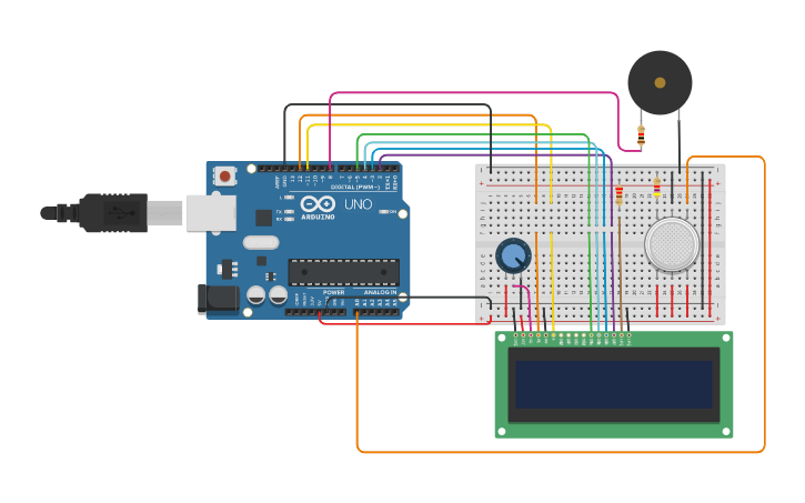
Air pollution has become a common phenomenon everywhere. Specially in the urban areas, air pollution is a real-life problem. In the urban areas, the increased number of petrol and diesel vehicles and the presence of industrial areas at the outskirts of the major cities are the main causes of air pollution. The problem is seriously intensified in the metropolitan cities. The governments all around the world are taking every measure in their capacity. Many European countries have aimed to replace petrol and diesel vehicles with the electric vehicles by 2030. Even India has aimed to do so by 2025.The main aim of this project is to develop a device which can monitor PPM in air in real time, tell the quality of air and log data to a remote server(ThingSpeak).The air monitoring device developed in this project is based on Arduino Uno. The Arduino board connects with ThingSpeak platform using ESP8266 Wi-Fi module. The sensor used for monitoring the air pollution is MQ-135 gas sensor. The sensor data is also displayed on a character LCD.
Arduino Uno is one of the most popular prototyping boards. It is small in size and packed with rich features. The board comes with built-in Arduino boot loader. It is an Atmega 328 based controller board which has 14 GPIO pins, 6 PWM pins, 6 Analog inputs and on board UART, SPI and TWI interfaces. In this IOT device, 9 pins of the board are utilized. There are six pins used to interface the character LCD. There are two pins utilized to interface the ESP8266 Wi-Fi Module and an analog input pin is used to connect the MQ-135 sensor.
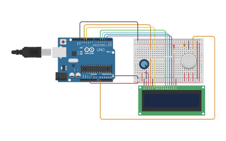
The 16X2 LCD display is used to monitor the sensor values read by the Arduino board from MQ-135. It is interfaced with the Arduino Uno by connecting its data pins D4 to D7 with pins 6 down to 3 of the controller respectively. The RS and E pins of the LCD are connected to pins 13 and 12 of the controller respectively. The RW pin of the LCD module is connected to the ground.

The ESP8266 WiFi Module is a self contained SOC with integrated TCP/IP protocol stack that can give any microcontroller access to your WiFi network. The ESP8266 is capable of either hosting an application networking functions from another application Each ESP8266 module comes pre-programmed with an AT command.The ESP8266 supports APSD for VoIP applications and Bluetooth co-existence interfaces, it contains a self-calibrated RF allowing it to work under all operating conditions, and requires no external RF parts.For connecting ESP8266 Module with Arduino Uno, you need 3.3 voltage regulator because Arduino is not capable of providing 3.3 v to ESP8266.
• 802.11 b/g/n
• Wi-Fi Direct (P2P), soft-AP
• Integrated TCP/IP protocol stack
• Integrated TR switch, balun, LNA, power amplifier and matching network
• Integrated PLLs, regulators, DCXO and power management units
• +19.5dBm output power in 802.11b mode
• Power down leakage current of <10uA
• 1MB Flash Memory
• Integrated low power 32-bit CPU could be used as application processor
• SDIO 1.1 / 2.0, SPI, UART
• STBC, 1×1 MIMO, 2×1 MIMO
• A-MPDU & A-MSDU aggregation & 0.4ms guard interval
• Wake up and transmit packets in < 2ms

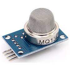
The MQ-135 gas sensor senses the gases like ammonia nitrogen, oxygen, alcohols, aromatic compounds, sulfide and smoke. The operating voltage of this gas sensor is from 2.5V to 5.0V. MQ-135 gas sensor can be implementation to detect the smoke, benzene, steam and other harmful gases.The MQ135 sensor can sense NH3, NOx, alcohol, Benzene, smoke, CO2 and some other gases, so it is a perfect gas sensor for our Air Quality Monitoring Project. When we will connect it to Arduino then it will sense the gases, and we will get the Pollution level in PPM (parts per million). MQ135 gas sensor gives the output in form of voltage levels and we need to convert it into PPM. So for converting the output in PPM, here we have used a library for MQ135 sensor, it is explained in detail in “Code Explanation” section below. Sensor was giving us a value of 90 when there was no gas near it and the safe level of air quality is 350 PPM and it should not exceed 1000 PPM. When it exceeds the limit of 1000 PPM, then it starts to cause Headaches, sleepiness and stagnant, stale, stuffy air and if it exceeds 2000 PPM then it can cause increased heart rate and many other diseases.When the value will be less than 1000 PPM, then the LCD and webpage will display “Fresh Air”. Whenever the value will increase 1000 PPM, then the buzzer will start beeping and the LCD and webpage will display “Poor Air, Open Windows”. If it will increase 2000 then the buzzer will keep beeping and the LCD and webpage will display “Danger! Move to fresh Air”.
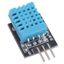
DHT11 is a part of DHTXX series of Humidity sensors. The other sensor in this series is DHT22. Both these sensors are Relative Humidity (RH) Sensor. As a result, they will measure both the humidity and temperature. Although DHT11 Humidity Sensors are cheap and slow, they are very popular among hobbyists and beginners.The DHT11 is also a basic, ultra low-cost digital temperature and humidity sensor. It uses a capacitive humidity sensor and a thermistor to measure the surrounding air and spits out a digital signal on the data pin (no analog input pins needed). It’s fairly simple to use, but requires careful timing to grab data. The only real downside of this sensor is you can only get new data from it once every 2 seconds; the sensor readings can be up to 2 seconds old.
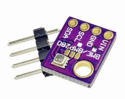
The BME280 is a humidity sensor especially developed for mobile applications and variables where size and low power consumption are key design parameters. The unit combines high linearity and high accuracy sensors and is perfectly feasible for low current consumption, long-term stability and high EMC robustness. The humidity sensor offers an extremely fast response time and therefore supports performance requirements for emerging applications such as context awareness, and high accuracy over a wide temperature range. The BME280 achieves high performance in all applications requiring humidity and pressure measurement. These emerging applications of home automation control, in-door navigation, fitness as well as GPS refinement require a high accuracy and a low TCO at the same time. The humidity sensor provides an extremely fast response time for fast context awareness applications and high overall accuracy over a wide temperature range. The pressure sensor is an absolute barometric pressure sensor with extremely high accuracy and resolution and drastically lower noise than the Bosch Sensortec BMP180. The integrated temperature sensor has been optimized for lowest noise and highest resolution. Its output is used for temperature compensation of the pressure and humidity sensors and can also be used for estimation of the ambient temperature. The sensor provides both SPI and I²C interfaces and can be supplied using 1.71 to 3.6 V for the sensor supply VDD and 1.2 to 3.6 V for the interface supply VDDIO. Measurements can be triggered by the host or performed in regular intervals. When the sensor is disabled, current consumption drops to 0.1µA
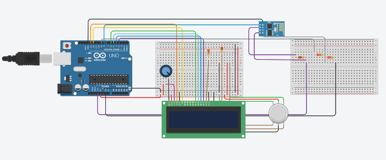
First of all we will connect the ESP8266 with the Arduino. ESP8266 runs on 3.3V and if you will give it 5V from the Arduino then it won’t work properly and it may get damaged. Connect the VCC and the CH_PD to the 3.3V pin of Arduino. The RX pin of ESP8266 works on 3.3V and it will not communicate with the Arduino when we will connect it directly to the Arduino. So, we will have to make a voltage divider for it which will convert the 5V into 3.3V. This can be done by connecting three resistors in series like we did in the circuit. Connect the TX pin of the ESP8266 to the pin 10 of the Arduino and the RX pin of the esp8266 to the pin 9 of Arduino through the resistors.
ESP8266 Wi-Fi module gives your projects access to Wi-Fi or internet. It is a very cheap device and makes your projects very powerful. It can communicate with any microcontroller and it is the most leading device in the IOT Platform Then we will connect the MQ135 sensor with the Arduino. Connect the VCC and the ground pin of the sensor to the 5V and ground of the Arduino and the Analog pin of sensor to the A0 of the Arduino. Connect a buzzer to the pin 8 of the Arduino which will start to beep when the condition becomes true.
Lastly, we will connect LCD with the Arduino. The connections of the LCD are as follows
●Connect pin 1 (VEE) to the ground.
●Connect pin 2 (VDD or VCC) to the 5V.
●Connect pin 3 (V0) to the middle pin of the 10K potentiometer and connect the other two ends of the potentiometer to the VCC and the GND.
The potentiometer is used to control the screen contrast of the LCD. Potentiometer of values other than 10K will work too.
●Connect pin 4 (RS) to the pin 12 of the Arduino.
●Connect pin 5 (Read/Write) to the ground of Arduino. This pin is not often used so we will connect it to the ground.
●Connect pin 6 (E) to the pin 11 of the Arduino. The RS and E pin are the control pins which are used to send data and characters.
●The following four pins are data pins which are used to communicate with the Arduino.
Connect pin 11 (D4) to pin 5 of Arduino.
Connect pin 12 (D5) to pin 4 of Arduino.
Connect pin 13 (D6) to pin 3 of Arduino.
Connect pin 14 (D7) to pin 2 of Arduino.
●Connect pin 15 to the VCC through the 220 ohm resistor. The resistor will be used to set the backlight brightness. Larger values will make the backlight much more darker.
●Connect pin 16 to the Ground.
As the device is powered, the Arduino board loads the required libraries, flashes some initial messages on the LCD screen and start sensing data from the MQ-135 sensor. The sensor can be calibrated so that its analog output voltage is proportional to the concentration of polluting gases in PPM. The analog voltage sensed at the pin A0 of the Arduino is converted to a digital value by using the in-built ADC channel of the Arduino. The Arduino board has 10-bit ADC channels, so the digitized value ranges from 0 to 1023. The digitized value can be assumed proportional to the concentration of gases in PPM. The read value is first displayed on LCD screen and passed to the ESP8266 module wrapped in proper string through virtual serial function. The Wi-Fi module is configured to connect with the ThingSpeak IOT platform. ThingSpeak is an IOT analytics platform service that allows to aggregate, visualize and analyze live data streams in the cloud. ThingSpeak provides instant visualizations of data posted by the IOT devices to ThingSpeak server.
The Wi-Fi module can be connected with the ThingSpeak server by sending AT commands from the module. The module first test the AT startup by sending the AT command. Then, command is passed by the controller to the Wi-Fi module using software serial function. In response to the command 'AT', the platform must respond with 'OK' if the cloud service is running.
Then, the AT command to view the version information is passed. AT + GMR In response to this command, the IOT platform must respond by sending back the version information, SDK version and the time bin is compiled. 1. ESP-01 output : it will be 00160901. 2. ESP-12 output : it will be 00180000902-AI03. Next, the AT command to set the connection to Wi-Fi mode is send. AT + CWMODE = 3
By setting the parameter in CWMODE to 3, the Wi-Fi connection is configured to SoftAP as well as station mode. This AT command can take three parameters 1 - set Wi-Fi connection to station mode 2 - set Wi-Fi connection to SoftAP mode 3 - set Wi-Fi connection to SoftAP + station mode In response to this command, the IOT platform must send back the string indication the Wi-Fi connection mode set.
Next, the AT command to reset the module is send. AT + RST In response to this command, the Wi-Fi module must restart and send back a response of 'OK'. After resetting the module. Next, command to setup multiple connections is AT+ CIPMUX. AT + CIPMUX=1 This AT command can take two parameters - 0 for setting single connection and 1 for setting multiple connections. Next, the command to connect with the Access Point (AP) is passed which takes two parameters where first parameter is the SSID and the other parameter is the password. AT+CWJAP=\"SSID\",\"Password\" Next, the AT command to get local IP address is passed. AT + CIFSR
In response to this command, the local IP address of the Wi-Fi connection is sent back by the module. Now, the module is ready to establish TCP IP connection with the ThingSpeak server. The controller reads the sensor data and store it in a string variable. The TCP IP connection is established by sending the following AT command AT + CIPSTART = 4, "TCP", "184.106.153.149", 80
The AT + CIPSTART command can be used to establish a TCP connection, register an UDP port or establish an SSL connection. Above command is used to establish a TCP IP connection. For establishing a TCP-IP connection, the command takes four parameters where first parameter is link ID which can be a number between 0 to 4, second parameter is connection type which can be TCP or UDP, third parameter is remote IP address or IP address of the cloud service to connect with and last parameter is detection time interval for checking if the connection is live. If the last parameter is set to 0, the TCP keep-alive feature is disabled otherwise a time interval in seconds range from 1 to 7200 can be passed as parameter. In response to this command, the server must respond with 'OK' if connection is successfully established otherwise it should respond with message 'ERROR'. When the connection with the server is successfully established and the controller has read the sensor value, it can send the data to the cloud usingAT+CIPSEND command. AT + CIPSEND = 4
This command takes four parameters, where first parameter is the link ID which can be a number between 0 to 4, second parameter is data length which can be maximum 2048 bytes long, third parameter is remote IP in case of an UDP connection and remote port number in case of UDP connection. The third and fourth parameters are optional and used only in case of UDP connection with the server. Since, the TCP IP connection is established, these parameters are not used. The command is followed by a string containing the URL having the field names and values passed through the HTTP GET method.
In this project, a string containing the API Key and the sensor value as the field and value is passed. The passed field and its value are logged on the cloud server. It is important to pass the API key in this as one of the field value in order to connect with the registered cloud service. The Air quality measured by sensor can now be monitored and recorded through the ThingSpeak IOT platform.