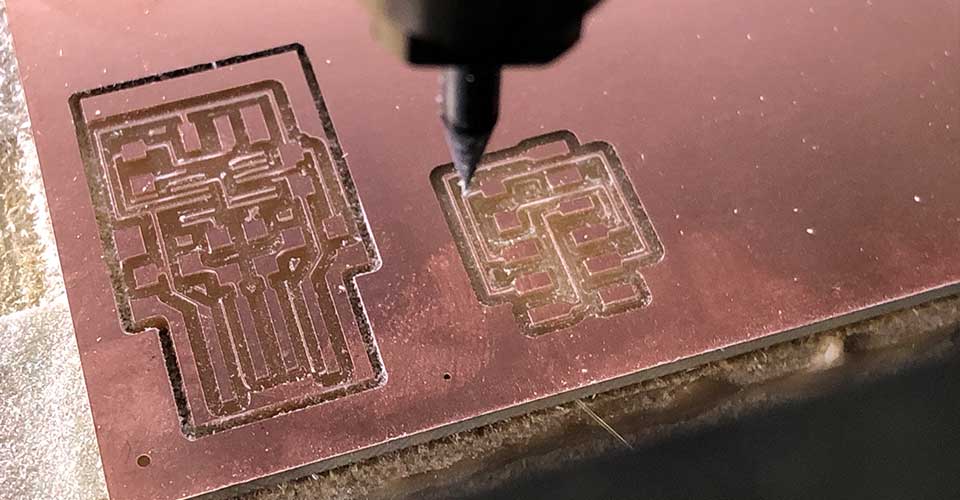
Electronics Production
ELECTRONIC PRODUCTION
This is the content we had covered this week:
W4 - Elecronics production
- Electronics basics
- What is a microcontroller
- Understanding the boards and getting started
Assignment
-
Group assignment: Characterize the design rules for your PCB production process
-
Individual assignment: make an in-circuit programmer by milling and stuffing the PCB,test it, then optionally try other PCB processes
This week we’ve been working to create different PCBs by PCB milling. We covered some principles on electricity and microcontrollers.
HOW TO MAKE A PCB
HOW ELECTRICITY WORKS
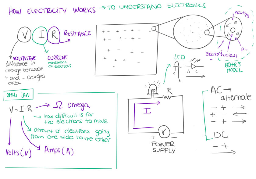
"Diagram showing how electricity works before learning electronics."
We had a session where we learned some Arduino basics while understanding some electricity principles.
TRAINING | ARDUINO
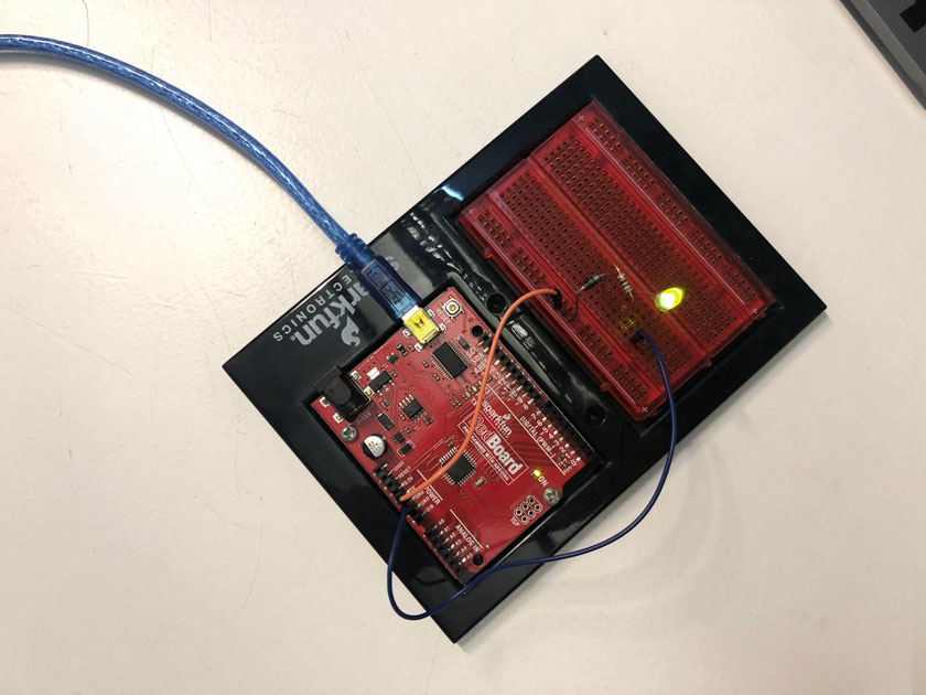
"Arduino board with a protoboard connected to a Led, a resistor and a capacitor."
There was a lot of theoretical content this week. The following illustrations try to summarize the core concepts.
WHAT ARE MICROCONTROLLERS?
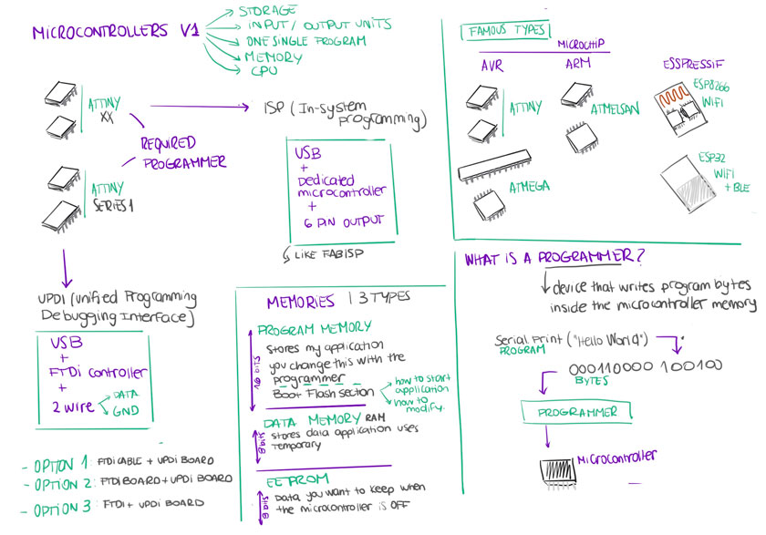
"Diagram showing what microcontrollers are.
HOW TO CREATE A PCB
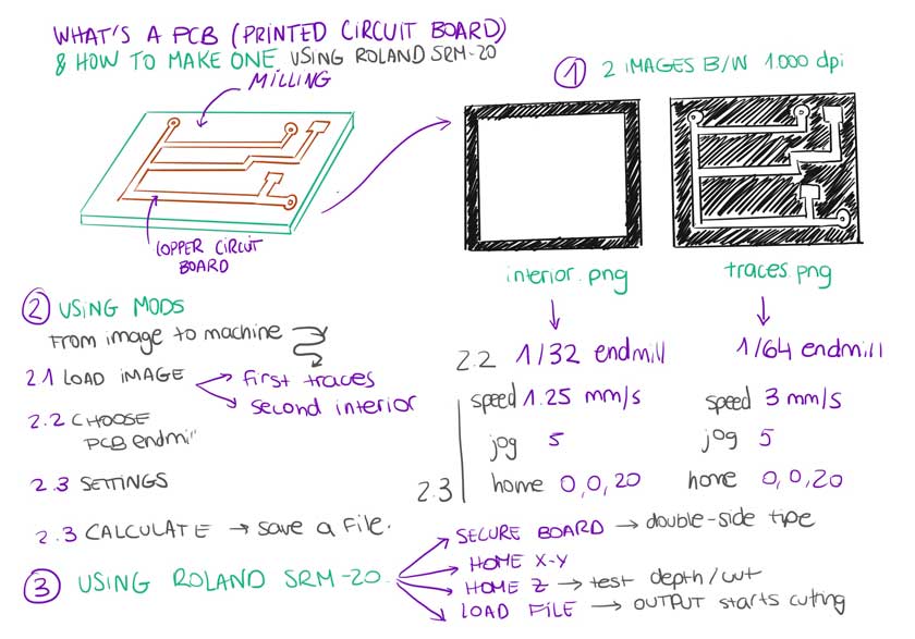
"Diagram showing how the create a PCB"
HOW TO SOLDER PCBs
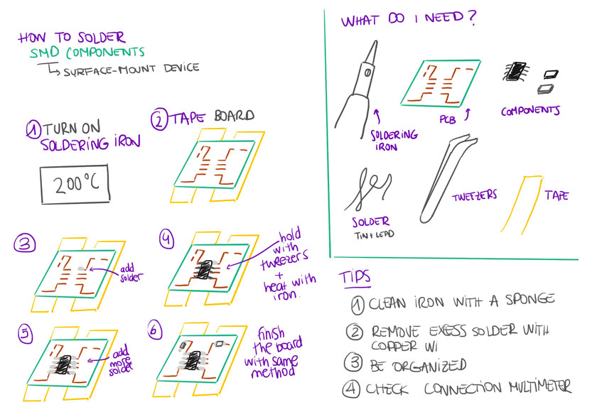
"Diagram showing how the solder PCBs"
TRAINING | SOLDERING SMD COMPONENTS
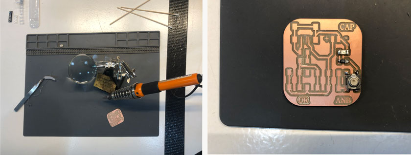
"Testing SMD components soldering on a sample PCB. "
GROUP ASSIGNMENT
The group’s assignment focus was on understanding the workflow and the nuances of the different PCB milling tools.
Here a series of screenshots that showcase a setup we tried to define the best settings for the Roland Roland SRM-20. In this case is the whole process for the conventional method.
SETTING UP MODS PROJECT

"Mods: Landing Page"

"Mods: Open Project"
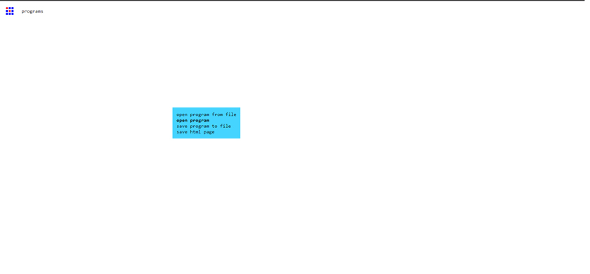
"Mods: Open program"
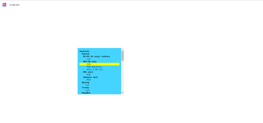
"Mods: Select Machine"
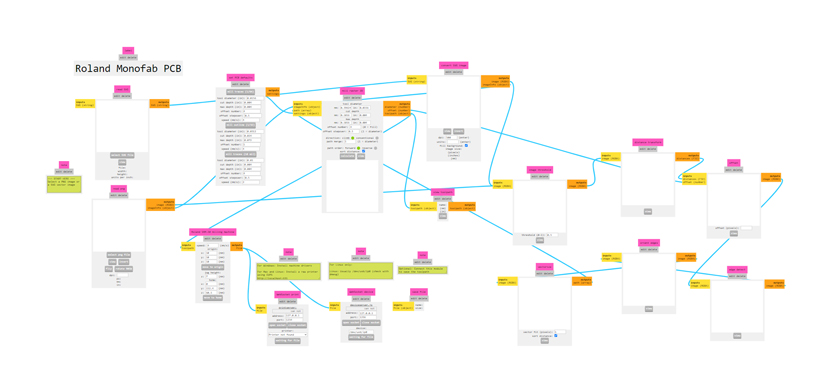
"Mods: pipeline for Roland SMR-20"
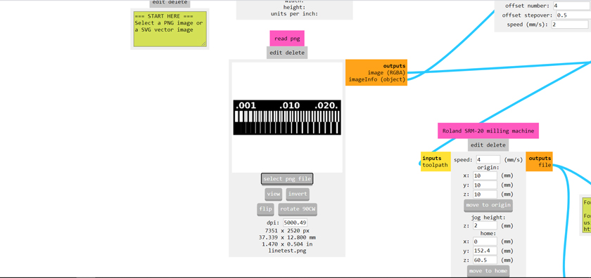
"Mods: Load file"
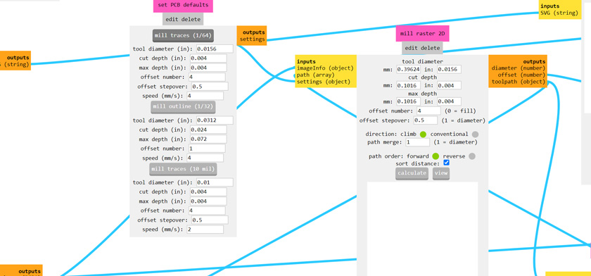
"Mods: Choose 1/64 Endmill to cut the traces. "
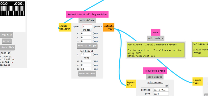
"Mods: Set speed to 3 mm/s "
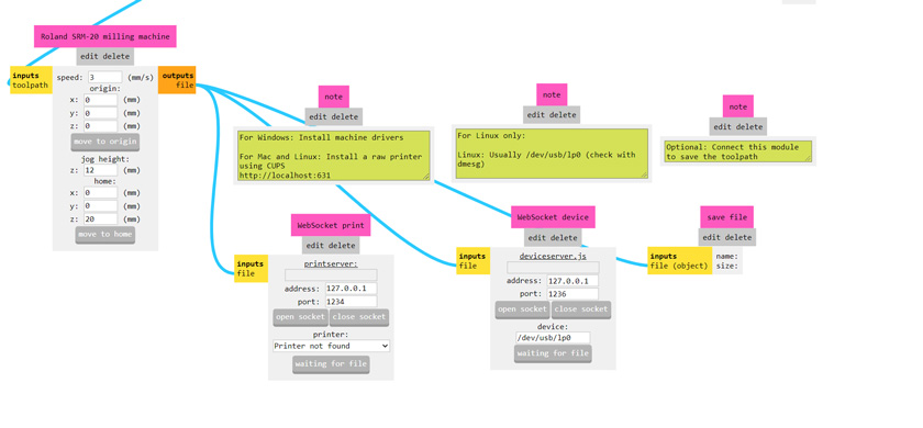
"Mods: Set save file"
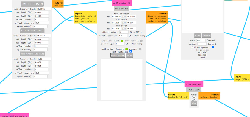
"Mods: Calculate --> Calculating"
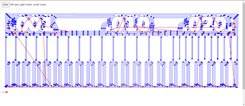
"Mods: File preview."
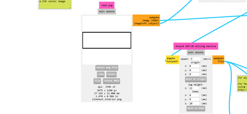
"Mods: Load Interior file"
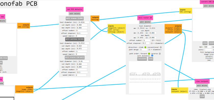
"Mods: Load 1/32 settings "

"Mods: Change speed"
FIRST TEST
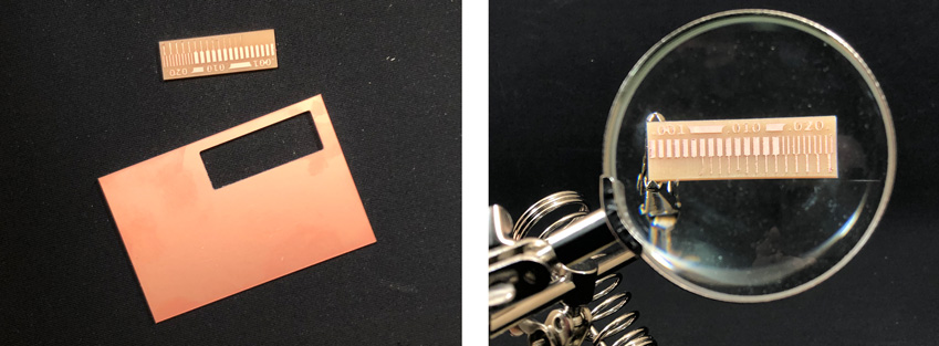
"Image of the tolerance test done with Roland SRM-20"
GROUP SETTINGS
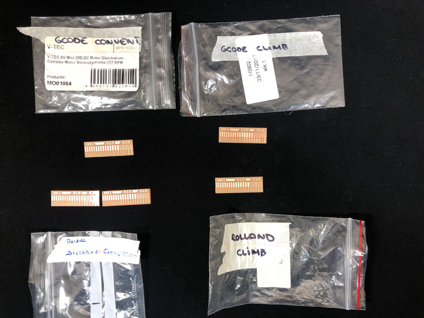
"Image showing the 4 test done: Roland SRM-20 both convencional & Climb, G-Code both Convencional & climb."
Download Roland File for traces; Download Roland File for interior
Download G-Code file for traces; Download G-Code file for interior
WHAT WENT WELL
Quick workflow: The Roland has an easy workflow.
Conventional settings worked better for finer details. Climb settings had less tolerance.WHAT COULD BE BETTER
G-Code Milling Machine: The workflow requires more attention, as the interface and homing processes are less user friendly. However, it’s a great and affordable tool.
WEEKLY ASSIGNMENT | PCB
This week’s assignment required the production of two PCBs:
FTDI SERIAL (hello.USB-serial.FT230X) + adapter UPDI (hello.serial-UPDI.FT230X)
I appreciated having the group assignment before, so it gave me a better idea of the steps to follow when I had to go on my own.
STEP 1: CREATING FILES TO MILL
Using two images for each board (one for the traces and the other to cut the board):
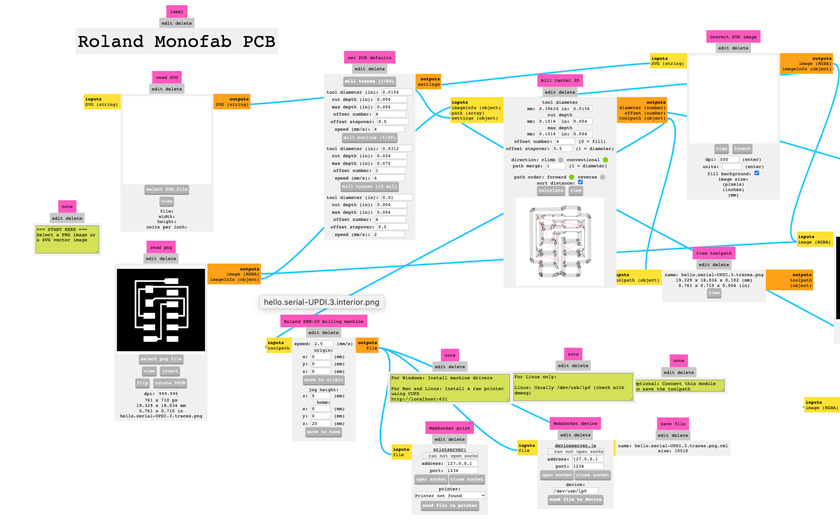
"Using Mods project to create the files for the Roland milling Machine. From .png to. rml."
STEP 2: MILLING TRACES
For both PCBs the process was the same: Milling traces first and milling interior afterwards. The trace uses 1/64 endmill and needs to be perfectly set to remove the right amount of material. My settings were 2.5 mm/s, 5 mm for jog and a depth of 1.75 for the material.
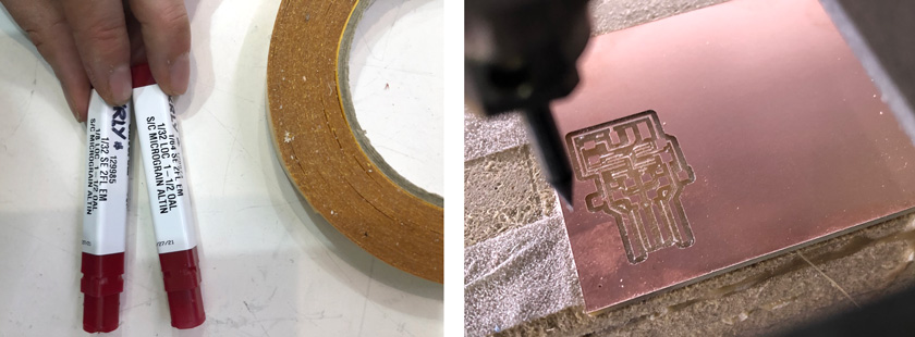
"LEFT: 1/64 + 1/32 Endmills. RIGHT: First PCB Milling process."
As you can see, my first board didn’t turn out as expected. The outline was set to 4 instead of 3 and it removed too much material. As a result the traces for the MC were extremely thin.
"Milling second PCB in action with new settings."
STEP 3: MILLING INTERIOR
Milling interior to make the cut out of the PCB is done using the 1/32 endmill and a different set of settings for both speed and depth of cut. In this case 1.25 mm/s and 5 mm jog.
"Cutting out the PCB by milling. "
As you can see here, there is a PCB that got damaged. Unfortunately, the material detached from the board, and the endmill took an expected spin. To ensure that the PCB would work I decided to repeat the milling process until I got it right on the second attempt.
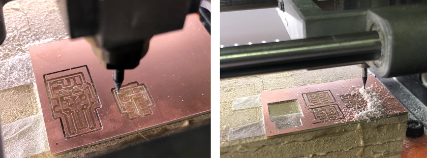
"LEFT: Milling second board. RIGHT: Milling second board again after first got damaged by the end mill."
Download Roland File USB- UPDI for traces; Download Roland File USB-UPDI for interior
Download Roland File Serial- UPDI for traces; Download Roland File Serial- UPDI for interior
STEP 4: SOLDERING COMPONENTS
Looking for the components was another challenge of the week. It was tricky to find the components as usually the number on the component doesn’t match the technical description. My advice is to look always for the kind of component that you need and the value. As you can see in this screenshot I decided to have both, to be able to double check the values.
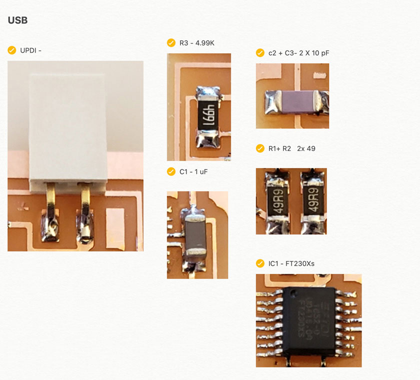
"Image showing SMD components list."
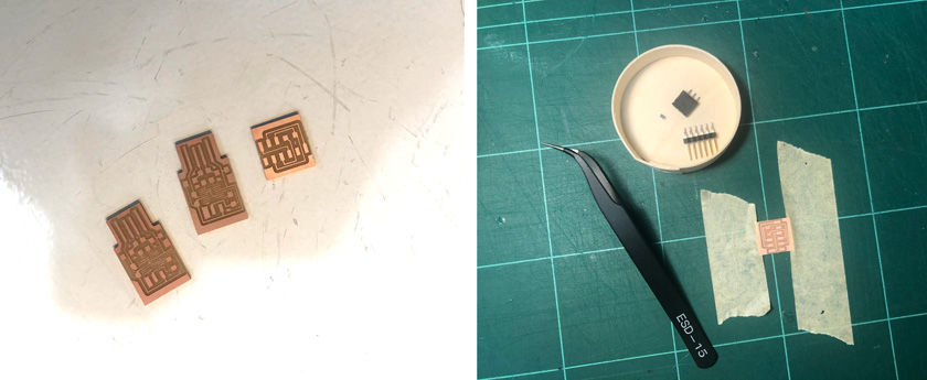
"LEFT: PCBs ready to add components. RIGHT: Soldering setup. "
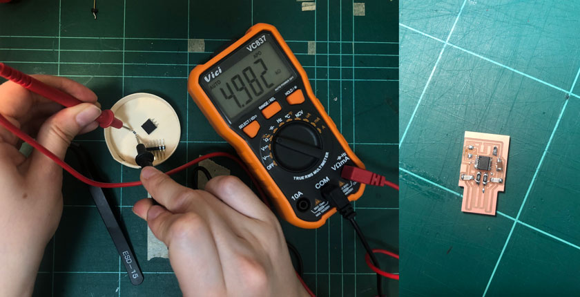
"LEFT: Checking components' values with the multimeter. RIGHT: Damaged board after desoldering a component that didn't work properly ."
To be honest, I was very bummed that I had to start again because I damaged one of the traces when removing a resistor that stopped working ( I still don’t know why). I decided to keep soldering the rest of the components to practice soldering such tiny elements.
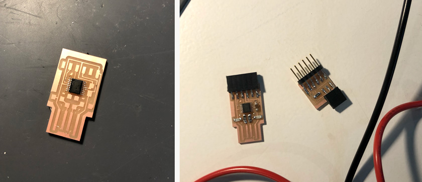
" LEFT: Microcontroller soldered. RIGHT: All components soldered."
I tried to solder the newly milled PCB with so much care! It took me forever to solder the microcontroller, but in the end, it paid off.
STEP 5: TESTING & IT WORKS!!
The first time I tried to connect my FTDI, I checked carefully that there were no The first time I tried to connect my FTDI, I checked carefully that there were no loose traces. I scratched the end of the USB connector to remove all the copper to prevent any short.
I plugged in my MacBook, and nothing happened. I realized that the USB connector was way thicker than my FTDI, and I added a piece of plastic behind it to add some width.
The second time I tried, I used one of the class’ Windows computers that one of my peers had already tried successfully. AND IT WOOOOOOOORKED! I felt extremely happy ( and relieved).
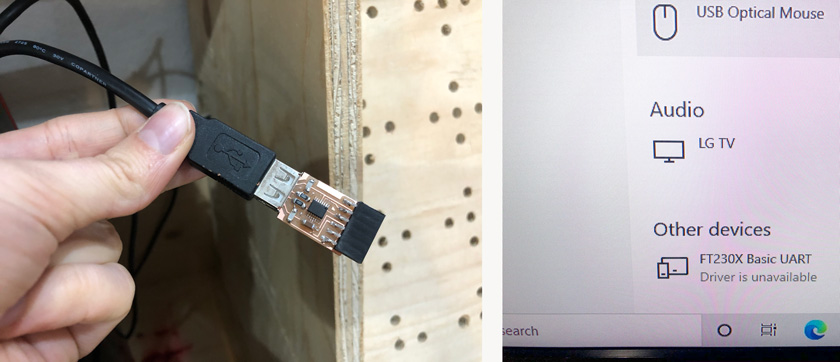
"LEFT: FT230X connected to a windows computer. RIGHT: Windows screenshot showing FT230X being detected."
Finally, I decided to try again to plug it into my computer. And this time worked! YAY!
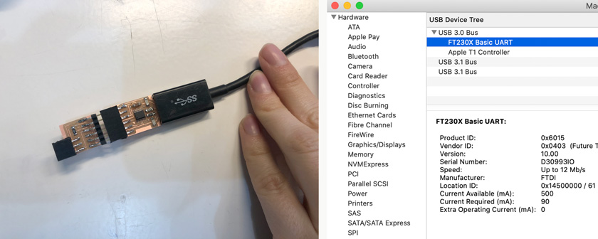
"LEFT: FT230X connected to a mac computer. RIGHT: Mac screenshot showing FT230X being detected."
FINAL SHOT
This is the final shot I took of my boards.
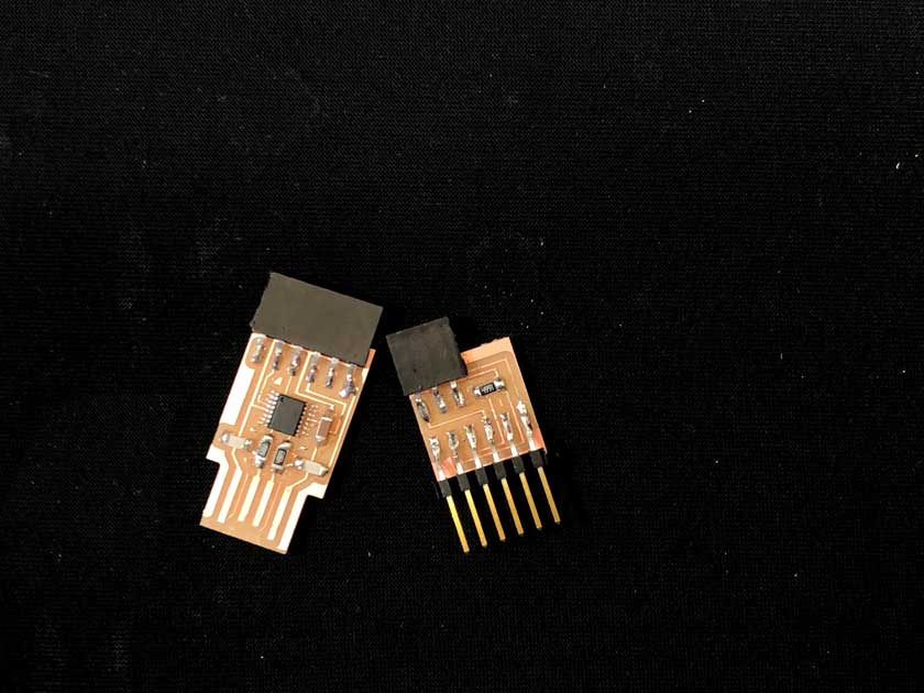
"FTDI SERIAL (hello.USB-serial.FT230X) + adapter UPDI (hello.serial-UPDI.FT230X)"
WHAT WENT WELL
It worked! I enjoyed working with the Roland SMR-20
The PCB fabricationprocess ended up being clear for me.WHAT COULD BE BETTER
Improve settings: Some traces were too thin and delicate in comparison to the design.
Soldering the microcontroller: It was very tricky, it requires more practice.
More understanding: I’d have liked to know better the funcionality of what we were doing.
