
Applications & Implications
APPLICATIONS AND IMPLICATIONS
This is the content we had covered this week:
W16 - Applications and implications
This week was quite stressful, there were so many parallel things to accomplish to try to meet the deadline. Here I’ll present the project’s schedule and later I’ll show what I’ve accomplished this week along with answering the project’s questions.
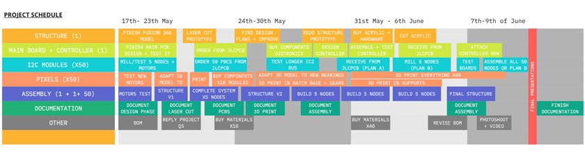
"Gantt chart showing all the taks I need to do separate in different categories according to the project's main parts."
And now, I just need to do it!
FINAL QUESTIONS FOR MY FINAL PROJECT
Document a final project masterpiece that integrates the range of units covered, answering:
WHAT DOES IT DO?
My final project is a phygital display that allows users to encode physical pixels using the genetic code: A,T,C,G creating a volumetric interactive experience that conveys some of the complexities that the DNA entitles.
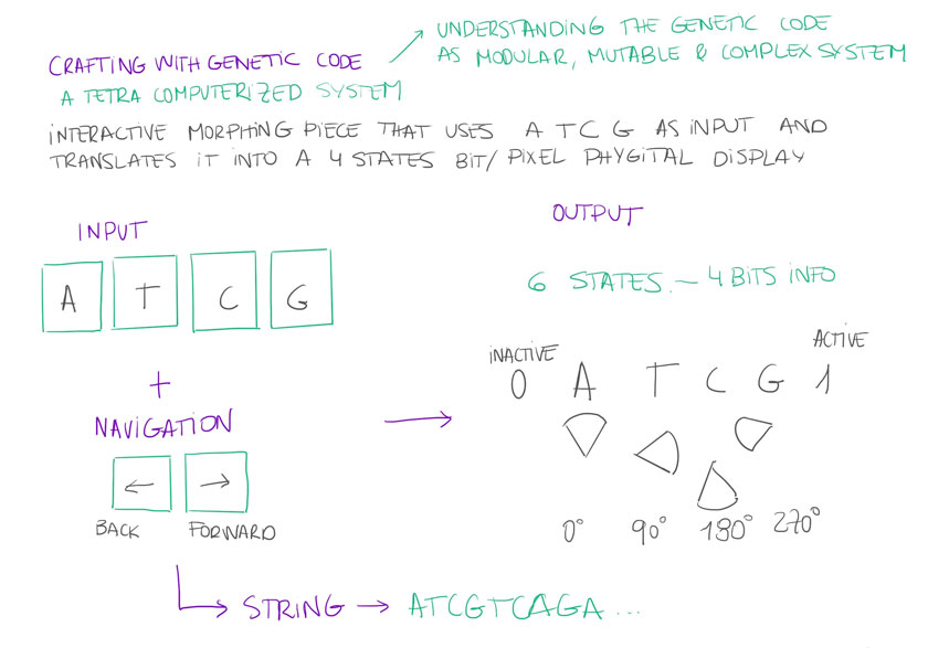
"Visual explanation of the rationale behind my final project."
The main idea is to take advantatge of some logics of Computation & Digital Fabrication in order to convey the different states that the genetic code can have and how those changes relate to the whole of such a large system.
To sum up a bit, the object is meant to have a significant size and be positioned from the waist to eye-line height.
The kinetic piece will have 3 main components: The body, the interface and the display.
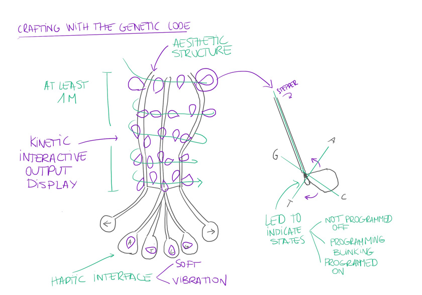
" First sketch of the Final Project Object."
As explained above, the input and interface will be the for letters of the genetic code A, T, C, G. The user will have the agency to “Type” the genetic code and to have a phygital display that will encode the genetic code in a pattern that it will be both intelligible but expressive and furthermore, alive. There’re additional controls to move along the letters and change the value as if you were on a text processor typing.
Each one of the elements of the display will have 4 positions according to each one of the 4 letters. The form and its functioning will be further developed in the next stage of the project.
WHO’S DONE THAT BEFOREHAND?
I haven’t found any physical project using the genetic code as programming language. However there are many wonderful projects that serve as a reference to develop this project. See References section.
As for Fabacademy projects that I could find that I could somehow relate, find a list here.
See physical Display fab project
See Soft Interface fab project
See Mechanism Design fab project
See Multiple mechanical outputs fab project
WHAT DID YOU DESIGN
Acrylic structure WIP. STATUS: Cardboard prototype.
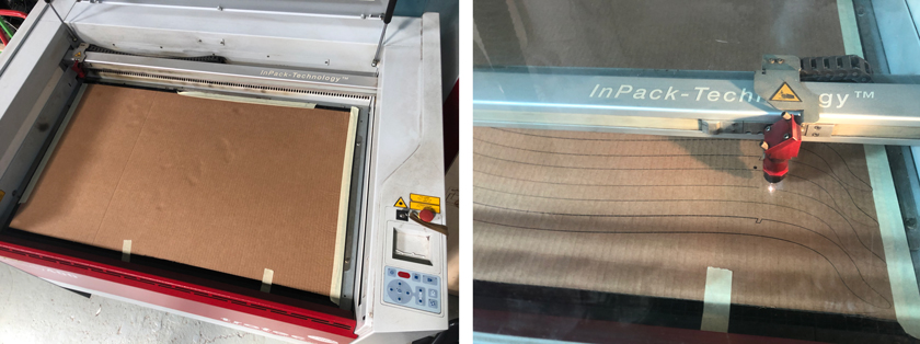
"LEFT: Trotec 400 ready for cutting. RIGHT: Laser cutting structure framing."
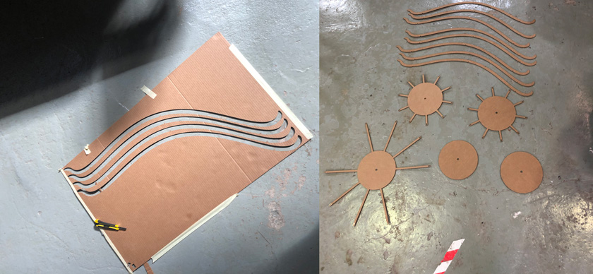
"LEFT: Cardboard cutout. RIGHT: All structure pieces ready to assemble."
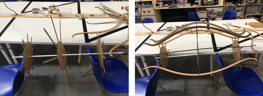
"LEFT: "Fancy" Setup to put together the structure. RIGHT: Adding pieces one by one while realising some design flaws. "
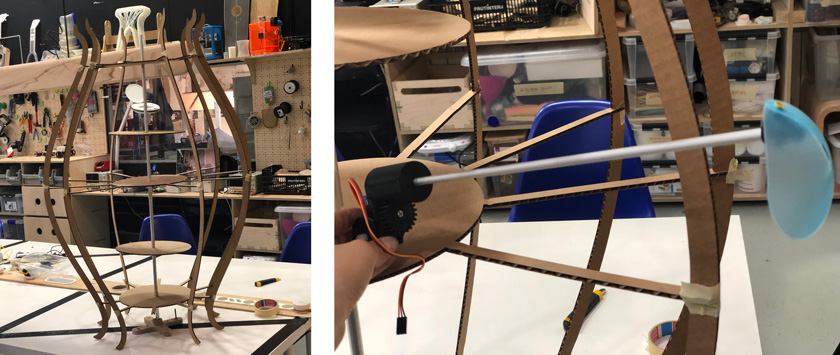
"LEFT: Tadaaaah, structure v1. RIGHT: Pixel in place. "
After assembling it, it felt like I needed a proper support for the base.
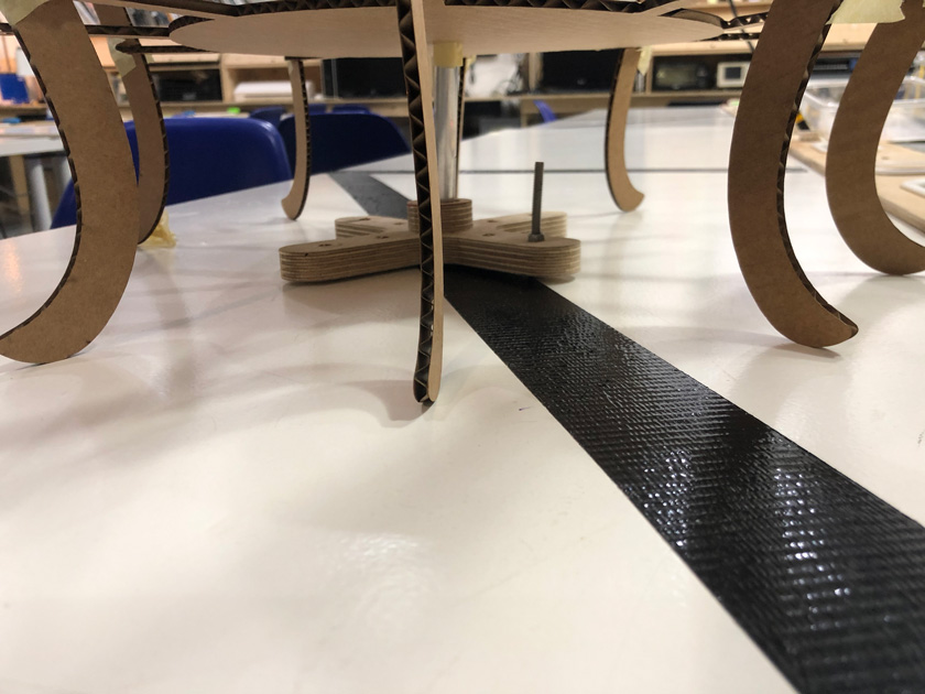
"To hold the structure in place I added a wooden piece I found around the lab. I'm considering adding it to the design."
Gear Box ALMOST DONE
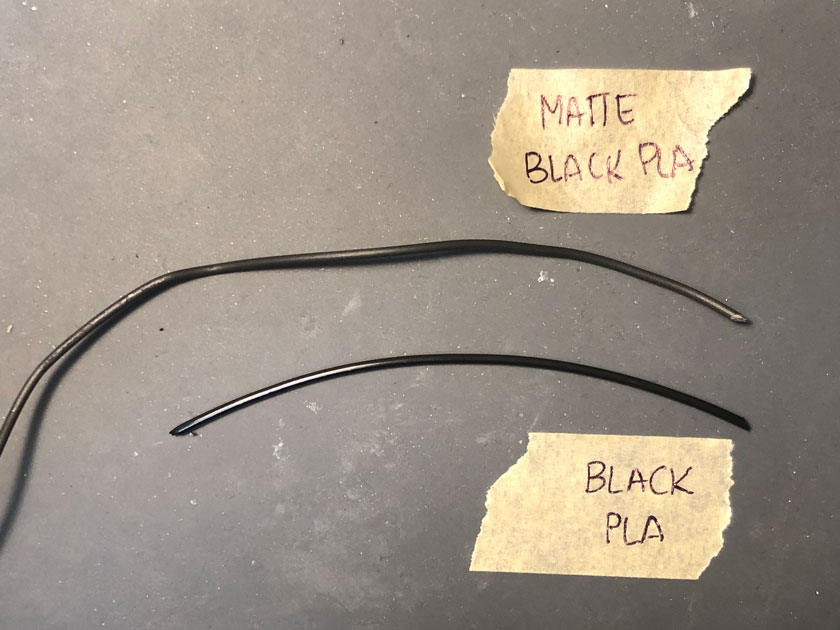
"New filament for the gear box & pixel elements, black matte. "
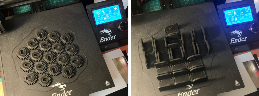
"LEFT: Gears with new insert. RIGHT: Printing bases to test on the structure. "
"Adding insert with the soldering iron tip."
Mobile Physical Pixels KINDA DONE
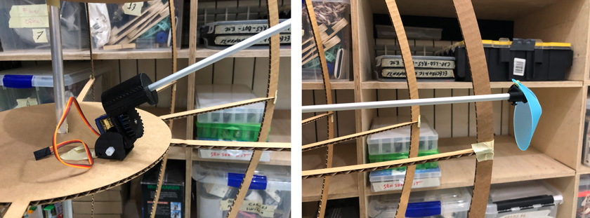
"LEFT: gear box in place. RIGHT: Pixel in place."
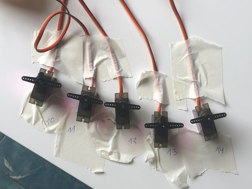
"5 servos attached to the i2c nodes with the i2C addresses written on tape."
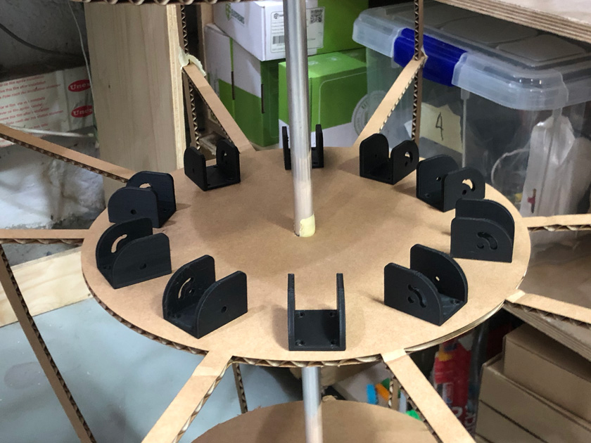
"3d printed bases tryout on the structure."
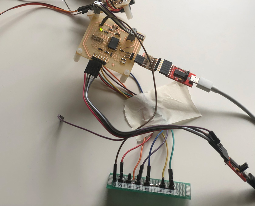
Main board DONE
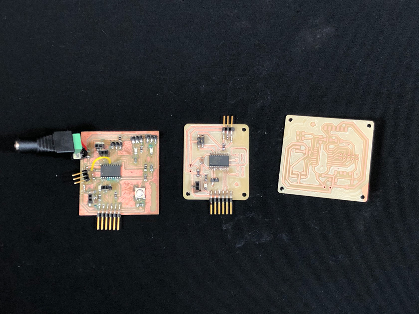
"3 iterations of the main board."
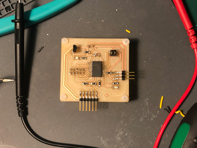
"Last version for the Main board for my final project."
Secondary boards (to control the Physical pixels using I2C) DONE
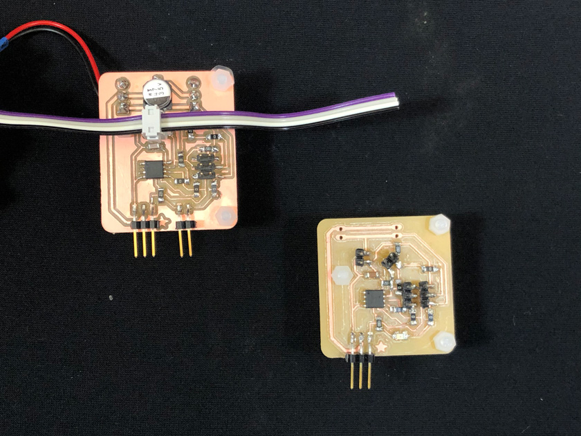
"2 iterations of the secondary board."
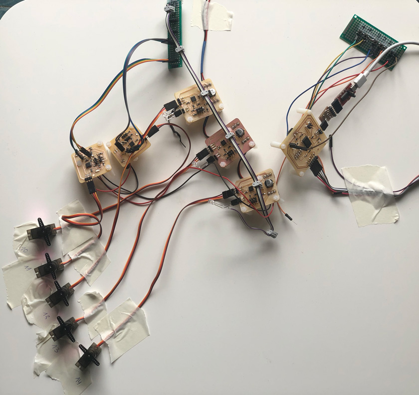
"5 I2C secondary boards connected to the main board and controlling 5 servos."
"Pressing A,T,C,G to move servos and changing module using arrows (led changing state)."
Interface - (not anymore soft) WIP
"Close-up of the prototype for the inputs interface."
WHAT MATERIALS AND COMPONENTS DID YOU USE? WHERE DID THEY COME FROM? AND HOW MUCH DID THEY COST?
Still WIP. I’ll be updating the list as some hardware has been updated and I expect some minor changes on some consumables such as screws, nuts, spacers & bolts.
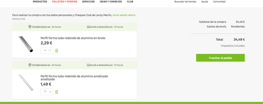
STRUCTURE: 2x 12 mm aluminium rod. 2x threaded rod. 10x nuts. 2x 1000mm x600 mm fluor blue edge acrylic. 2x 1000mm x600 mm smoked acrylic.
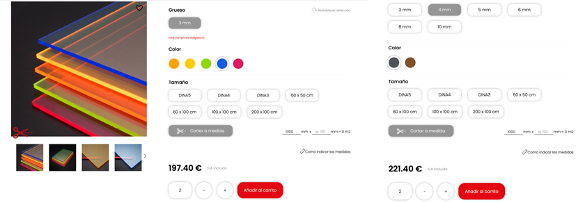
"LEFT: acrylic quote for outer part of the structure. RIGHT: Acrylic quote for inner part of the structure"
PIXELS: 50 x 30mm long, 6mm diameter anodized aluminium rod. 50x servo motors. 50x 3D printed gears. 50X 3D printed structures. 50x bearings 6mm diameter. 50x bearings 5mm diameter. 50x 3D printed base. 3 X 50 hegaxonal spacers + nuts.
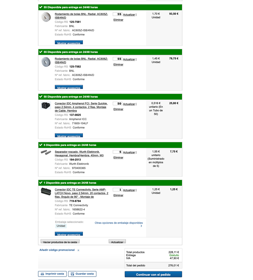
"RS bill for bearings + IDC connectors "
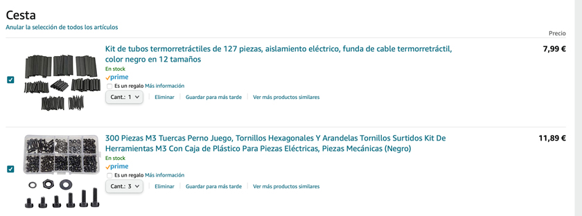
"Black heat-shrink tubing + bolts, washers & nuts."
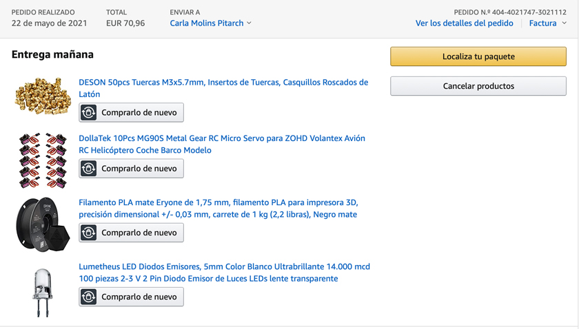
"Inserts, servo motors ( metal shaft), black matte filament + ultra bright LEDs."
PCBs: 1 main board. 50 secondary boards.
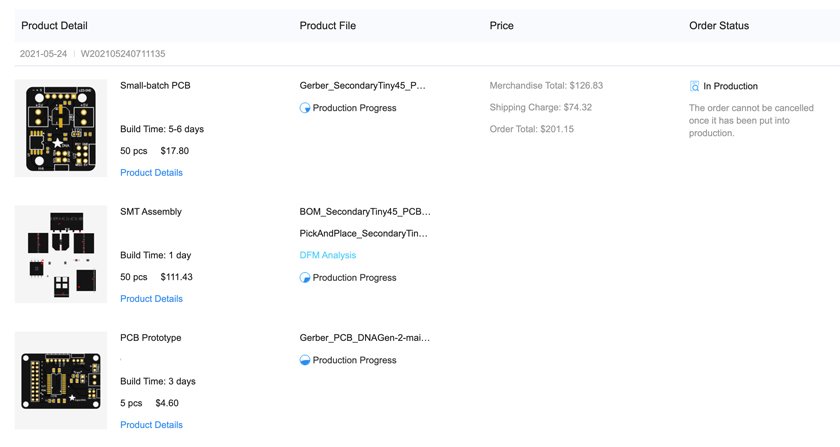
"JLCpcb production panel."
PHYSICAL INTERFACE:
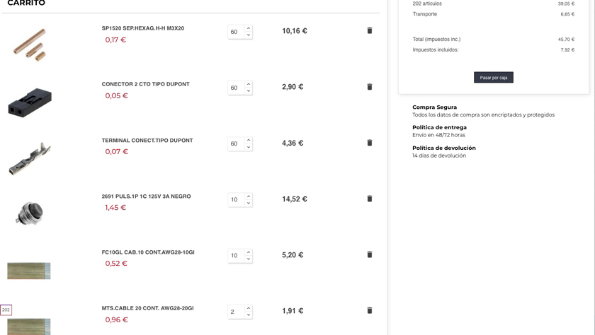
"Diotronic quote for switches, dupont connectors & wire."
POWER: Power supply + clear cable.
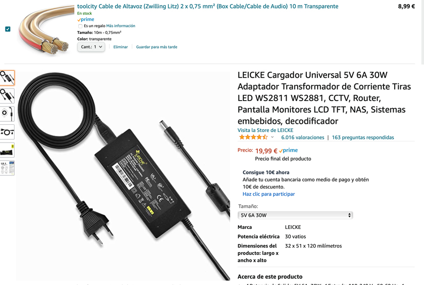
"Wire for power + power supply."
""
Up to this moment, this is the approximate bill of materials:
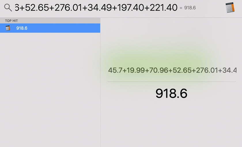
""
I expect at least almost 100€ more in motors as I only got 10 and some more hardware.My expected BOM I’d be around 1200€
WHAT PARTS & SYSTEMS WERE MADE?
Structure: Laser cut. Base joints: 3d printer Interface: Laser Cut + Vinyl Cutter Gear Box (including: base, Motor support, Geared shaft, Servo Gear, Spacers and rod topper): 3d printer Pixel: Laser Cut Pcbs: prototype milling machine | Final serial fabrication.
WHAT PROCESSES WERE USED?
- CAD, 3D PRINTING, LASER CUT, ELECTRONICS DESIGN, ELECTRONICS PRODUCTION.
WHAT QUESTIONS WERE ANSWERED?
When I started designing this project I wasn’t sure if a system that included so many nodes was feasible. Even though originally I wanted to have 96 I2C nodes, I settled on having 50 and they work which is great.
I also wondered how stable the system was going to be given that the I2C bus was so long. I’d say it’s functional but sometimes it gets stuck. I’ll keep working on reducing the nouse.
WHAT WORKED? AND WHAT DIDN’T?
For now I’ve 5 modules working. Plan A is having 50, plan B would be having 10.
In the end I ended up having 49 out of 50 functional nodes. The system is fully functional even though the interface is a bit flickery, some buttons don’t always work. I plan on replacing the interace in the future.
HOW WAS IT EVALUATED?
My main goal was to be able to control 50 nodes independently, and that was achieved.
The user experience was essential, and it needs another iteration to allow independent interaction. As for now, it needs some supervision as some wires might get tangled.
WHAT ARE THE IMPLICATIONS?
This project brings agency to users to explore complex genetics playfully and entertainingly. This accessibility towards a theme that would be restricted to scientific audiences democratizes knowledge and allows people to talk and wonder about these topics.
Some of these questions are updated on the Project and Develepment page: