Assignment
- Group Assignment:
- characterize the design rules for your PCB production process
- Individual Assignment:
- make an in-circuit programmer by milling and stuffing the PCB, test it, then optionally try other PCB processes
Group Assignment
- Group Members: Daniel Wilenius, Dann Mensah, 吳若玄 (Russian Wu)
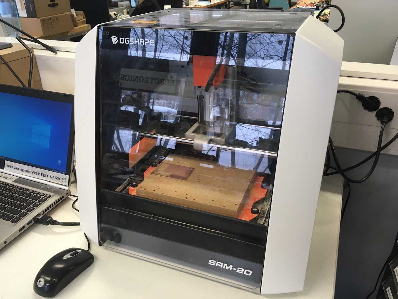
Milling Machine - SRM-20
Equipments we need:
-
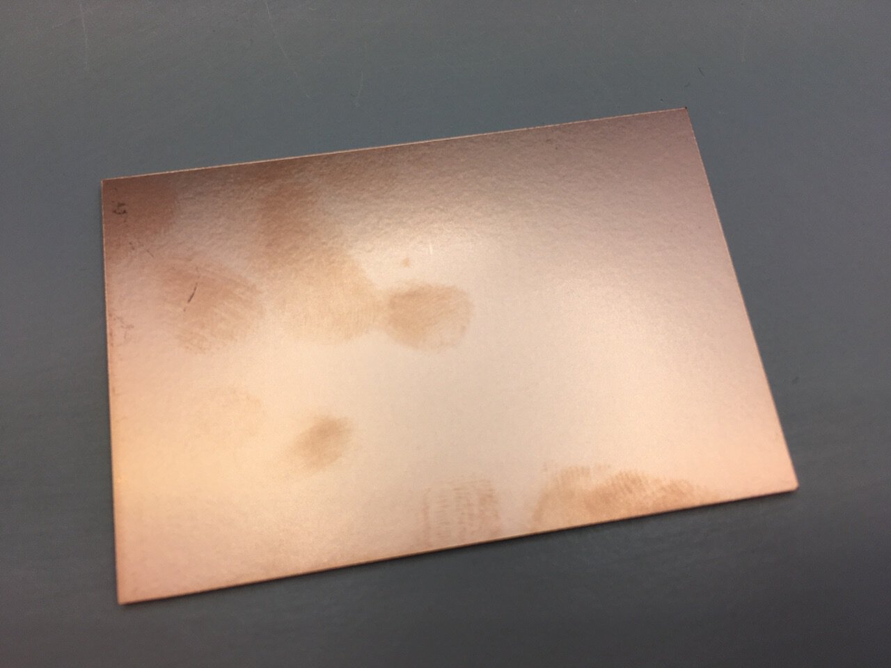
one-sided Copper board
-
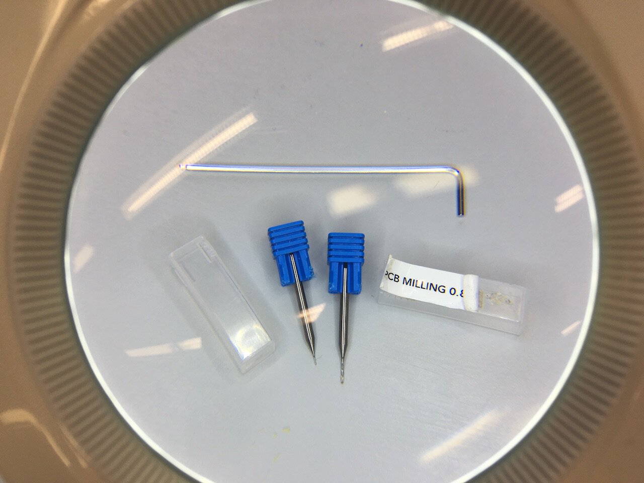
0.3, 0.4mm, and 0.8mm milling bits
-
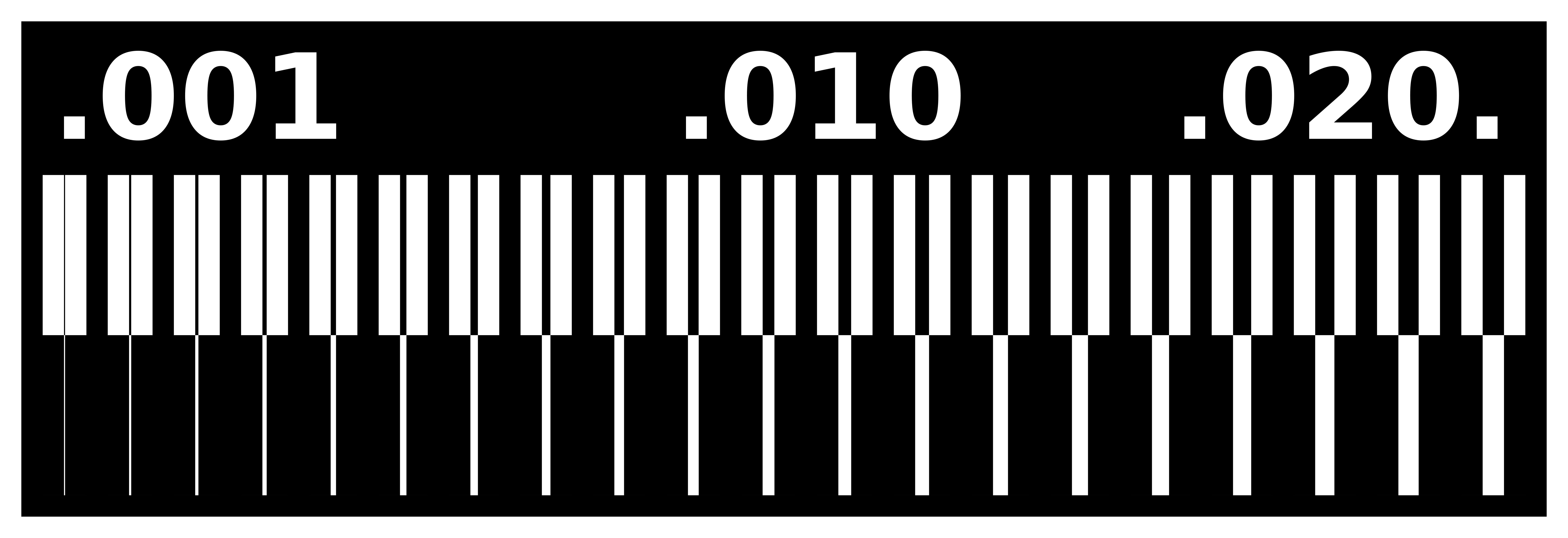
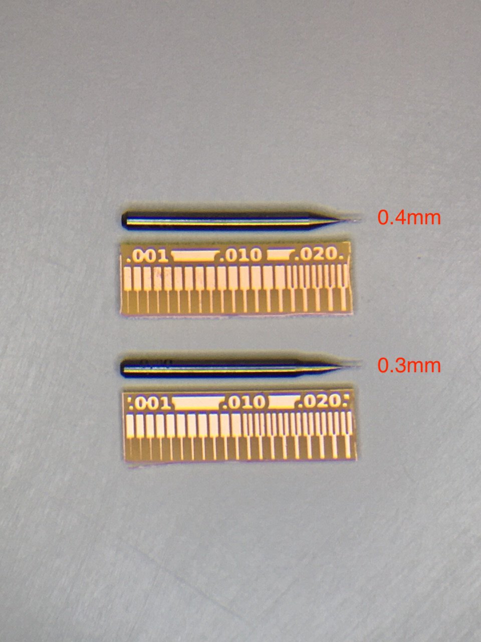
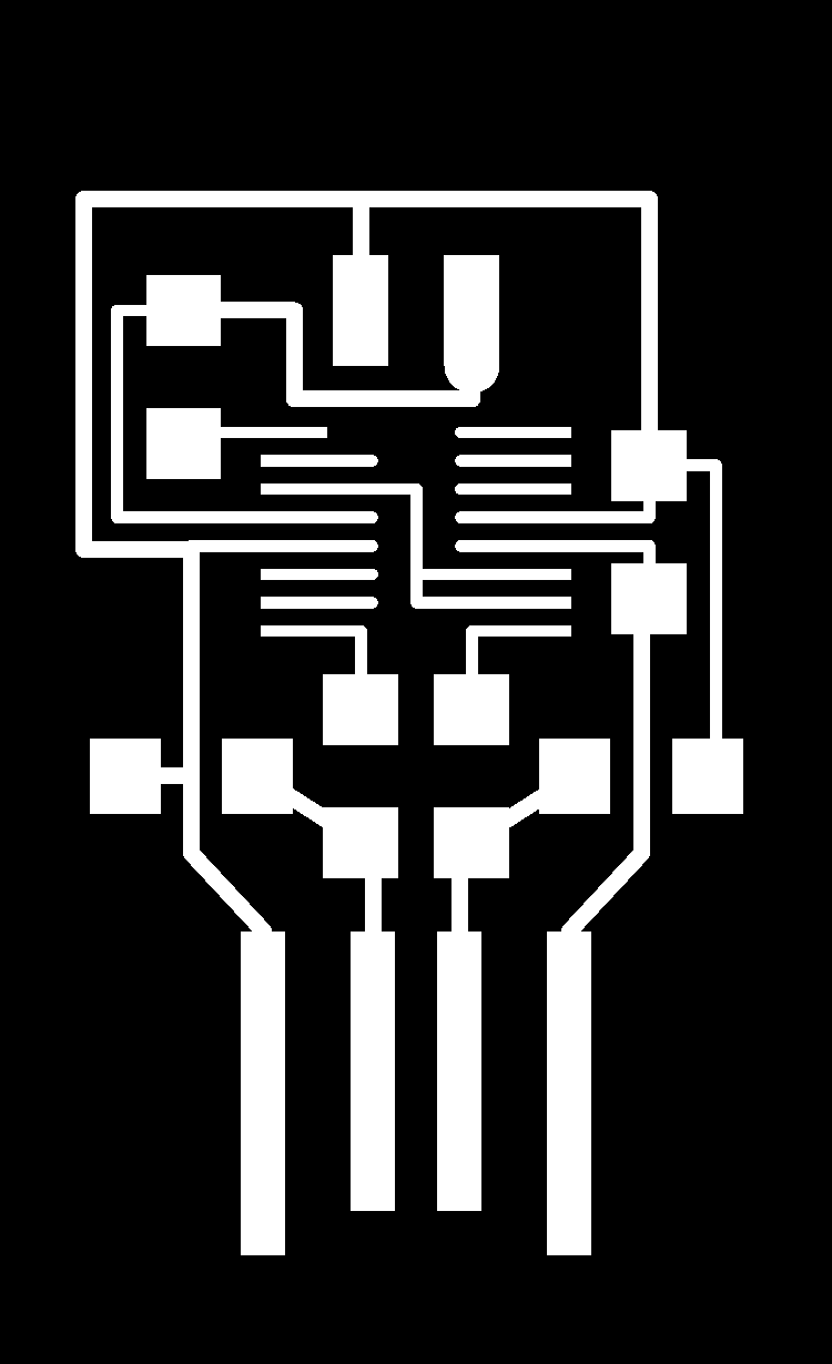
Line test pictures, the white parts are going to be kept.

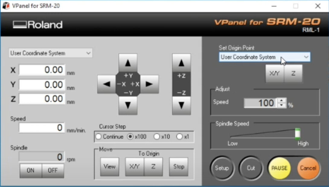
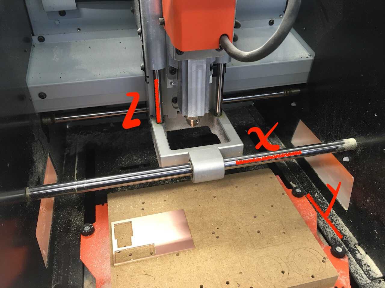
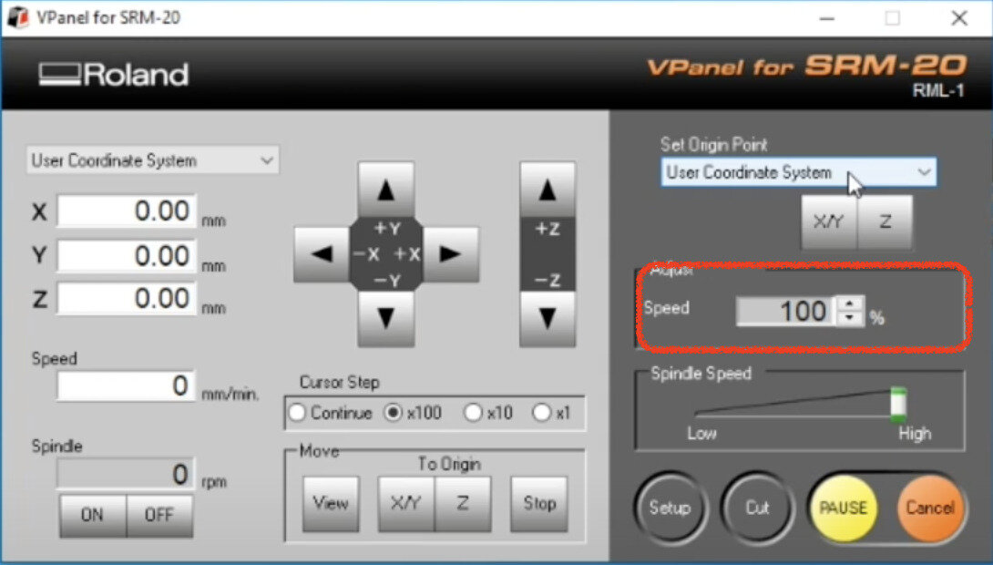
Milling Machine (SRM-20) setting up
Set the origin of the z-axis first and then the x/y-axis.
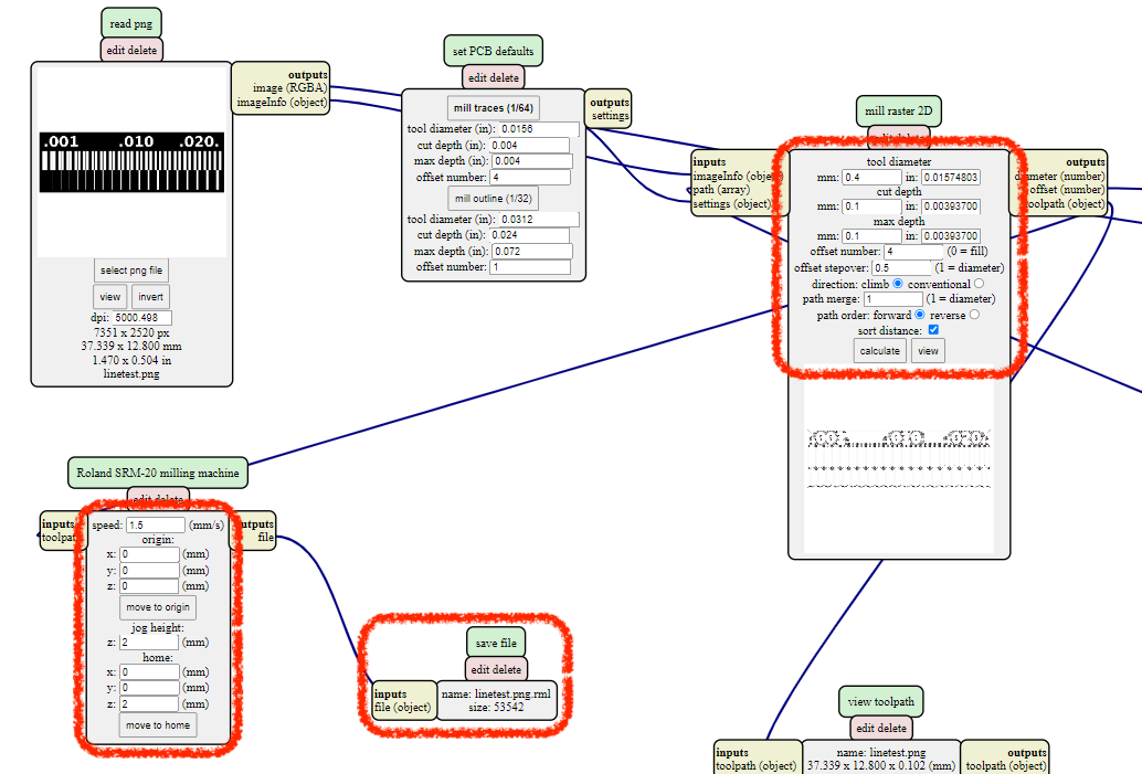
Create the milling path for PCB (Printed Copper Board)
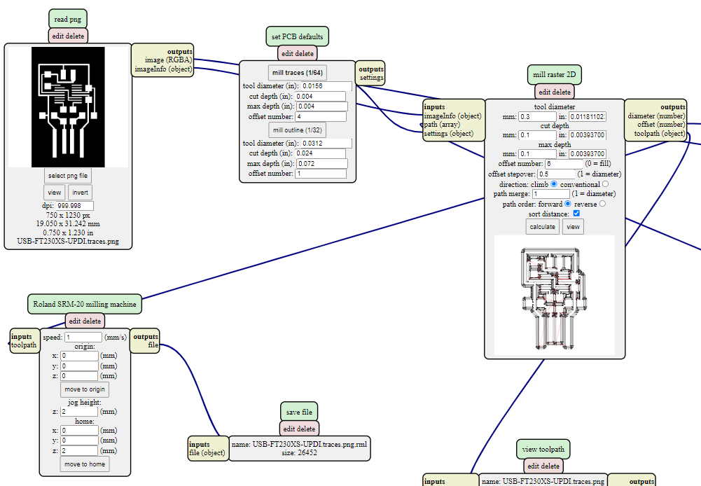
Use the mods to create the .rml files. The parameters are important. Once import the png file, select the tool diameter (depends on the milling bits we use). Cut depth and maximum depth suppose to be the thickness of copper, so we set it into 0.1. Usually 0.4mm for the interior and 0.8 mm for the outline to cut the PCB off. 0.4 mm milling bits should use offset number 4 and 0.3 mm one could use offset number 5-6.
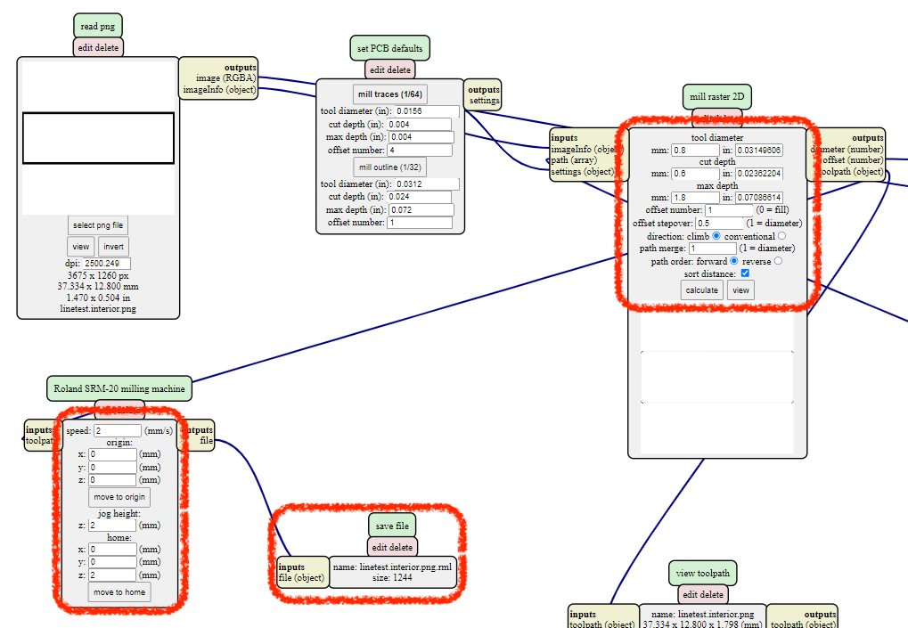
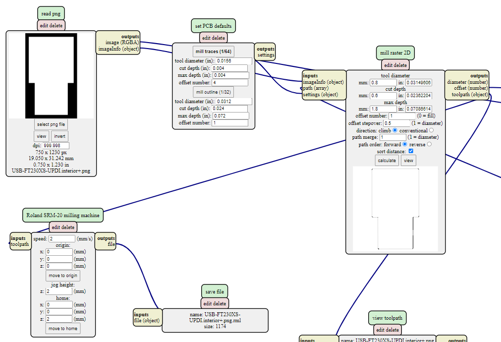
When we cut the outline, the tool diameter change to 0.8 bit and the cut depth should less than the tool diameter and 0.6 is 75% of the bit, which is perfect. The thickness of the coppered board is 1.8 so that is the maximum depth. Once it’s all set well, then click the calculate button.
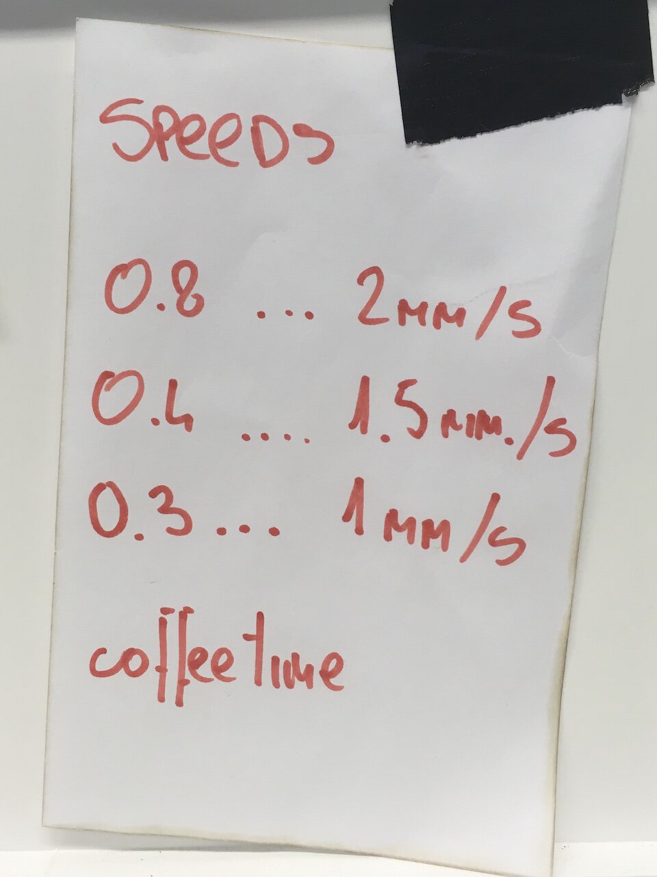
The speeds of each size of milling bits need to follow the instruction, otherwise, the bits would be broken. The percentage of the speed should always start from 20% to 100% in the manual tab.
! Start to cut
After setting all the parameters carefully, just click the cut button bravely!
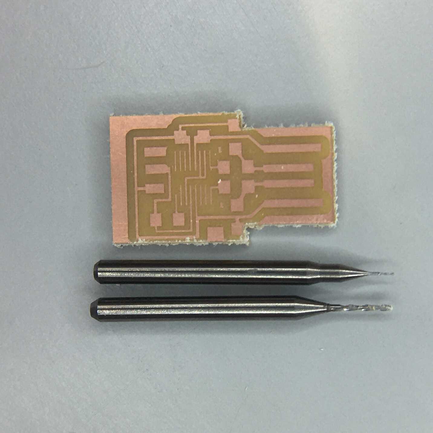
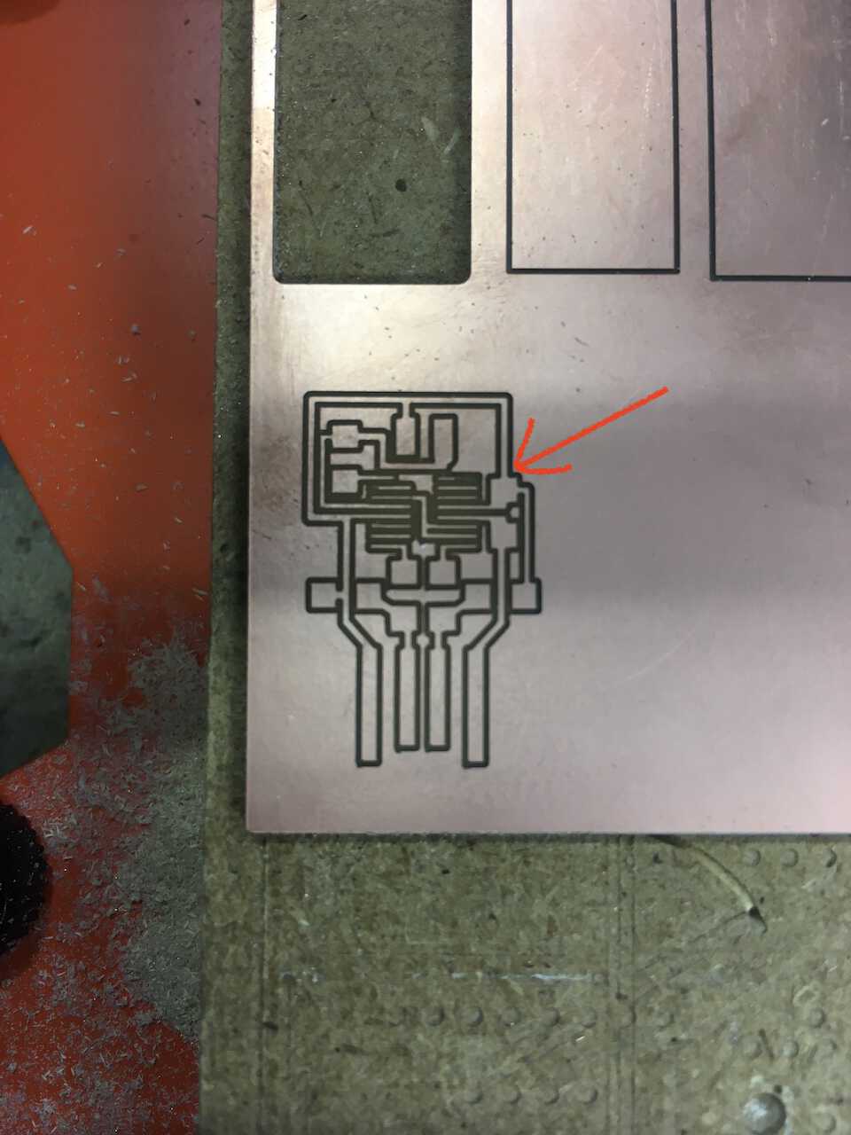
These are what we got after experimenting with 0.3mm and 0.4mm milling bits, the smaller one obviously can do more accurate milling.
!? Mistakes
While I was milling the group assignment with a 0.4mm bit, it was broken. After the double-check with all parameters, it broke second time. :(
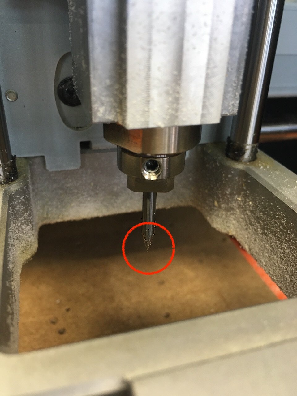
After the discussion with Kris, the problem might because of the uneven base that leads to the bit endures with too much horizontal force. So we relocated the copper board, afterwards the following steps were smoother.
Individual Assignment
To make an in-circuit programmer, I did the same procedure with the group assignment. But I did a small modification to the outline of the USB adapter. From the experience from last year, the adapter needs to be longer to insert into a USB port.
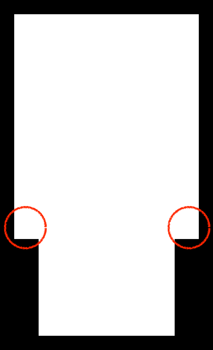 →
→

Import the png files into mods and change the parameters to calculate the paths for the milling machine. Instead of 0.4mm bit, I used 0.3mm one this time.
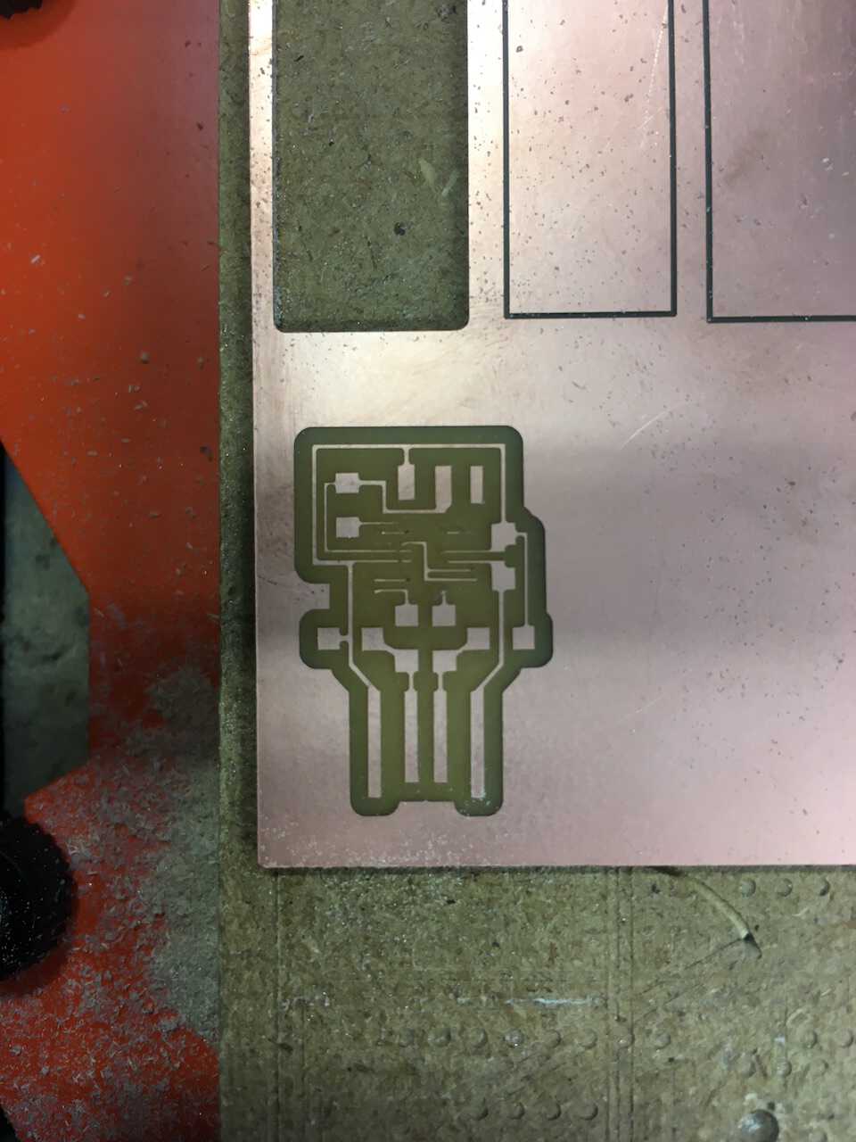
Time to milling, and then I successfully got this!
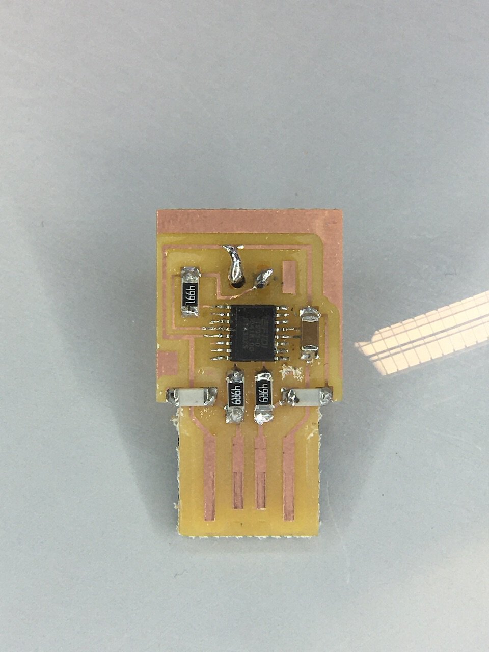
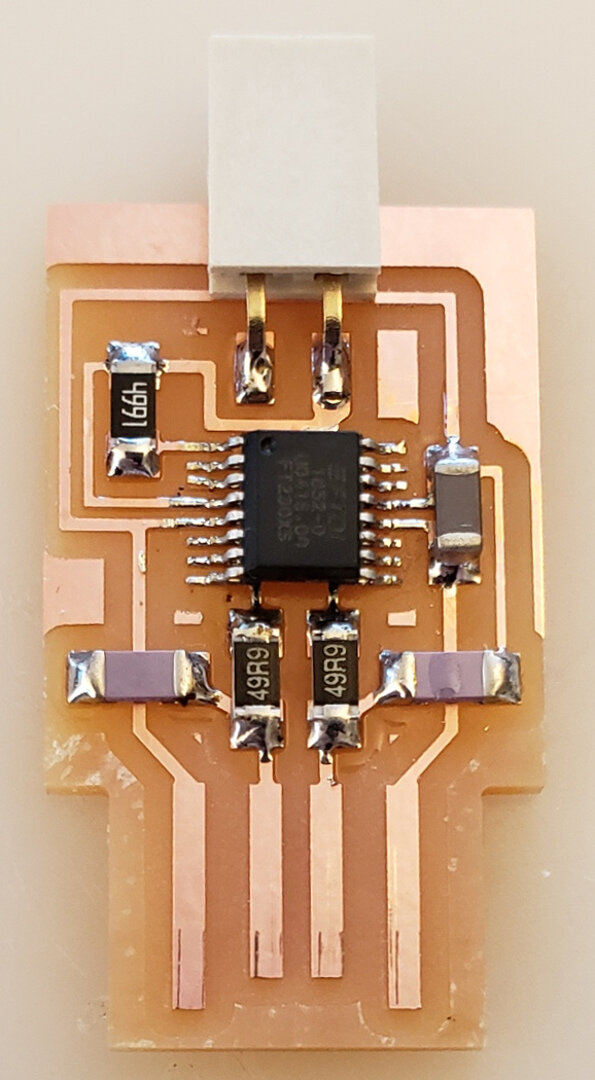
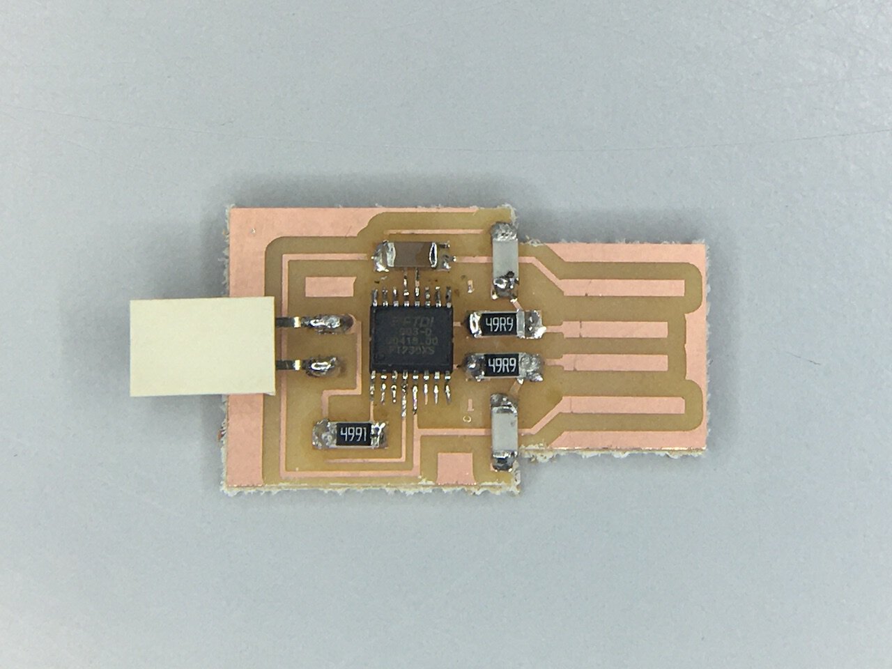
Soldering (Stuffing)
Our goal is to reproduce from Neil’s example.
-
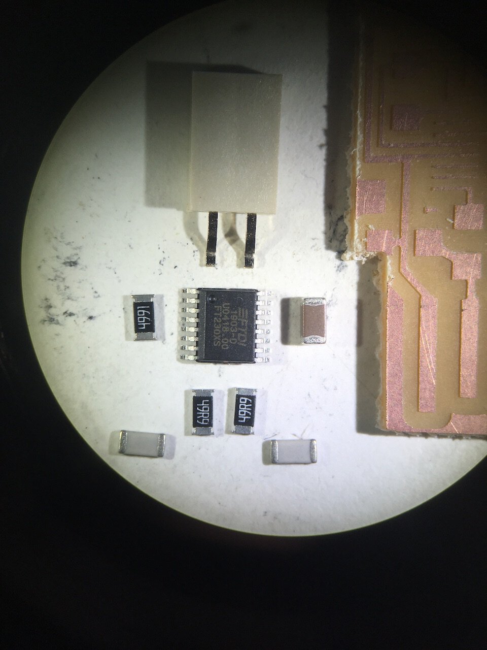
Collect the resistors, capacities, and connector
-
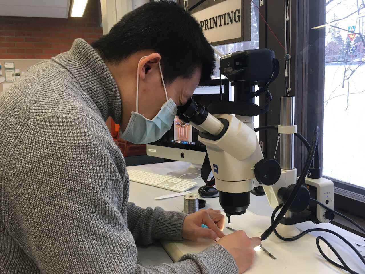
Do it properly under the microscope, and piece by piece
-
Tada!
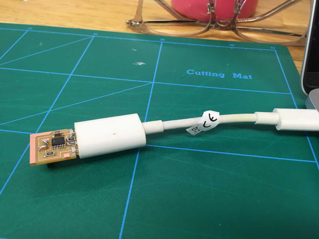
! Let’s test
To prevent the shortcut destroys the port of the laptop, it’s good to use a USB adapter.
-
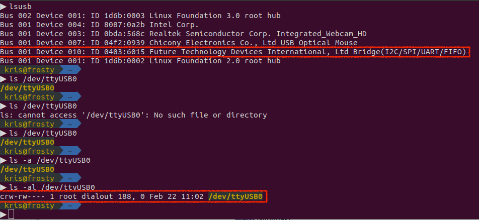
First test on Linux.
-
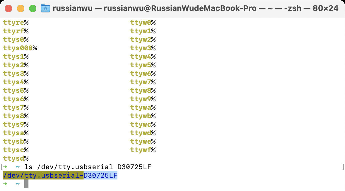
From the result of the second test on the MaxOS, we knew that the USB serial number is D30725LF.
!? Challenges
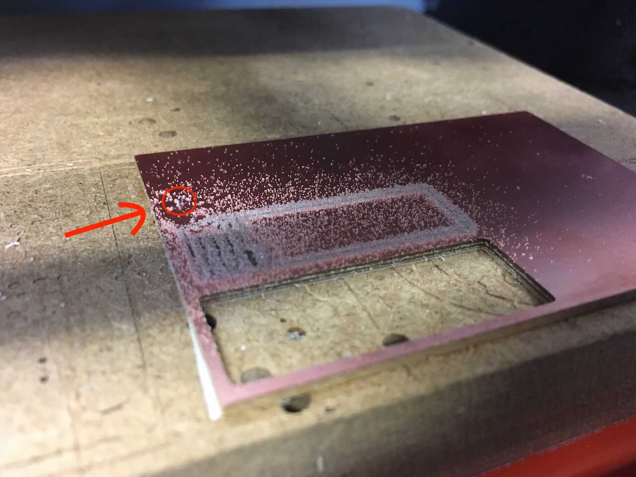
Besides broke the milling bits in the group assignments, I tried with different offset numbers in the setting. However, the 0.4mm milling bits are too thick to remove all the copper. Offset numbers: 1 and 4. Consequently, I used a 0.3mm bit and 5 offset in the end.
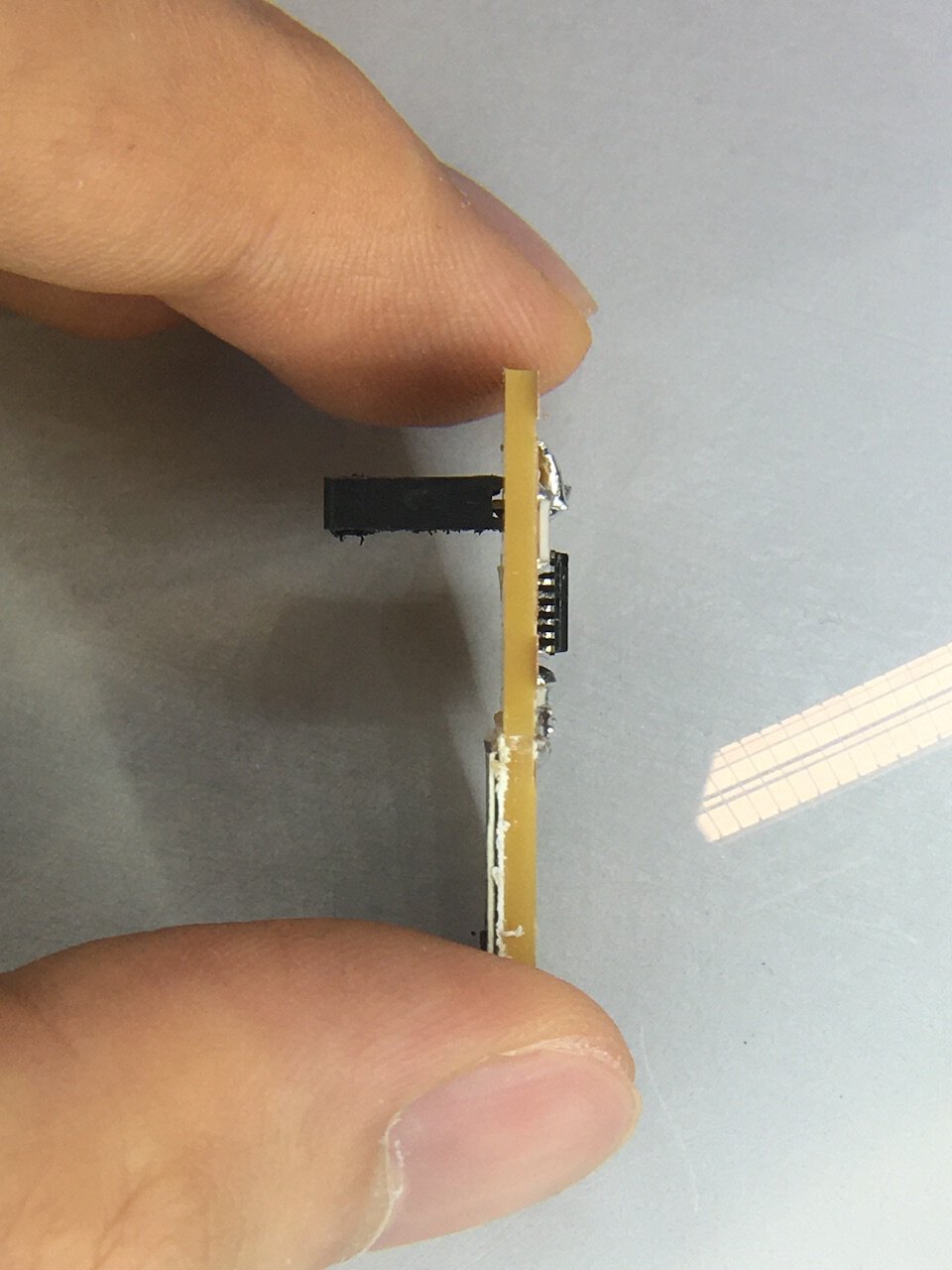
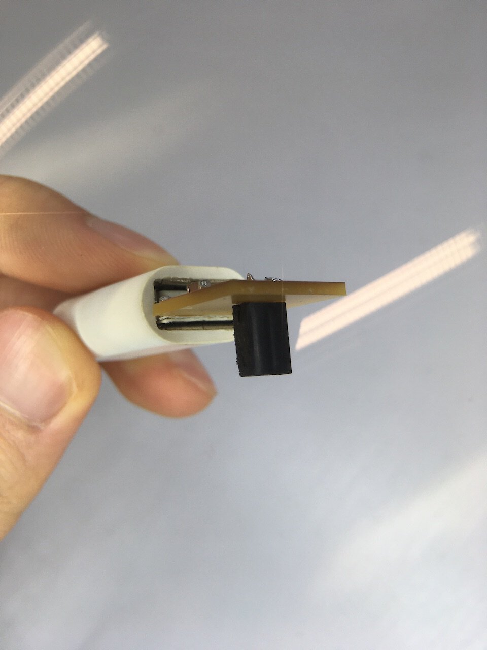
While we were testing the PCB USB adapter, the connector was accidentally broken. So we decided to use the driller from the wood workshop to make the connection points more steady.
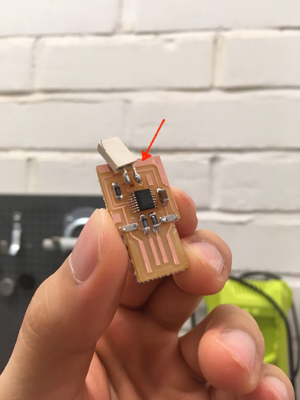
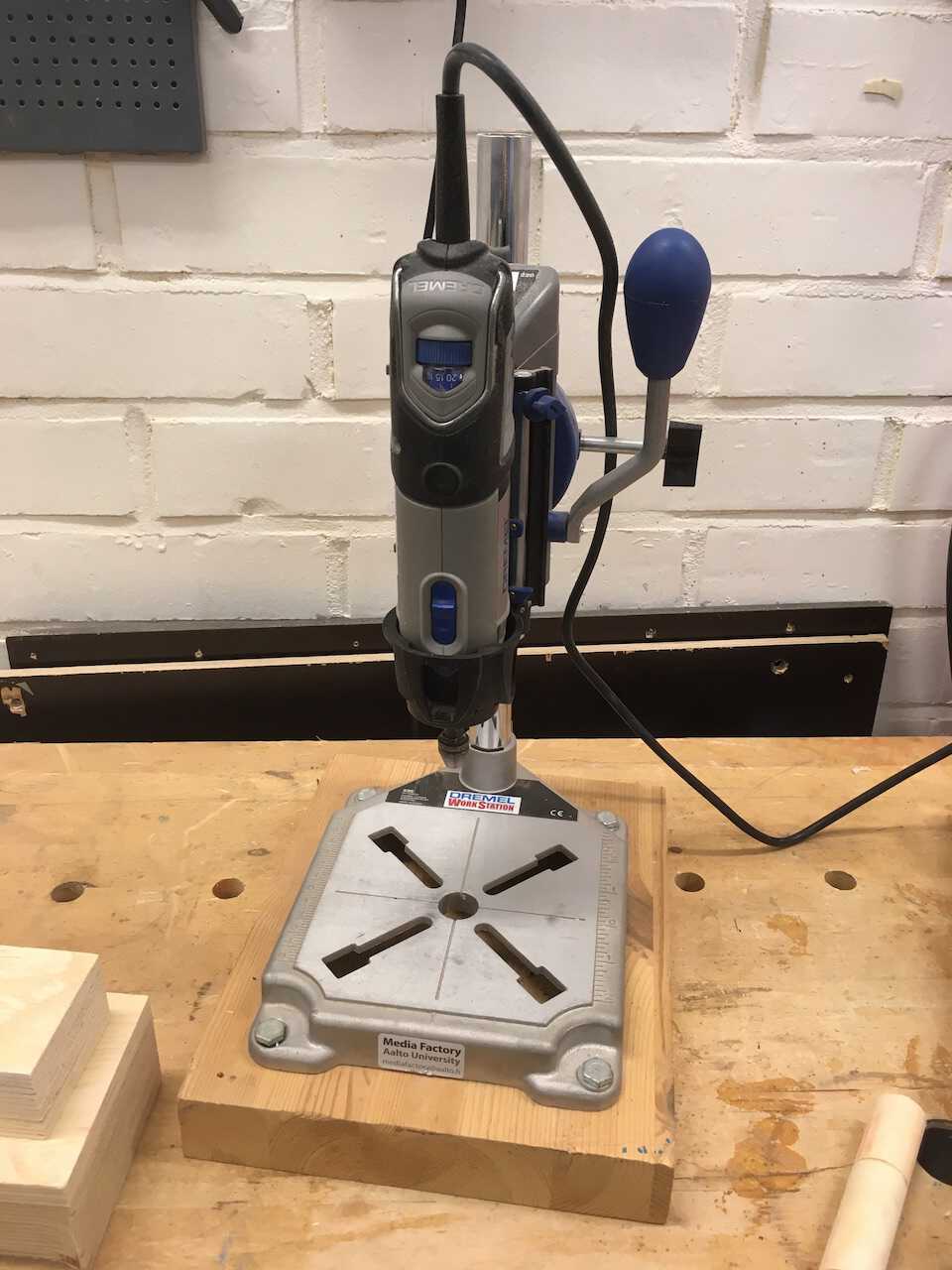
Emergency solved!