Assessment
-
Group assignment
Individual assignments
Learning Outcomes
Have you:
-
Home
Testing design rules on a couple of printers
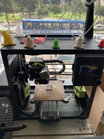
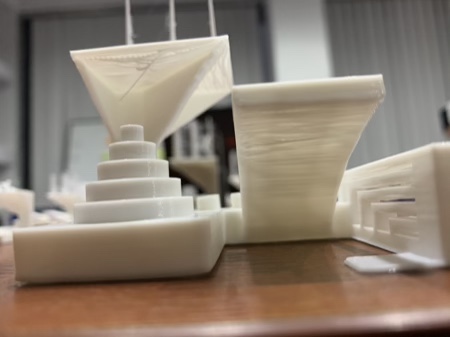
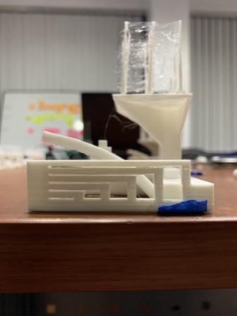
I currently own and work at a 3D printing company, and I have access to many different printers. For this assignment we decided to run a 3d printing torture test through some of the machines in order to see what they are really capable of.
Unfortunately (or fortunately!), we have been very busy at Maker Group Ecuador during this week, and it has been hard to find the time to run the test on all of our machines. In any case, I will update the list as I get the chance to do them.
All prints were made with Maker Group PLA Pro Filament. We used a layer height of 0.2mm with an infill of 15%. While we tried to maintain as many settings as possible equal throughout our tests, some settings vary depending on the printer profile and reflect settings that we have found to work well in the past.
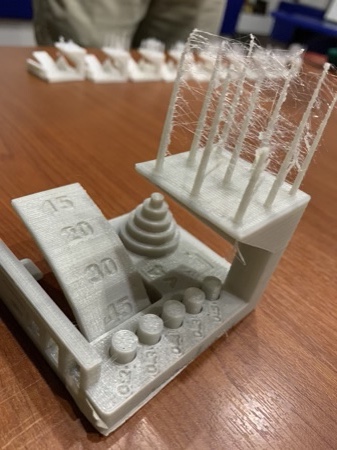
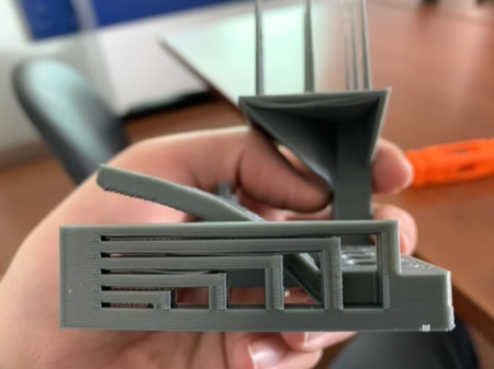
The torture test we used was found on Thingiverse, but was designed in colaboration between Autodesk and Kickstarter in order to evaluate 3D printer projects. There are guidelines for scoring the test results, as well as the file on this github page.
Test results
Printers with no link are pending tests
- Lulzbot Mini 1
- Lulzbot Mini 2
- Lulzbot TAZ 6
- Lulzbot TAZ Pro
- Raise 3D Pro 2 Plus
- Qidi x-one
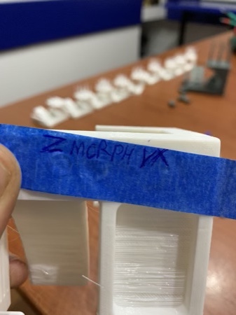
- Zmorph VX
- Monoprice Select Mini V2
- Makerbot Replicator 2
- Formlabs Form 2
- Formlabs Form 3
FDM
SLA
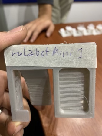
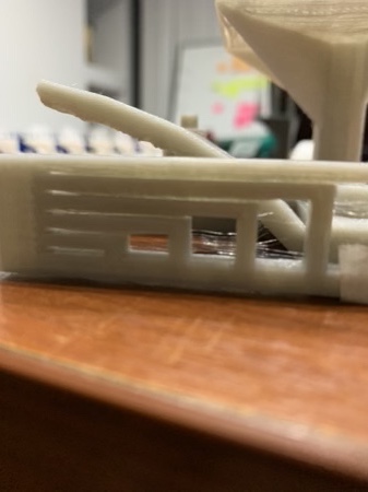
Lulzbot Mini 1
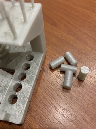
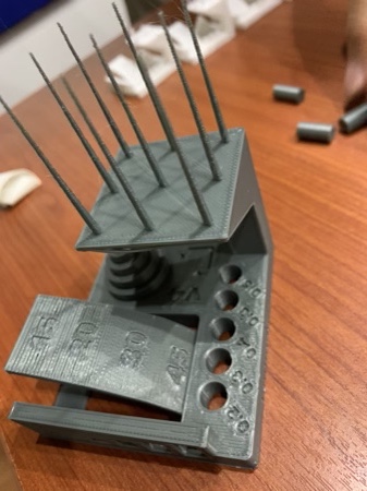
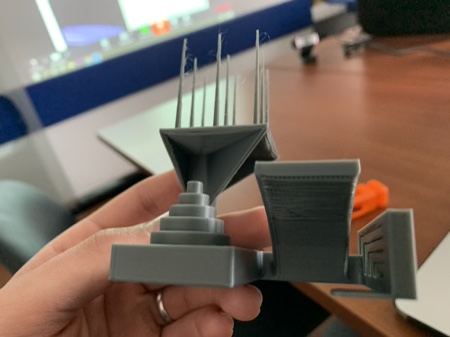
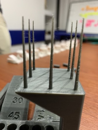
Overall the Lulzbot Mini 1 is still a useful machine. More than anything I would classify this printer as a workhorse. we have had this unit for over 4 years and it continues to be reliable. Overall this unit doesn't produce the most beautiful prints in the world, but it makes up for this with its reliability. I am certain that the mess we see in the stringing and bridging portion of the test mostly points to a need of adjustment in printing temperature, speed and retraction settings. If time allows I will run the test again and post an update. The best performance was seen in the tolerance test, every peg came loose with very little effort, which means that tolerances of up to 0.2 mm can be achieved with proper settings, and I would be willing to say that more could be achieved with some tinkering.
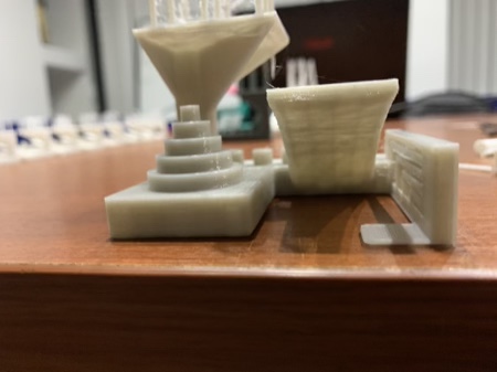
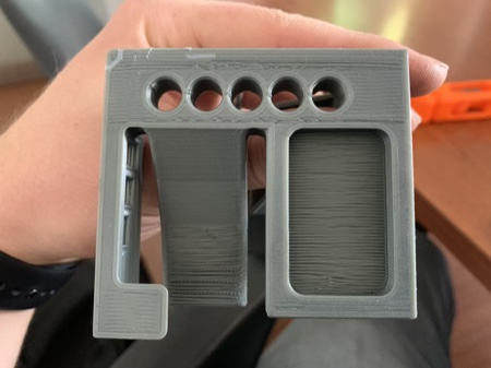
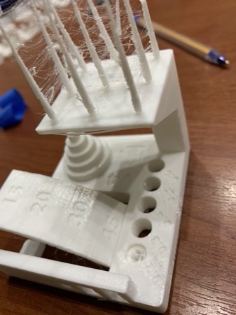
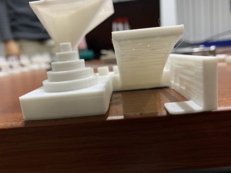
Unsupported Bottom layers
Bridging
Tolerance
Overhangs
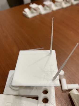
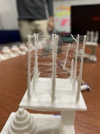
Stringing
Raise 3D Pro 2 Plus
If I had to pick a winner out of the bunch this would be it. This is a well built machine and it shows in how easily it prints. There was virtually no stringing, and both the bridging and overhang tests turned out excellent. These results are probably mostly due to good part cooling design. Surface finish is great as well. The tolerance test released all parts up to the 0.3mm mark with just light pressure. I had to apply force with a pair of pliers to get the 0.2 mm peg out, and I scarred the surface of the print in the process.
Unsupported Bottom layers
Bridging
Tolerance
Overhangs
Stringing
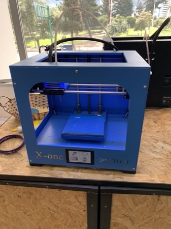
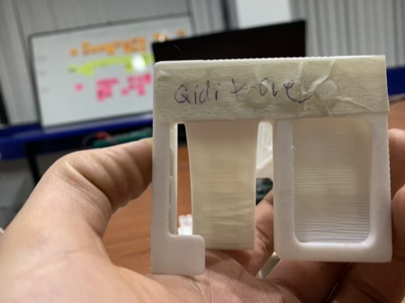
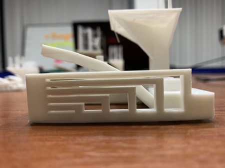
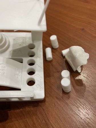
Qidi X-one
This is a surprising little machine, to say the least. Even though it is a lower price point machine I have found it easy to use, and have been constantly surprised by the results. Most of the tests turned out well. The main observation I have has to do with the stringing portion. While the print was still on the print bed, all of the spikes were intact and there were very few signs of stringing. However, the spikes had very poor layer adhesion. This tells me that the precision of extrusion and retraction settings could be better. In any case, they are surprising results for the price point. If I was designing for this printer I would be sure to take steps to make my designs somewhat more robust than I would with another machine.
Unsupported Bottom layers
Bridging
Tolerance
Overhangs
Stringing
Zmorph VX
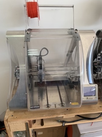
This unit has been a real hit-or-miss in my experience. The machine ships with a 0.3mm nozzle which allows for very high detail and usually a great surface finish, but it also makes the nozzle prone to clogging. While I have gotten some impressive prints off of this machine, I find that the results for the 3D printer function show a lot of room for improvement. If time allows I will clean the nozzle and extruder in order to run the test again. It is also worth mentioning that this is a milti function machine that can be used as a laser engraver, cnc router and paste extruder by switching toolheads.
Unsupported Bottom layers
Bridging
Tolerance
Overhangs
Stringing
I dare you to make THIS on your fancy laser machines
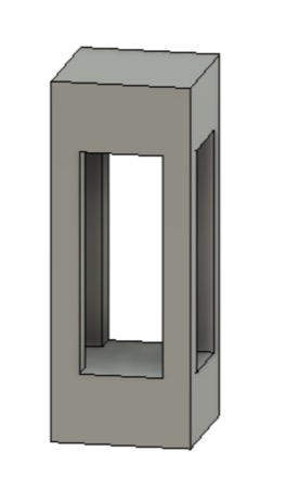
3D printing is a great technology for fabricating complex geometries. It excells at creating parts with internal structures and complex 3D geometries that simply cannot be reproduced via substractive manufacturing processes. It especially excells at producing small quantities of custom objects.
The limitations of 3D printing become apparent when we need to produce a large quantity of identical objects. For one, the materials tend to be expensive. Additionally 3D printing can be a very slow process, especially if a high detail process such as SLA is being used to produce parts. There is also the matter of mechanical properties: it is generally true that a 3D printed part will never be quite as strong as an injection molded or machined part made of the same material. With those limitations in mind, this assignment is all about showing off what 3D printing excells at.
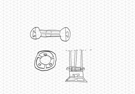
The nature of 3D printing technology allows users to build parts with complex internal geometries that are simply impossible to make using substractive manufacturing methods. When I first got into 3D printing, some of the most fascinating designs I came across were those that printed moving parts in place. I decided to model a kind of fidget toy that could showcase some of these capabilities. I started off by making a quick sketch by hand just to get a feel for what I wanted to make.
I wanted to design a file that contained a prisoner piece, and I wanted to make the ends spin in place by playing around with offset tolerances in my design. I opened up Fusion 360 and began by creating a couple of components. I started by designing the center shaft piece by sketching a rectangle and creating an extrusion.
Then I made a sketch on one of the rectangle's faces and made an inward offset from the outline. This allowed me to hollow out the rectangle by extruding and cutting through the shape. I repeated this process on the adjacent face to get my desired shape.
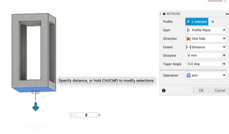
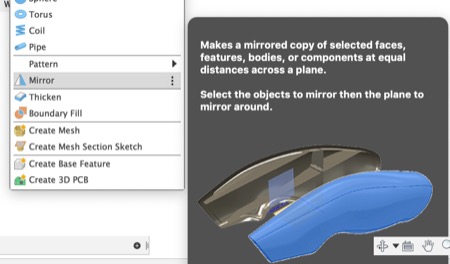
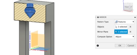
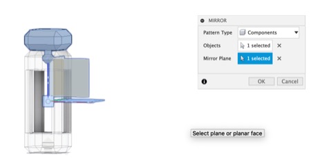
I wanted more material within which I could create the geometry that would hold my spinny parts together. I did this by extruding one side, and then creating a mirror in order to make it symmetrical.
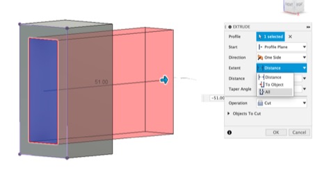
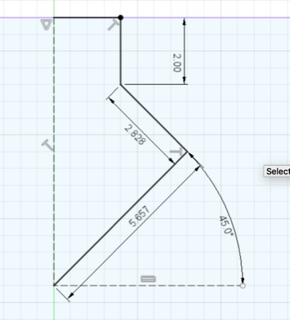
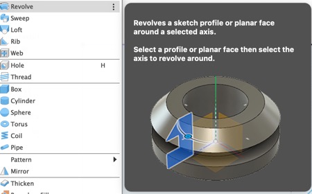
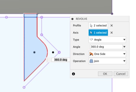
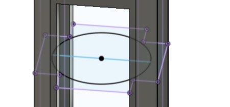
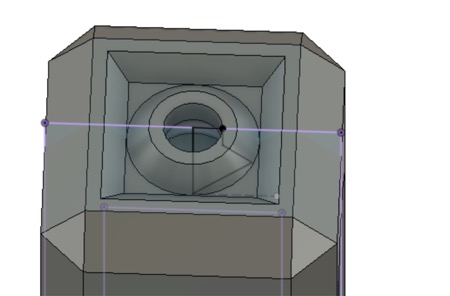
I then created a sketch and used the revolve tool to make a cut in order to make the space that would hold the spinning part's retainer and would keep it attached to the shaft body.
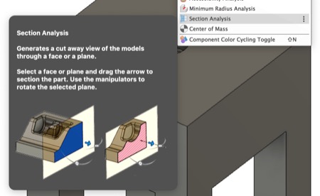
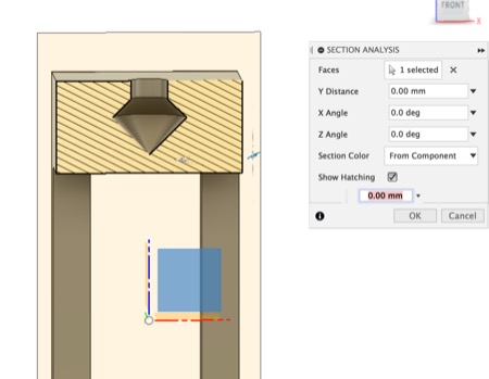
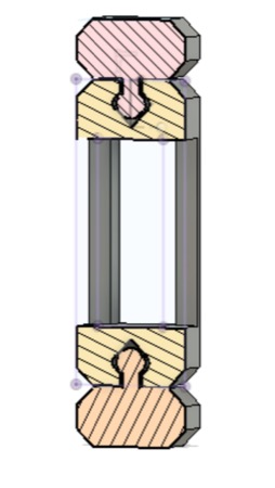
The section analysis tool helps to visualize this by creating a plane and allowing me to visualize the cross-section of my piece.
I wanted to avoid the sharp corners where my lines met, so I went back to my sketch and added a fillet to my shape in order to round it out, and finally I created a mirror in order to have an identical copy at the other end of my piece.
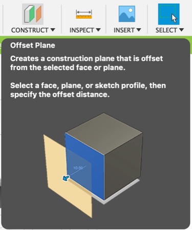
At this point I was happy with the general shape of my central piece, so I moved on to model the spinny parts that would go on both ends. I started out by creating an offset plane 0.4 mm from the end of my center piece. This would create some space between print layers that would affect the layer adhesion at that point and allow the part to break free at the interface between the two parts. I the proceedet to create a sketch and extrude the body of my part from that offset plane.
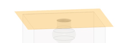
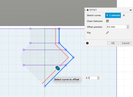
Once I had extruded the main body, I created another sketch on the central plane. For this sketch I projected the geometry from the hole I created and I offset it by 0.5 mm. This part will become the "prisoner" key that will hold the spinny part in place, the 0.5 mm offset is well within the design rules for the printer I will be using to make the piece, and it should allow the part to easily spin freely once printed. I created a revolve from this new geometry and joined it to the main body of the piece I was working on.
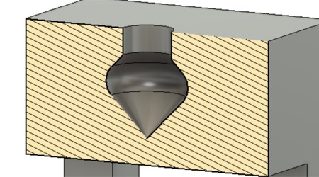
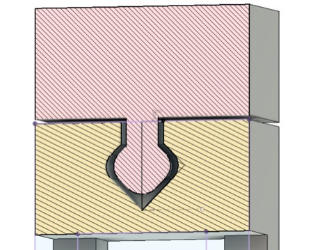
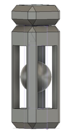
I now had the basic shape of the part, so I double checked with my section analysis. At this point it becomes apparent that a substractive manufacturing process could not make this piece.
It is simply impossible to get a cutter or laser into this part of the model without causing damage to its surroundings.
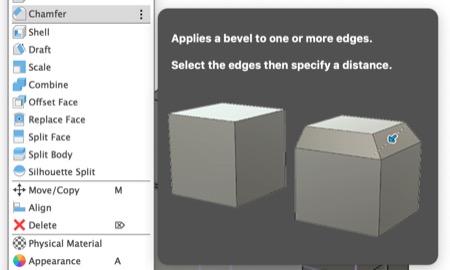
It seemed OK, so I moved on to refine the shape by adding some chamfers to my parts.
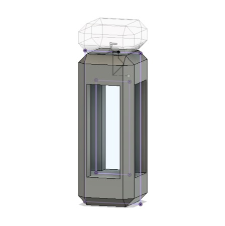
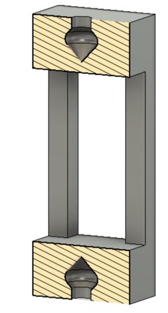
I was content with the shape of my spinny thing, so I created a mirror at this point that copied it to the other end of my piece.
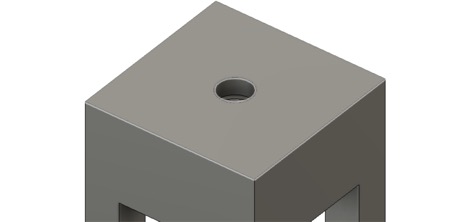
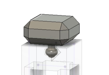
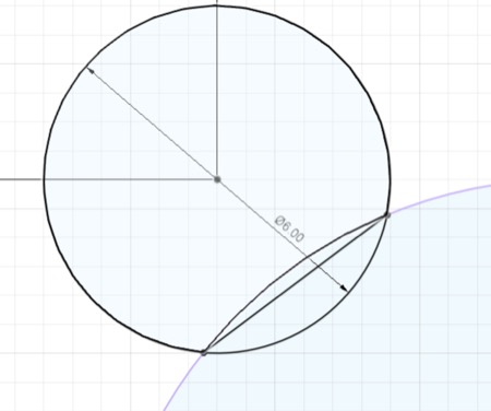
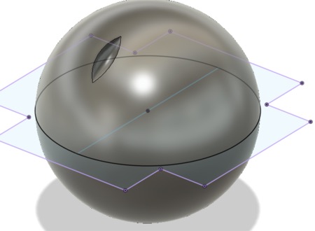
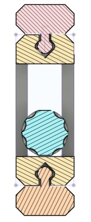
The final component I wanted to add to this design was a sphere that would be held prisoner inside the 4 posts of the central shaft component. I began by creating a sketch on the central plane, making a circle and a revolve in order to make a sphere.
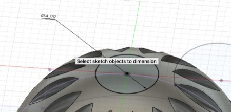
I felt that the smooth sphere would be too plain, so I decided to add a pattern of dimples by adding another circle to my sketch and using it to cut out a dimple on the sphere, then I used the pattern tools to repeat that feature around my sphere.
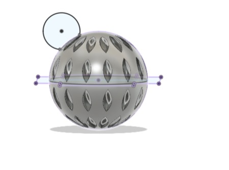
I liked that.
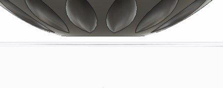
in order to improve printability I added a flat spot on either end of my sphere by adding a sketch and cutting via the extrude tool.
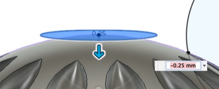
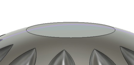
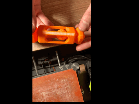
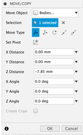
To finish off my sphere I moved it down so that it would print supported on the bottom layer of its prison. I made sure to leave some clearance so that it would not fuse to the central component.
At this point I ran my first test print. I found that the spinning ends fused too well to the central part, so I increased the offset distance as well as adding some new
cuts that would decrease the surface area in contact, this would reduce the adhesion and make it easier to release. The print also displayed issues with overheating on the
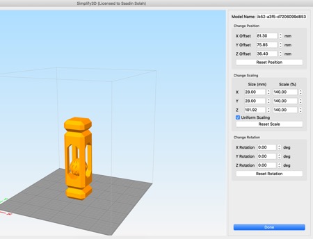
thin features of the central component. I mitigated this by scaling the model up 150% in Simplify 3D.
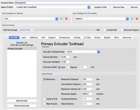
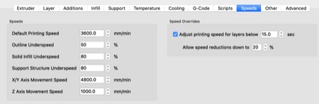
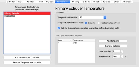
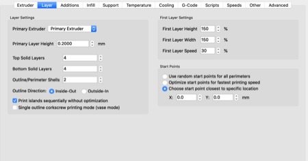
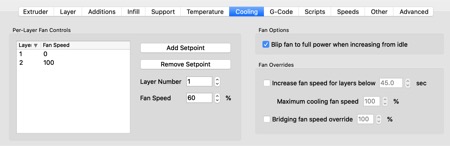
Here are my print settings from Simplify 3D for printing on a Lulzbot Mini 1 V2 printer.
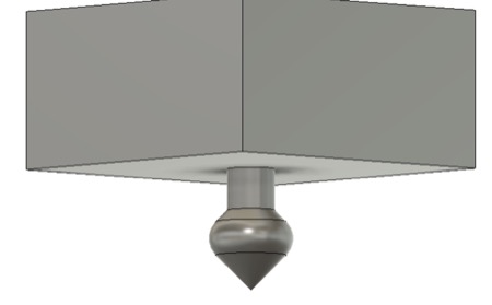
Here is the result: