Assessment
-
Group assignment
Individual assignments
Learning Outcomes
Have you:
-
Home
Laser cutter workflow
The only experience I have had with a laser machine is with a Zmorph VX multifunction 3D printer which uses what felt to me as an anemic laser diode toolhead to primarily execute laser engraving materials. Being a low powered unit, it did not require any cooling or airflow to function correctly. This is my first time using a laser that can cut anything thicker than a sheet of paper.
Our instructor demonstrated the workflow we were supposed to adhere to whenever we used the laser cutter, which I will outline here:
-
In order to ensure a predictable and optimal cut, we must ensure that the mirrors that guide the laser from the
tube, through the lens and to the workpiece are clean. Any contamination on these optical surfaces will work
to disperse the laser beam and will result in an increased beam diameter, which in turn increases the kerf and
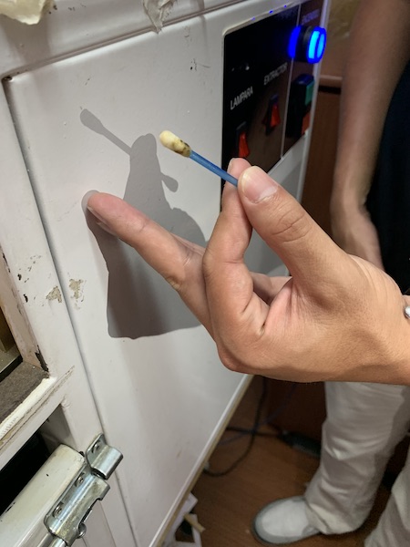
decreases cut accuracy. We inspect each mirror for contamination and if necesary wipe them down with a
cotton swab dampened with rubbing alcohol. The following images show a clouded mirror followed by the process
of cleaning with the cotton swab.
After cleaning, we can see the deposits we cleaned on the cotton swab.
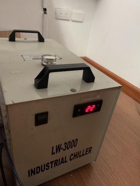
- Powering on the chiller: This step serves to cool the CO2 laser tube and keep it within working parameters. In our case,
room temperature is around 22 degrees C, and we were instructed never to let the chiller temperature (displayed on the red segmented
LED) reach temperatures above 28 degrees C. If the temperature were to reach such a value we should pause the job and allow the temperature
to decrease before continuing the cut.
- The air pump is located behind the chiller in our lab. This is powered on next. The pump creates a flow of air between the tip of the laser and the workpiece. This serves two functions: to clear smoke and fumes along the laser path that could disperse the beam, and to put out any flames that could flare up during the cut.
-
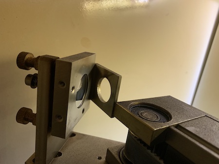
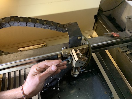
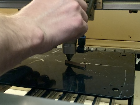
The next step is to calibrate the laser's focal length. In our lab there is a small piece of material
cut to a width of around 6mm. This has been previously determined to be the optimal distance of the laser to the
workpiece in order to ensure a tight beam. To calibrate this distance we loosen the thumbscrews that hold the
lens fixture in place while the calibration piece is placed between the tip of the laser and the workpiece. At
this point the thumbscrews are tightenen and the laser is at a propper distance to function correctly.
-
At this point we can switch on the machine. We power up the machine, as well as the fume extractor and
the interior light. To ensure that the fume extractor vents to the outside, we make sure that the
extractor hose is placed out the window.
-
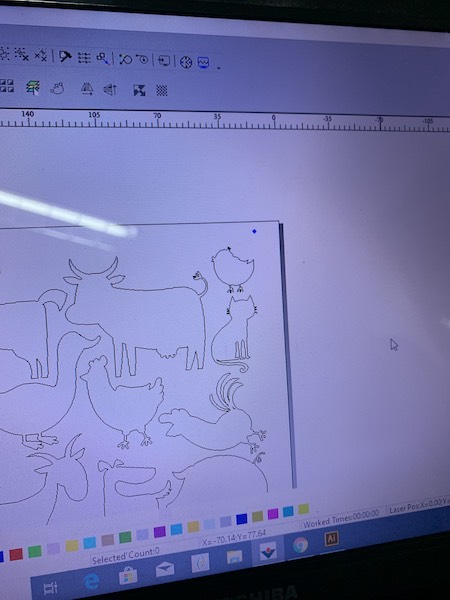
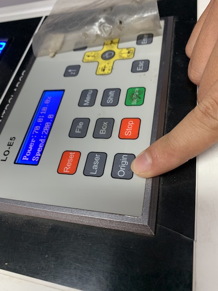
It is important to set an appropriate origin point in order to ensure a good cut. To do this we use the machine
XY jog controls to place the laser head at a desirable origin point for cutting your design. We used Laser Cad
to prepare our files for cutting. In Laser CAD the origin is set at the upper right corner of the design. The
design is imported onto a virtual worktable that reflects the dimensions of the laser cutter worktable. it is important
to fit the design into the worktable, as well as to note the origin point and ensure that the machine origin is set
to a location that will allow the design to be cut without exceeding the bounds of the laser worktable.
-
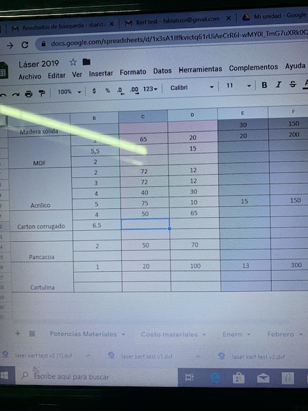
Different materials require different laser power and toolhead speed setting in order to be cut safely and cleanly.
Our instructor provided a spreadsheet containing these values for different materials.
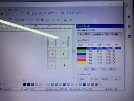
 In Laser CAD you must select the outlines that you wish to cut and assign a color from the bottom of the window to each line. Each
color corresponds to a group of settings that are set in the upper right window.
In Laser CAD you must select the outlines that you wish to cut and assign a color from the bottom of the window to each line. Each
color corresponds to a group of settings that are set in the upper right window.
- At this point all that is left to do is make sure the computer you are working on is connected to the laser cutter and hit the download command in Laser Cad. This sends the job information to the laser cutter. If everything has been done correctly you are ready to hit the Laser button on the machine and begin cutting. It is important to make sure that the cover on the laser cutter is closed to prevent harmful laser radiation from escaping the chamber.
- As a rule, we were told that we cannot leave the room containing the laser cutter while the machine is actively cutting. This is a precaution that is in place in order to react quickly to any fires that could start in the machine from getting out of control. If a fire starts while the machine is cutting, the machine should be immediately paused and the fire should be blown out. We were shown the location of the fire extinguisher in the event that we may need it to put out a larger fire.
-
Once the machine has finished the cut it is important to wait for a couple of minutes before lifting the machine's hood.
This allows the fume extractor to pull any lingering fumes out of the machine. Some materials give off poisonous fumes
while they are being cut by the laser, and the fume extractor ensures that they do not get released into the lab.
After waiting for the fumes to clear, the cover can be removed to take a look at the results. At this point the machine can be switched off. It is important to let the chiller run for a couple of minutes after finishing the jop, as this helps to return the laser tube to room temperature and thus reduces wear. Once cool, the chiller and air pump are switched off.
Kerf Kerfuffle
Kerf is a term that is commonly used when describing cutting tools. From table saws to laser cutters, the kerf is the width of material that is lost due to the with of the cutting tool used to make the cut. We went through a simple excersize in order to determine the kerf left by our laser. I quickly modeled a simple test sketch in Fusion 360.
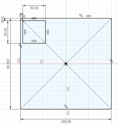
This would have worked if it wasn't for those meddling kids.
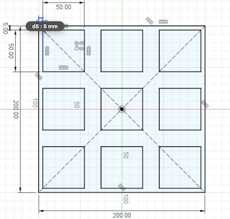
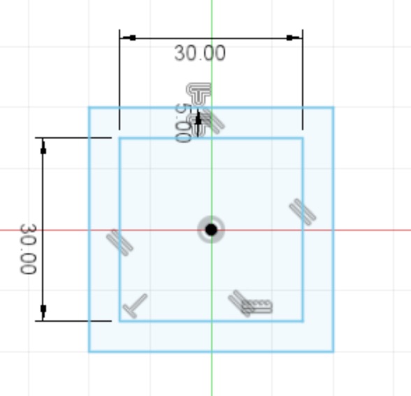
I mean, I over complicated the object and really a single square would have sufficed. Thus I deleted everything and made the following object which was used for our kerf testing.
After exporing this in DXF format, we imported it into Laser Cad and proceeded to create 6 identical copies of the object in order to run tests with various speed and power settings. For this test our instructor, Roberto, advised me to keep the laser power set at 65% while varying the speed for each figure. Extra power to the laser will make it pack a harder punch per millimeter (ppm, if it's not an official unit yet, now it is), while adjusting the speed the laser head moves at will affect the amount of time the material is exposed to the laser light, and thus will have an effect on the cut depth.
The table containing speed and power data for different materials that was provided by our instructor had parameters for cutting 4 mm carboard, but the material I chose to use was 6mm thick. For this reason I added another cell to the table in order to input the values that worked best from my test.
I downloaded the cut file onto the laser machine and proceeded to execute the cut. The following are the results.
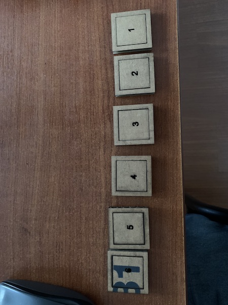
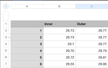
In order to measure the kerf we measured the distance between the edges of the interior square, and the distance between the edges of the hole left by the cutout with vernier calipers. By finding the difference between these values we were able to arrive at a measurement of the Kerf left by the laser beam. It is apparent in the images that the square labeled 1 was cut at higher speed, and the square labeled 6 was cut at a lower speed. This caused the laser to cause excessive burning on the pieces cut at slower speeds, which was reflected as a larger value for the kerf. The following image contains a table with the measured values used to calculate the kerf. From the data it was apparent that using a setting of 25 mm/s as our cutting speed with the power set at 65% would yield acceptable results with a measured kerf of 4 microns.
With knowledge of the kerf value, it was now possible to design with that in mind.
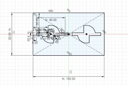
I scream, you scream we all scream for..... parameters?
I think the main reason why I like to work in Fusion 360 is the ability to set parameters that can be referenced and altered throughout the design. Parametric design allows the user to set and name values that can be used as inputs throughout the design process. This is already great for a scatterhead like me, but the real magic happens whe you realize you've made a mistake after hours of working on a project. By setting effective parameters and constraints, fixing mistakes of measurement is as simple as changing a value in a table. If the design uses the value that is changed as a reference, then the parametric modeling software will update any measurement and thus any geometry that is related to it. The process is easier to understand when seen in action.
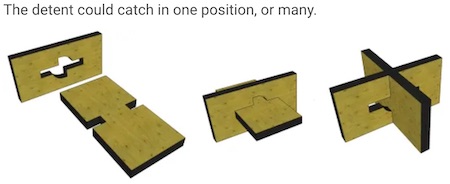
For the individual assignment this week, I decided to design a simple construction kit. I did a couple of searches for digital joinery and I found the following design on the make magazine webpage (click the image to visit the page).
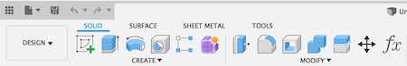
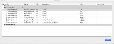
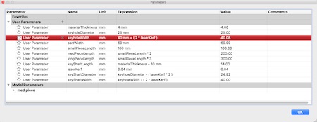
I fired up Fusion 360 and began to set up some parameters. In order to set up parameters that can be easily referenced as I proceeded with my design, I set up a parameter table. This can be done by selecting the function button from the top menu of the design environment.

Once selected, the parameter table window opens. This table allows you to name parameters and set up a value or an expression that you can call from your design by typing the name of the parameter into a dimension input. I started off by creating values based on some measurements that I knew would be refferenced throughout the design, such as the material thickness. I also knew that I wanted to keep the height of my pieces constant, and that I wanted to have pieces of 3 different lengths in my construction set. I added parameters for each of those values, and I made it so that the size of the medium and long pieces depended on the size of the shortes piece by expressing them as a function of my short piece length parameter.
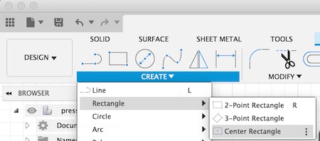
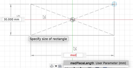
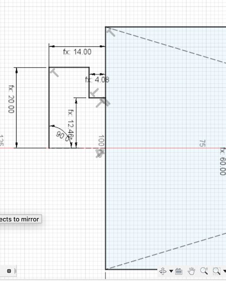
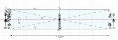
With the first of my parameters set, I was now able to begin drawing up some sketches. I first selected the Center Rectangle tool. I prefer to use the center rectangle because it allows me to keep symmetry with the origin, which makes it easier to use some of the tools in Fusion down the line.
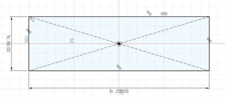
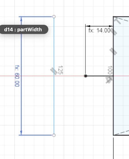
Having parameters with memorable names set up helps me design by making it easier for me to input values as dimensions into my designs. It is harder for me to remember the dimensions I want for a piece, and I feel like I waste a lot of time having to remember where I wrote the value down in order to reference it for the design. In this case, all I have to type in is the beginning of my parameter's name and a dropdown list displays it for me to select. Once selected, the dimension displays as fx:{dimension value}. This means that the dimension of that feature is dependant on one of my parameters, and any change made to the parameter in the table will affect any dimension in the design that references it.
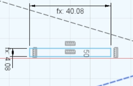
The piece designed in the previous images will be the one that has the key shafts on each side. I added more lines to my sketch and used my parameters to dimension them.
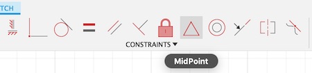
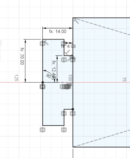
Another important aspect of parametric design is the use of constraints. Constraints allow you to use charateristics of one or more features in your design in order to determine a characteristic of another feature. In this way the constrained features will have a defined relationship that the design program can understand, and it will work to keep that relationship even if dimensions or positions of the features are changed. In the following images I used a midpoint constraint in order to ensure that the line I made always stays centered with respect to the midpoint of the shape it references. It is useful to note that the line changes from blue to black in Fusion 360. This signifies that the line is now fully constrained, which means that every variable that makes up that line depends on another part of the model, and thus the line will update accordingly if any changes are made in the design.

At this point I realized that some of my dimensions were off, so I added a few additional parameters. I included a parameter for my laser kerf. By adding this parameter I can add or substract that measurement to any other parameter or dimension in my model by simply adding it to the expression used to define it. This is especially useful if someone was to decide to recreate this design on a different machine with different kerf characteristics, as it would allow them to account for their specific kerf by simply changing the value in the table.
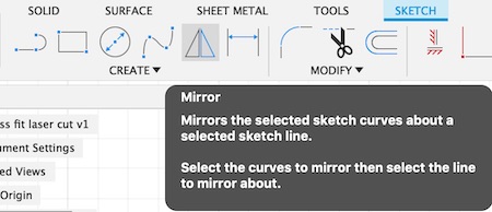
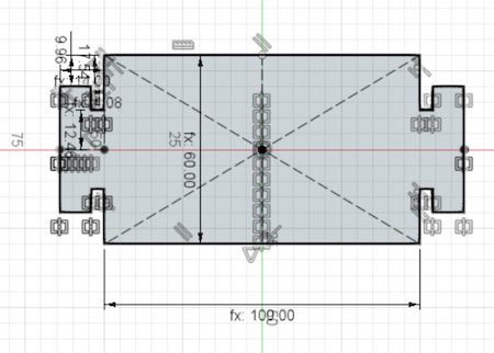
With my updated parameter table I proceeded to design the shaft on the key piece. I first drew out and dimensioned one side of the key. Seing as to this part of the design is symmetrical, I used the mirror tool in order to reproduce the other side of the key. I first selected the mirror option within the sketch create menu. The mirror tool asks for two different inputs. The first is the lines that should be mirrored, and the second is the axis of symmetry. I selected the construction line in the middle. By using a mirror instead of drawing the shape completely with individual lines I can change both sides of my key by modifying only one of the sides. To take additional advantage of my design's symmetry I used the mirror tool again to mirror the entire keypiece onto the other side of the rectangle. This makes it so that all of the keys are referenced from one half of the first key, and any update made to that part of the design will update every other mirrored part.

I decided that I should make 3 pieces of different lengths. The only difference these pieces would have is their length, every other feature would remain the same. For this reason I decided to simply copy my sketch and paste it to a new component. I selected my sketch in the left drop down menu with a right click and selected the copy option. I then right clicked on the main project Icon in the menu and clicked on Paste New. This option pastes what you have on your clipboard to a new component.

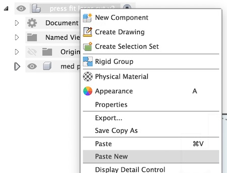
This pasted an identical copy, including all constraints and dimensions into a new component, which I named Short Piece. Since I had already designed the first piece with my parameters in mind, all I had to do was change the dimension that defined the part length to reference a different parameter from my table. This automatically changed the length of my part, as well as positioning the key shafts where they should be due to the constraints that were set up previously.

I did the same for the longer piece.
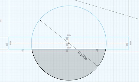
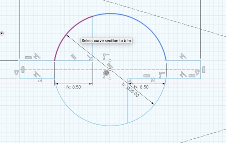
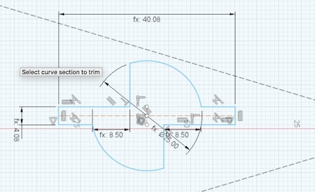
The next step was to design the parts that would have the keyholes that would couple with the key shafts from the previous pieces. I created a new component and began my sketch with a rectangle and my dimensions. I added a few new dimensions related to these key holes in my table and used them to create the shape of the key hole. I used a combination of rectangles, circles and lines to create the shape, and then trimmed off the excess lines.
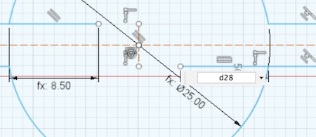
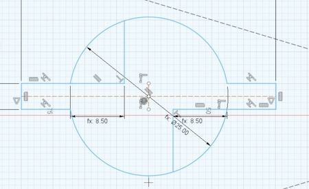
Once the shape was where I wanted it, I dimensioned it from the edges of the large rectangle in order to fully constrain it.

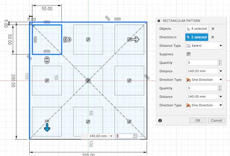
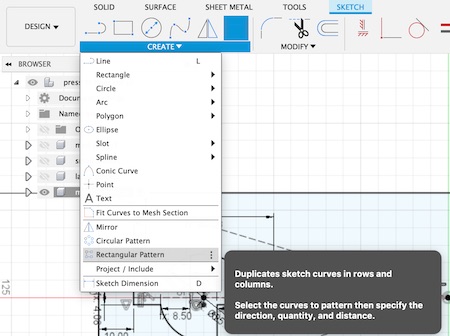
I needed to make several identical copies of this keyhole along my part, so I used the rectangular pattern tool to do it. This tool requires the selection of the sketch lines that you wish to repeat, as well as the directions and distance along which the repetitions will occur. The tool also asks you to define the number of copies you wish to create.

I then repeated the process of copying the complete sketch to new components and adjusting my parameters in order to get them to the dimensions I was looking for.

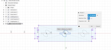
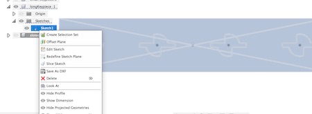
I decided to add two more pieces to the set. I wanted to make a piece that combined the keyhole and shafts, as well as a piece to test out one of the options for making bendable materials on the laser. They keyhole piece was straightforward. I created a new component by copying one of the medium pieces with the key ends. Then I made the medium piece with the kay holes visible and used the Project option to include the keyhole profile into that drawing.
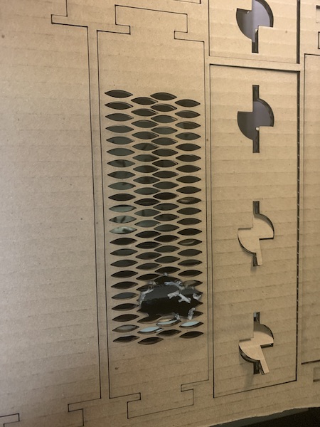
I wanted to make a bendy piece, so I researched kerfing online and I found a pattern that looked good on the Trotec website.
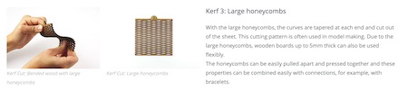
I added another component with the key edges, then I created two slits by mirroring an arc. I made a pattern with both slits that covered most of my piece.

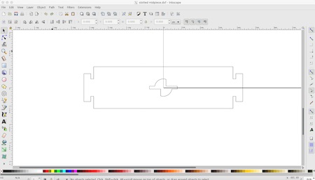
At this point my design files were ready to be exported out of Fusion and into Laser CAD to be prepared for cutting.
I initially exported to .DXF format in Fusion by right clicking on the sketch I wanted to export in the left components
menu.
This exported a valid DXF file, but it exported the files with the construction lines. These lines were tedious to clean up in Inkscape because they were grouped together in unpredictable ways. When I tried to delete the lines in Inkscape sometimes I would end up deleting lines that I wanted to keep along with the undesirable lines.
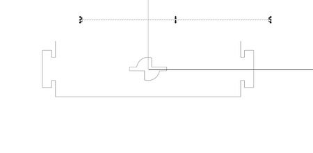
I did some research and found a forum discussing a strategy to export DXF files from Fusion 360 without including the construction lines. The forum can be found here. The strategy involves selecting the profile that you wish to export and extruding it an arbitrary distance. What this does is create a new surface with the desired geometry that does not include any of the construction lines from the original sketch. This surface can be projected into a new sketch and exported as a clean DXF file.

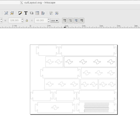
Once I had my clean files I imported them into Inkscape and I set up a canvas that was equal to our laser cutter's worktable size. I used this to place as many pieces as possible in order to cut as many as possible out in a single job.
This is the begining of a small panic and an excellent illustration of how frustration can make a person run around in circles until someone points out the obvious solution .
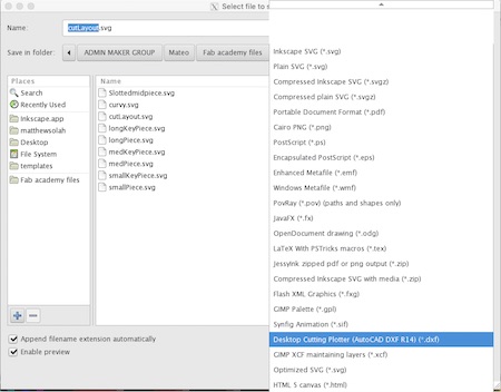
My original intent was to export the cut layout file in .DXF format, but I couldn't find it among the export options in Inkscape. I then assumed that Laser Cad would let me import a .SVG vector file. I was wrong. Laser Cad didn't even acknowledge the existence of my SVG files. After a quick walk to and from the laser cutter, I sat back down at my computer and executed what I thought was going to quickly solve my problem. I imported my .SVG file into Fusion 360 and exported the resulting sketch as a DXF file.

Proud of my design program parkour, I imported the new DXF into Laser Cad.
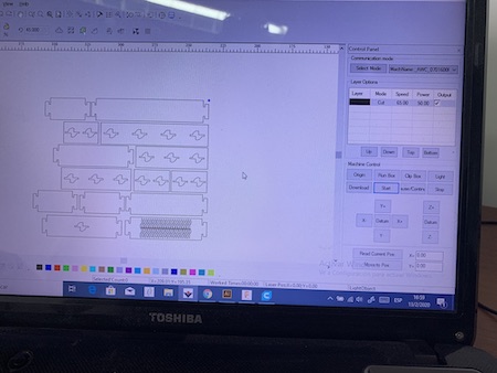
It was perfect, no unwanted lines, clean, crisp geometry. I was happy until I pushed the BOX command on the laser printer. It was assuring me that the lovely layout I designed to fill the 40cm x 60 cm worktable was actually only about 10cm x 15 cm. I initially didn't trust it. I ran the command a couple of times and I was unable to persuade the machine to change it's mind. A closer look at the previous image with eyes that know now what I didn't know back then obviously shows that the imported file is nowhere near the margins of the workspace.
I ran back to my computer and tried again. Maybe the machine would feel bad for me and fix my file for me? No dice.
After witnessing my several failed attempts, my instructor Roberto pointed out that Inkscape does actually export in .DXF format. It was right there in the menu. I just wasn't looking for it's full name. From this day forward, I solemnly swear I will never forget the name: Desktop Cutting Plotter format.
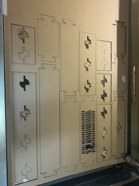
NOW I was ready to finally make my cuts. I followed the procedure and workflow outlined earlier on this page and set the machine to cutting all of my pieces.
Everything went fine. Except for a small fire that started while the machine was cutting the slits in my curvy piece. I managed to quickly pause the job and blow out the flames. I waited for the embers to stop glowing and I continued the job.
I proudly took my pieces home and assembled my kit.
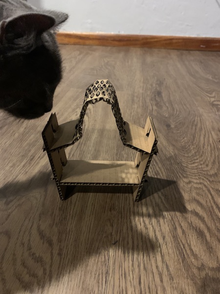

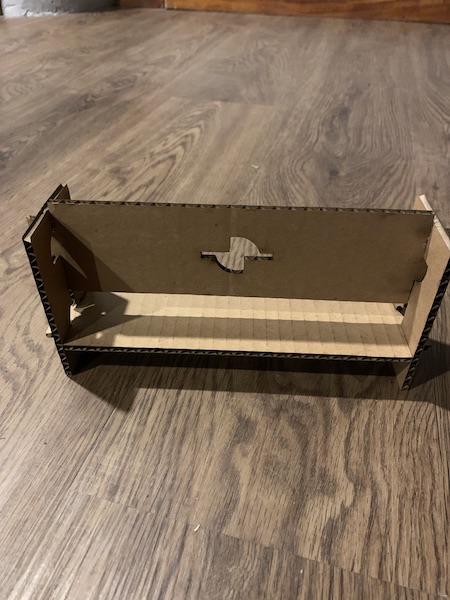
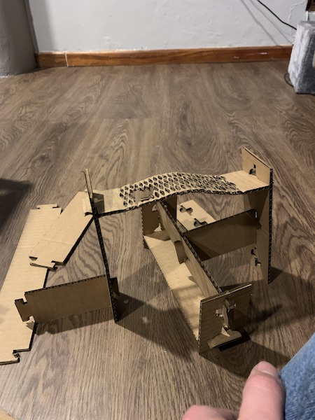
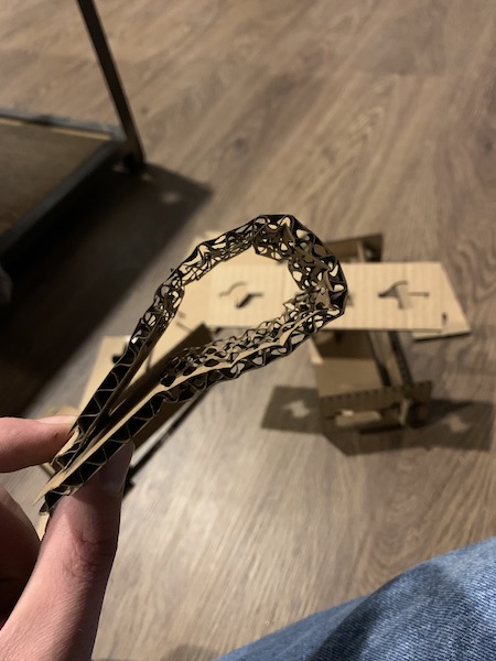
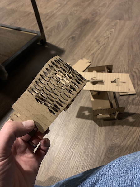
My cat likes the bendy one best.
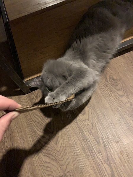
After playing around with the parts I realized that I had made a few mistakes. If I were to make this design again I would take more time to consider the ways that the parts would interact with each other as they are assembled. I did not ensure that the spacing between each keyhole was equal on every part. This lead to some compatibility issues where my partswould fit together at skewed angles in contrast to the 90 degrees I had originally envisioned. There was also an error in the keyhole, mostly due to not double checking my math. The key shafts would fit and lock correctly, but there was too much clearance in the locked position. Fortunately, most of these issues could be resolved by adjusting parameters rather than having to go back and review every part of my design.
This exported a valid DXF file, but it exported the files with the construction lines. These lines were tedious to clean up in Inkscape because they were grouped together in unpredictable ways. When I tried to delete the lines in Inkscape sometimes I would end up deleting lines that I wanted to keep along with the undesirable lines.
I did some research and found a forum discussing a strategy to export DXF files from Fusion 360 without including the construction lines. The forum can be found here. The strategy involves selecting the profile that you wish to export and extruding it an arbitrary distance. What this does is create a new surface with the desired geometry that does not include any of the construction lines from the original sketch. This surface can be projected into a new sketch and exported as a clean DXF file.
Once I had my clean files I imported them into Inkscape and I set up a canvas that was equal to our laser cutter's worktable size. I used this to place as many pieces as possible in order to cut as many as possible out in a single job.
This is the begining of a small panic and an excellent illustration of how frustration can make a person run around in circles until someone points out the obvious solution .
My original intent was to export the cut layout file in .DXF format, but I couldn't find it among the export options in Inkscape. I then assumed that Laser Cad would let me import a .SVG vector file. I was wrong. Laser Cad didn't even acknowledge the existence of my SVG files. After a quick walk to and from the laser cutter, I sat back down at my computer and executed what I thought was going to quickly solve my problem. I imported my .SVG file into Fusion 360 and exported the resulting sketch as a DXF file.
Proud of my design program parkour, I imported the new DXF into Laser Cad.
It was perfect, no unwanted lines, clean, crisp geometry. I was happy until I pushed the BOX command on the laser printer. It was assuring me that the lovely layout I designed to fill the 40cm x 60 cm worktable was actually only about 10cm x 15 cm. I initially didn't trust it. I ran the command a couple of times and I was unable to persuade the machine to change it's mind. A closer look at the previous image with eyes that know now what I didn't know back then obviously shows that the imported file is nowhere near the margins of the workspace.
I ran back to my computer and tried again. Maybe the machine would feel bad for me and fix my file for me? No dice.
After witnessing my several failed attempts, my instructor Roberto pointed out that Inkscape does actually export in .DXF format. It was right there in the menu. I just wasn't looking for it's full name. From this day forward, I solemnly swear I will never forget the name: Desktop Cutting Plotter format.
NOW I was ready to finally make my cuts. I followed the procedure and workflow outlined earlier on this page and set the machine to cutting all of my pieces.
Everything went fine. Except for a small fire that started while the machine was cutting the slits in my curvy piece. I managed to quickly pause the job and blow out the flames. I waited for the embers to stop glowing and I continued the job.
I proudly took my pieces home and assembled my kit.
My cat likes the bendy one best.
After playing around with the parts I realized that I had made a few mistakes. If I were to make this design again I would take more time to consider the ways that the parts would interact with each other as they are assembled. I did not ensure that the spacing between each keyhole was equal on every part. This lead to some compatibility issues where my partswould fit together at skewed angles in contrast to the 90 degrees I had originally envisioned. There was also an error in the keyhole, mostly due to not double checking my math. The key shafts would fit and lock correctly, but there was too much clearance in the locked position. Fortunately, most of these issues could be resolved by adjusting parameters rather than having to go back and review every part of my design.
Learning the Vinyl cutter
I am actually surprised at how much I enjoyed using the vinyl cutter. The machine we have at our lab is a Silhouette Cameo 3. This machine uses a cartesian system to plot cuts on a variety of materials, using a variety of settings to achieve different results. The application that we explored it cutting adhesive vinyl sheets in order to mac custom decals based on a 2D design.
We started off by learning how to load material into the machine. Our instructor pointed out that we should attach the material that we wish to cut to the included cutting surface. This machine doesn't require any special peripheral devices like the laser cutter, so it is simple to just switch on and begin cutting.
We begin by loading the blade into the machine. The Cameo 3 has 2 holders on the print head, in this case we are using toolhead #1 as our cutter.

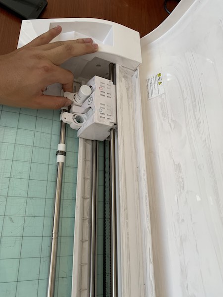
The blade has a system which allows it to vary its depth. This depth is set in the Silhouette Studio software. It is important to set the depth of cut correctly, as this will determine how far into the material the blade will penetrate. We can also set cut force and cutting speed in the software. Cut force will determine how much downward force is applied by the cutter as it moves across the material. Tougher materials will require more force to cut, but using too much force could also damage the material. It is usually preferable to make a tough cut in multiple low force passes than to try and cut through resistant materials in a single pass. This will both preserve the life of the blade and the machine, as well as yield a better surface finish.
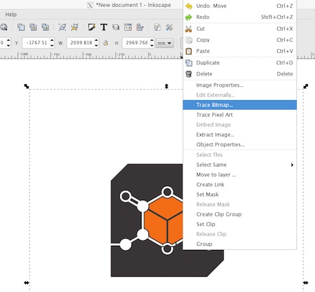
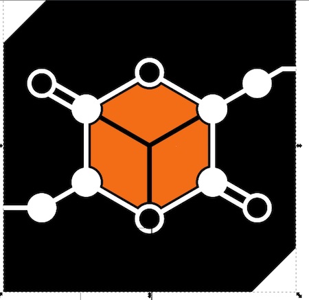
Making a Laptop Decal of my Company Logo
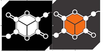
The first thing I needed to do in order to be able to cut my logo out on the vinyl cutter was to convert it from a bitmap to a vector format. I imported the PNG file into Inkscape. From there I right clicked on my image and selected the Trace Bitmap option.
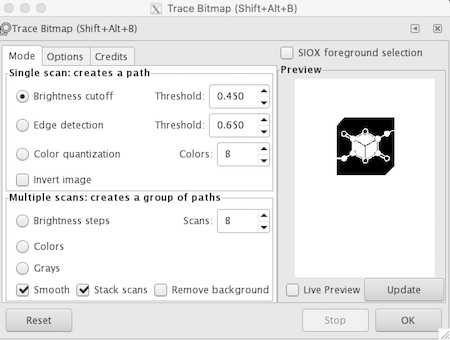
A dialogue box opened up showing a black and white preview of the image. I didn't change any of the settings and I hit OK.
Initially I only saw the grey in my image turn to black. I then tried to move my image and I found that i now had my original bitmap image alongside the black and white vector image.
I then exported this image as a DXF file. This would allow me to import the image into Silhouette Studio and prepare it for cutting on the vinyl cutter.
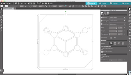
At this point I resized the image and used the software to place it in the area where I planned to attach my material to the vinyl cutter mat.

Next I had to set my cutting parameters. I set them up as best I could by selecting a glossy vinyl from the material preset menu and ran a test cut.

The first time I cut clean through the vinyl and it's backing sheet. I tried two more times, the first time reducing the cut depth to 1 and the cut force by about 30%. The second time I placed both the cut force and depth at their minimum values. There was no change in my results.
It was at this point that I realized that I had been changing the settings for the second toolhead instead of the first, which was where the cutting tool was installed. Brilliant. I fixed this mistake and ran a cut with the following settings.


The test piece cut out correctly, but the cut seemed somewhat shallow. It was hard to separate the inner triangle from the square piece of the test geometry, so I adjusted the cut force for my next test.

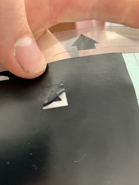
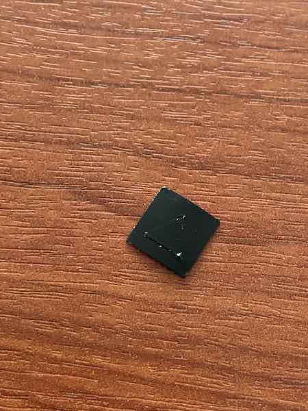
This worked fine for my test. The vinyl peeled off of its backing easily and I decided to use the same settings to cut out my design.

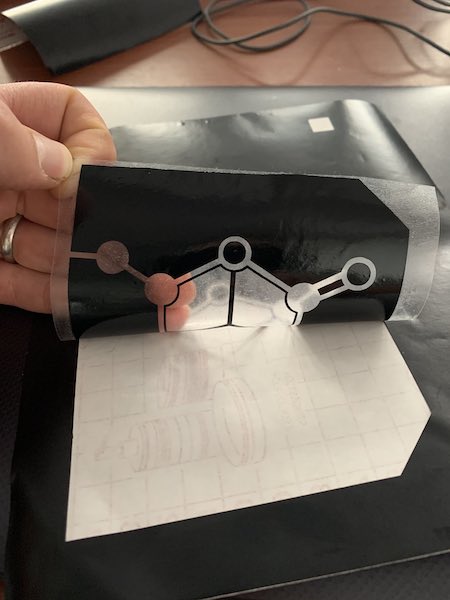
After the machine finished cutting I peeled off the design's negative spaces using a pair of tweezers.

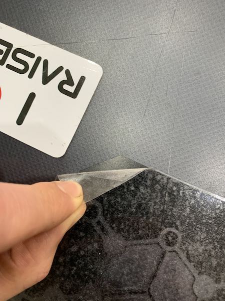
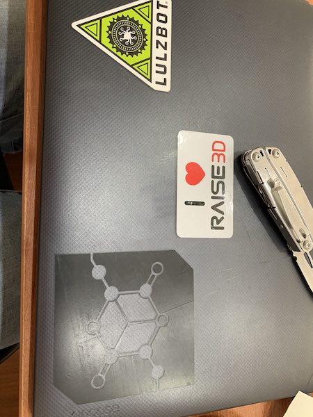
I then used a clear piece of adhesive backed plastic in order to pull my decal off of its backing while preserving the design geometry. The adhesive on the transfer plastic was stronger than necesary, so we were advised to first stick it to our clothing in order to reduce this and allow our decals to release on the surface we intended to place them on. I carefully transfered the sticker to my laptop cover. I had to do this very slowly and use a tool to make sure some of the sharper features of the sticker remained stuck to my laptop.