GROUP ASSIGNMENT
Find out the details of our common work al ZOI Here.
ABOUT OUR MACHINE
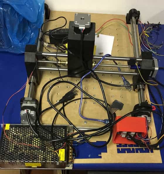
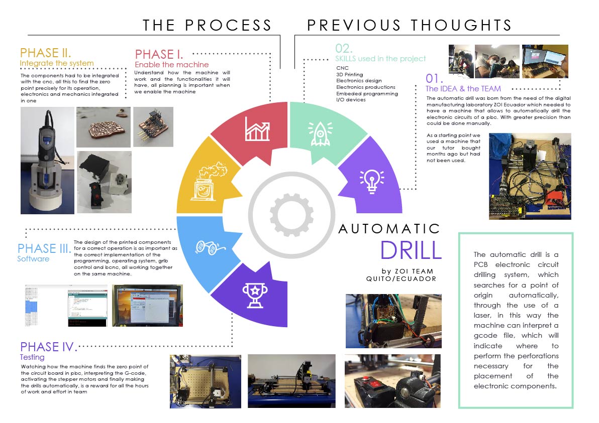
The automatic drill is a PCB electronic circuit drilling system, it searches for a point of origin automatically, through the use of a laser, in this way the machine can interpret a gcode file, which will indicate where to perform the perforations necessary for the placement of the necessary electronic components.
The automatic drill was born from the need of the digital manufacturing laboratory ZOI Ecuador which needed to have a machine that allows it to automatically drill the electronic circuits of pbc. With greater precision than could be done manually.
SKILLS USED IN THE PROCESS
- CNC
- 3D Printing
- Electronics design
- Embeded programming
- I/O devices
Project Pevelopment
For the development of these projects we have divided the work into according to the skills of each team member, in this case I have been in charge of the design and implementation of the cases for the electronic components of the machine. Thanks to his experience in 3D modeling and design, there was no problem in both design and manufacturing.
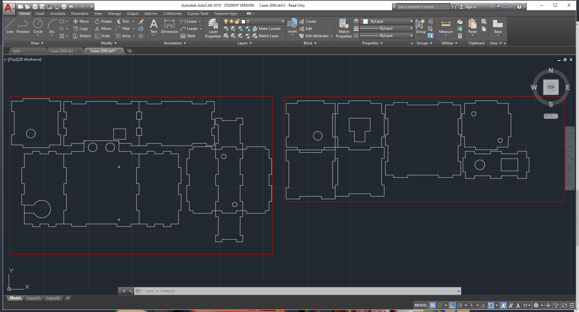
Initially, it was thought to make the manufacturing through 3D printing, however, in order to practice the techniques learned, it was chosen to manufacture through the laser cutting process, so it will greatly optimize the manufacturing times. For the design process, the 2D AutoCAD design software was used, in order to train skills in this software, no other tool such as Maker Case that could have streamlined the design process is used.
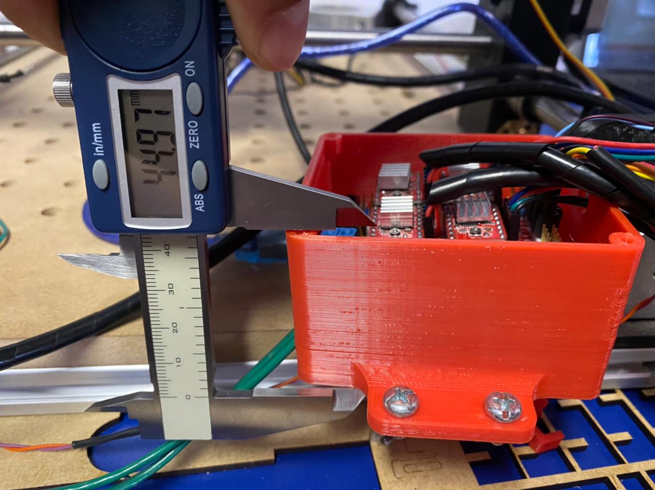
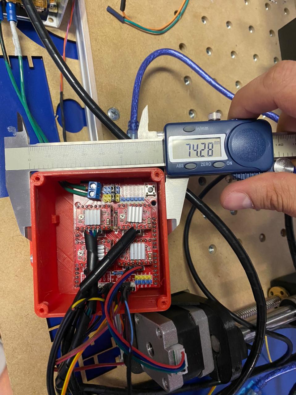
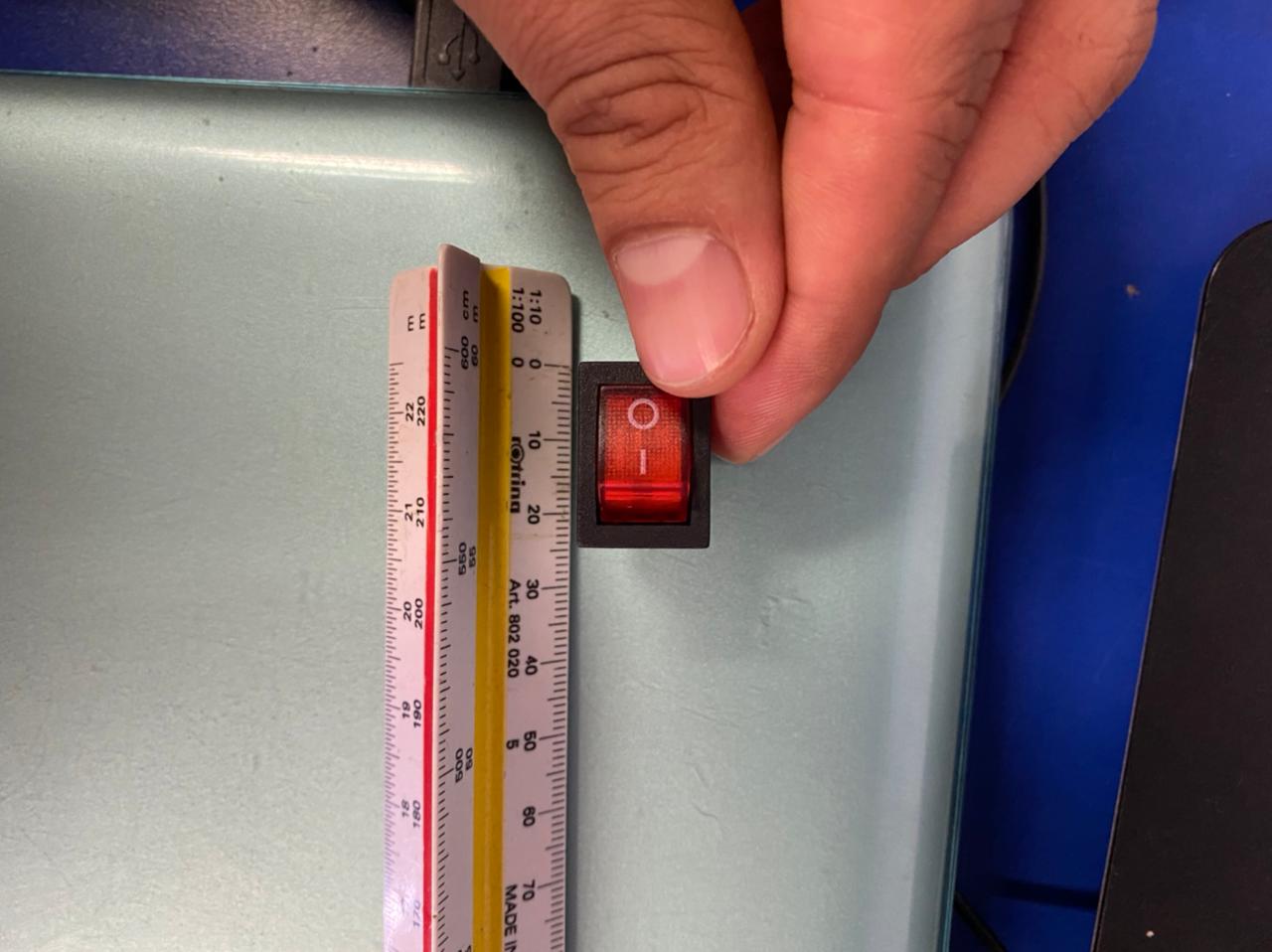
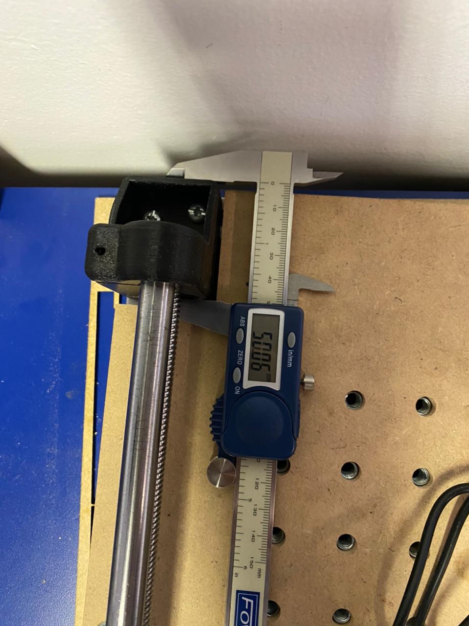
Before proceeding with the design, we obtained the dimensions of the existing components and were able to improve and adapt them to our needs.
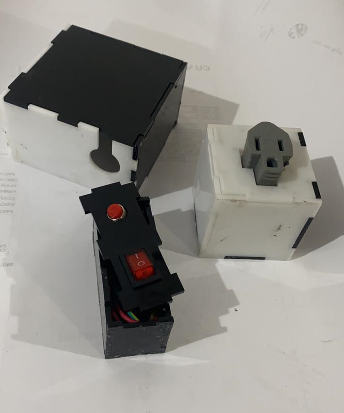
Design in Autocad
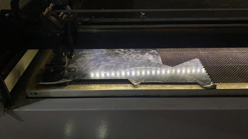
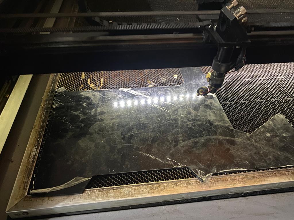
Manufacturing process by laser cutting
Circuit housing completed