Group assignment:
Compare the performance and development workflows for different microcontroller families
First of all, I decided to use the microcontroller Atmega328p and review the Data Sheet
Considerations When Using the ATmega328P
This product contains multiple 8-bit microcontrollers of different shapes, pin configurations, and sizes. Designers should be careful when choosing the proper microcontroller for their project since the members of the product line are not interchangeable. The ATmega328P has two variants of its own, one 5 mm square and the other 7 mm square.
Since memory on the ATmega328P is programmable, this introduces the capacity for software bugs with the potential to impact processor execution. For less experienced programmers or designers, this could make it difficult to distinguish between hardware and software bugs when testing a project. The ATmega328P does not contain a C compiler, so programmers must choose their own. Some C compilers do not contain certain bit definitions in their header files. Without these bit definitions, C code for the registers and memory will not compile, even if the code is correct. Programmers should look in the documentation for their C compiler to determine whether these bit definitions are properly supported. The size of the flash memory boot loader section is modifiable, and the ATmega328P allows code to be read from memory at the exact same time as new code is being written. Since the boot loader section can write to itself, it means it is possible for incorrect code to overwrite the ability for the chip to boot properly. Proper maintenance of this feature allows programmers to modify boot instructions dynamically, but this should only be done with a thorough understanding of how this parallel execution works. This read-while-write functionality is a form of parallel programming, even though it’s only on one chip. Information Link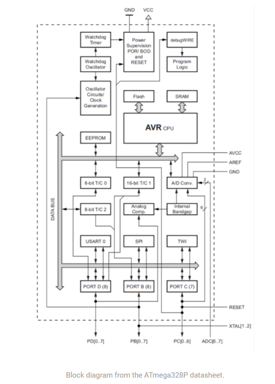
Special ATmega328P Features
The ATmega328P has specialized features for power management: a brown-out mode and six different sleep modes. The brown-out detector (BOD) is not enabled by default, but when enabled, monitors the power consumption in sleep modes. Some sleep modes allow disabling of the BOD, which can save power, but this may also put other operations at risk if power is unexpectedly lost. While sleep mode is usually a simple idle, the sleep modes for the ATmega328P distinguish between idle, noise reduction, power down, power save, standby, and extended standby. Each of these states rely on different stimuli to know when the chip should wake up again.
All functions of the ATmega328P are optimized for speed, but depending on the type of programming or data writing being done, different operations are completed in different time periods. Assuming nothing impedes the writing operations, the ATmega328P can write or erase data within a time interval of 1.7 to 4.5 milliseconds. This range of time can either be helpful or a hindrance to programmers, depending on how they handle chip interrupts during the writing process. Programmers should not rely on all writes happening in the same amount of time. In addition, programmers should be aware of the many different potential interrupt sources in both the hardware and software of the ATmega328P. This gives fine-grained control over execution and writing but can be difficult to master without the datasheet.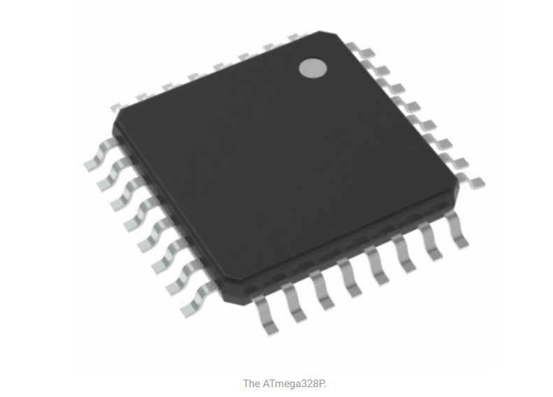
The diiference between an analog pin consist in, analog reads all the values between 0V and 5V. A digital pin reads only 0V or 5V, it reads only the binary language.
VCC: Digital supply voltage.
GND: ground
Port B: is an 8-bit bi-directional I/O
Port C: is a 7-bit bi-directional I/O port
PC6/RESET: If the RSTDISBL Fuse is programmed, PC6 is used as an I/O pin
PortD: is an 8-bit bi-directional I/O
AV: is the supply voltage pin for the A/D Converter
AREF: AREF is the analog reference pin for the A/D Converter
ADC: serve as analog inputs to the A/D converter. These pins are powered from the analog supply and serve as - - 10-bit ADC channels
Analog to digital converter: Is a pin for Inputs, it can be use for both analog and digital signals
Instruction set summary: specify the number of clocks
Electrical characteristics: Shows the minimum and maximum voltages and temperatures that the microcontroller use and support
Individual assigment
Read the datasheet for the microcontroller you are programming Program the board you have made to do something, with as many different programming languages and programming environments as possible.
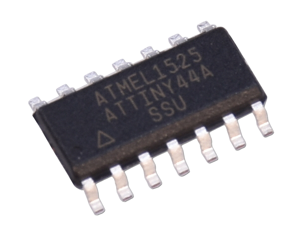
For this embedded programming assignment, the board developed in the electronic design assignment will be used. This board is based on the Atmel attiny44 microcontroller.
Firstly, I would like to share a video of the board. This will give you a better idea of its features and overall design. Thank you for taking the time to review them!
Before starting to program, the specifications and characteristics of the microcontroller were reviewed in the manufacturer's datasheet.
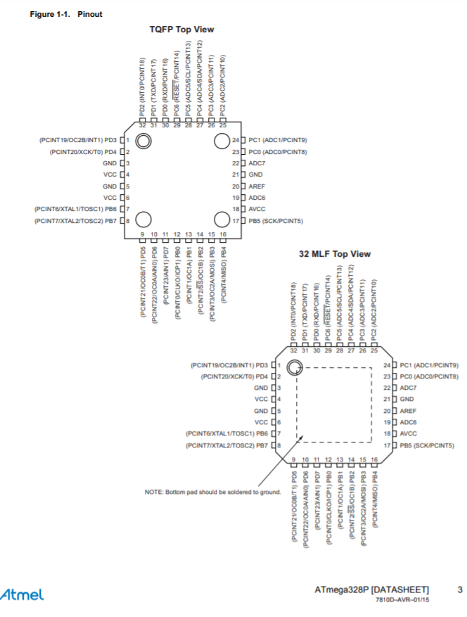
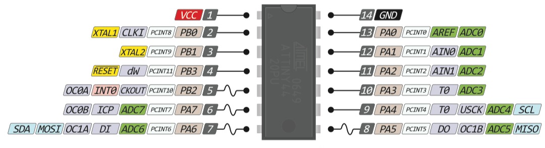
Once we have reviewed the characteristics and technical specifications, it is very important to know the distribution of the input and output pins, as well as the voltage supply pins. We can also obtain this information from the data sheet, however I was able to find a more friendly image on the internet.
PROGRAMMING PROTOCOLS AND GOOD PRACTICES
I don't have a lot of programming experience however collecting and adopting some programming protocols and good practices from other colleagues with experience in this area.
- Write your programs as simple and direct as possible. Keep it simple .
- If you work with a compiler, adjust your options so that it throws as many errors and warnings as possible when compiling, in this way, your application will have fewer chances of getting random errors. Based on the above, check each message to take the appropriate measures.
- In general, an indentation level is used for each block of code (conditional statements and loops are considered as blocks of embedded code inside another, so the indentation is recommended), this indentation corresponds to an indentation that commonly has the value of a tabulation (Tab key) or three or four spaces.
- It is important that the size of the indentations are regular (consistent) and do not vary throughout the code, that is, if the first block occupies a tab as an indentation, the rest of the blocks must be indented with an additional tabulation for each level, with that the reading in any code editor is facilitated.
- It is recommended to declare variables in separate lines, since the description of each variable is facilitated through comments.
- Putting a space after each comma (,) facilitates the readability of the code.
- Do not use variables whose name does not have any descriptive meaning, a variable with significant names allows the reader to understand the context of the code and allows to decrease the amount of associated documentation, since with a readable code and significant names, the code is self-documented . For example, a variable called quantity_requires, has more meaning than a variable called c.
- Comment when it is fair and necessary, use the comments within the functions to describe the variables (only when their usefulness is potentially doubtful) and when there are blocks of code that are difficult to understand at first glance; the excess of comments renders the code illegible.
- It is recommended as a good habit, to add at the beginning of each function, a block of comments explaining the general behavior of the function, so that it can be roughly understood what it does, or is expected to do, as it is provided the search for errors, and unnecessary analysis is avoided in a large number of cases.
- In case of using binary operators (for example +, -, &&, ||, among others) it is recommended to put space at the ends of each operator, so that their presence is highlighted and the reading of the code is facilitated.
- It is recommended in some complex operations, to use redundant or unnecessary parentheses that serve to group expressions within such operations.
- Never forget to initialize counters and adders.
PROGRAMMING WITH THE ARDUINO IDE AND C ++ PROGRAMMING LANGUAGE
ARDUINO IDE
IDE - Integrated Development Environment, is a computer program made up of a set of programming tools. It can be dedicated exclusively to a single programming language or it can be used for several.
An IDE is a programming environment that has been packaged as an application program; that is, it consists of a code editor, a compiler, a debugger, and a graphical interface (GUI) builder. In addition, in the case of Arduino, it incorporates the tools to load the already compiled program into the hardware flash memory.
The Arduino IDE is going to be the working tool with Arduino and it will be necessary to know how it works.
Arduino programs are made up of a single file with the extension “ino”, although it is possible to organize it in several files. The main file must always be in a folder with the same name as the file.
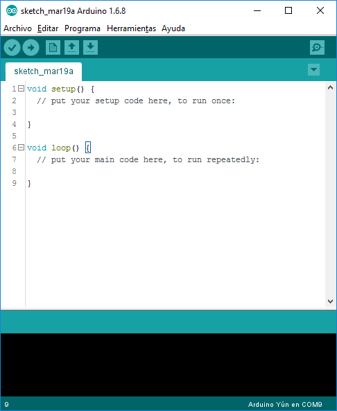
Look of the IDE:
PROGRAMMING ATTINY 44
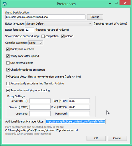
In order to program the attiny 44 microcontroller with the arduino IDE, it is necessary to prepare the work environment since by default the microcontroller is not included
Enter an open file -> Preferences and in additional URLs of the dashboard manager you will see this URL: https://raw.githubusercontent.com/damellis/attiny/ide-1.6.x-boards-manager/package_damellis_attiny_index.json
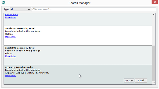
After this screen appears, open (Tools -> Panel-> Board Manager).
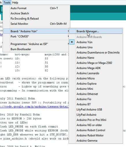
Once "Board Manager" is open, scroll down the list until you see "attiny by Davis A. Mellis". And click to install.
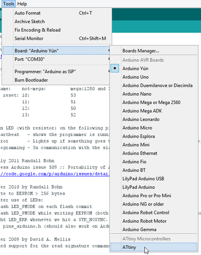
After installing it, you will see a new bar menu, we then select ATtiny:
Now, with everything we have already seen, we will start Programming an ATtiny44
int count;
// the setup function runs once when you press reset or power the board
void setup() {
  // initialize digital pin LED_BUILTIN as an output.
  pinMode(3, OUTPUT);
  pinMode(0, INPUT);
}

// the loop function runs over and over again forever
void loop() {

int button= digitalRead(0);

if(button == 1){
  delay(300);
 count = 1 - count;

  }

  if (count==1){
    digitalWrite(3,1);
    }else{
      digitalWrite(3,0);
      }

}
Program test
OTHER ALTERNATIVES TO PROGRAM ATTINY MICROCONTROLLERS
Although I do not have much experience in embedded systems programming, I have done an investigation of alternatives to program microcontrollers with different development methods and programming languages.
ATOM.IO Y PLATFORMIO
The first option that I bring you is atom.io, a text editor that with its futuristic air and its user interface makes it a pleasure to use.
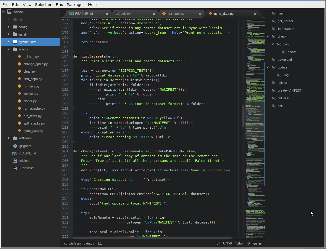
If you add the Platformio plugin to Atom.io, you will have a light but powerful tool for creating robots and electronic prototypes using Arduino or other microcontroladores AVR.
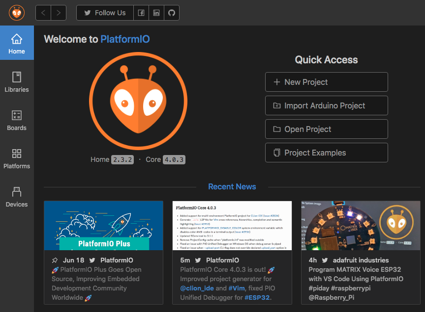
You can download Platformio ide and start using it today, it is an IDE built on GitHub's Atom and Microsoft's Visual Studio Code.
The compilation is also really smooth, and you will be able to select the board and port options similar to the Arduino IDE.
ECLIPSE IDE FOR ARDUINO
Another set of alternatives for the Arduino IDE are Eclipse and Netbeans, both of which are similar in terms of development environments.
They are usually a bit more complex and tedious to start with, but they provide many tools that will come in handy when creating software.
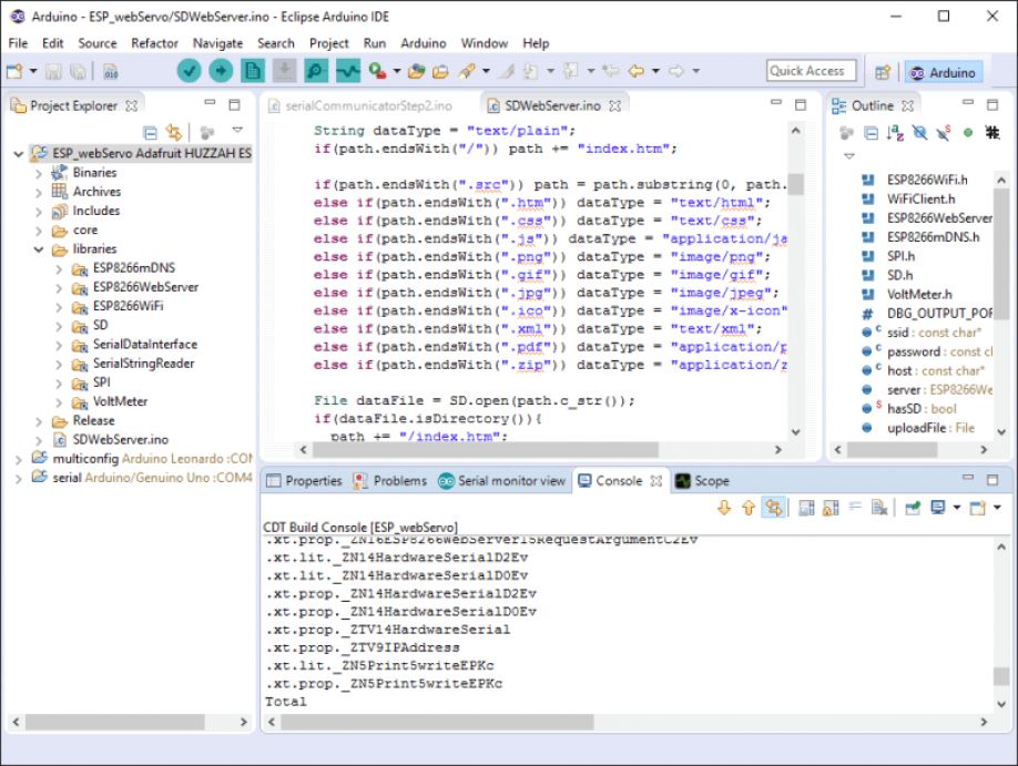
Eclipse and Netbeans also support compiling and uploading code to the Arduino microcontroller.
All you need to do is configure the IDE to allow uploading of the sketch to your board.
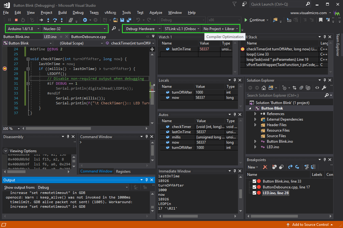
VISUAL STUDIO for MICROCONTROLLERS
A third alternative is Visual Studio. There are premium versions of Visual Studio, but you can also get community developer licenses for free. Although it is a Microsoft IDE, you can use Visual Studio on both Windows PC and Mac.
Conclusion
- Designing the tracks on the computer it is necessary to take it easy, for me this was one of the biggest drawbacks in this process.
- It is not necessary to be an expert in the use of digital tools, it is advisable to review the information of previous students who had similar problems.
- To make the cut in the CNC milling machine the best option is to do a test before applying the cut, especially if you have never used this machine before.
- After having several problems with programming I took the option of doing the programming in the Arduino simulator and this made the process much easier.