PCB Fabrication

I decided making the FabTinyISP with ATtiny45 in-circuit-programmer using instructions from Brian.
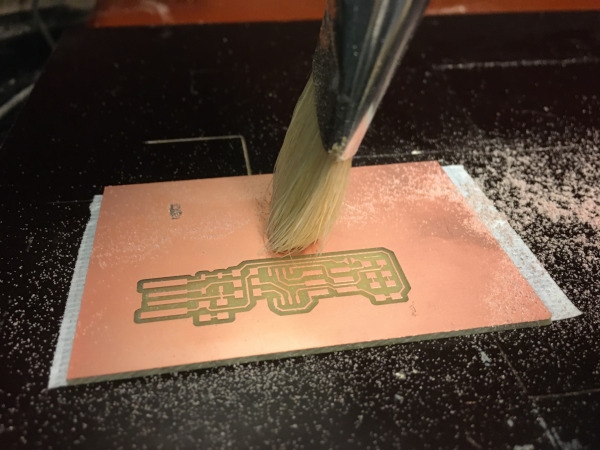
First I downloaded the traces file and opened it in famodules.org. I selected 1/64 traces, chose the right milling machine and pressed “calculate”.
Opened VPANEL (control for the MDX-40) Set Z origin manually then xy origin. Started with a high speed spindle and slow cutting, 11000 and 20% I let it cut for a minute or so and then pushed “view” on the milling machine to check the cutting. The cut was deep enough and clean so I turned the cutting speed up to 60% and then 80%.
Next step was to cut the outlines, I changed the milling bit to 1/32. I set the Z origin manually and used the same XY origin. Opened the cut file in “fabmodules.org” and milled the board in 3 offsets. Then I removed the bit of copper left at the edge of the board in front of the USB contacts with a knife.
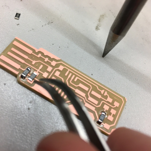
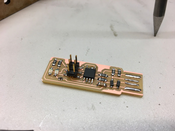
Soldering Components on PCB
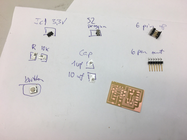
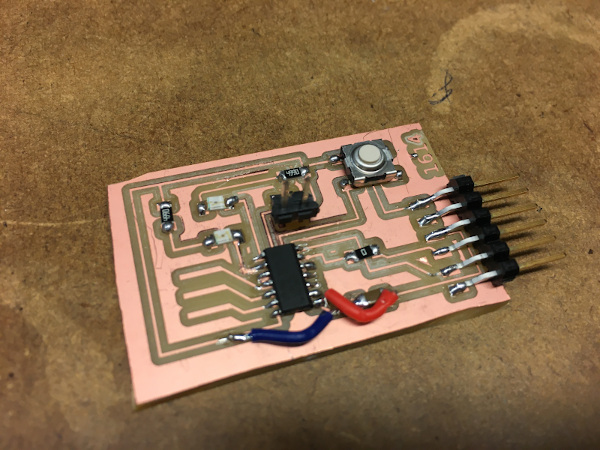
Next I found all the components for my programmer and did the soldering. I ended by putting some solder on the USB connectors for better connection. The board was still too lose in the USB port so I glued a bit of cardboard on the back of it. Then I visually inspected my board and it looked fine to me.
Programming the ATtiny45
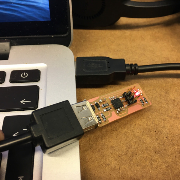
I downloaded the firmware source code zip file. Opened it in terminal then did “make” to create .hex file. I used Atatmel-Ice programmer and started by editing the makefile for the Atamel-Ice. Then I connected the board with USB to my computer and got a red light. Connected the Atamel-Ice to my board and computer, got green and red light so it was connecting. In terminal I wrote “make flash” but got an error, so I added a bit of solder on the pin header. I checked the connections using a multimeter and the soldering of the board seamed to be fine. Still I got the same error.
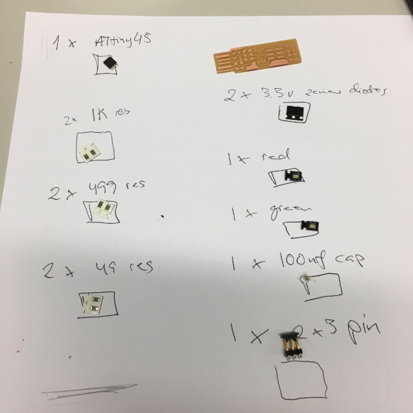
I gave up on this board, maybe it was a USB problem connecting to my MacBook but I was not sure. We got some new AtTiny1614 so I decided to make that one, with 2 leds and a button. I had some problems milling the board but after few tries it worked. There was though a connection missing on it so I did a bit of wiring to get it working.