Test the design rules for your printer(s).
Document your work and explain what are the limits of your printer(s) (in a group or individually)
Design and 3D print an object (small, few cm3, limited by printer time) that could not be easily made subtractively
3D scan an object, try to prepare it for printing (and optionally print it)
Identify the advantages and limitations of 3D printing
Apply design methods and production processes to show your understanding of 3D printing.
Demonstrate how scanning technology can be used to digitize object(s)
(now: Sunday 1st March 2020 11:43 pm):
I genuinely like machines .. but machines don’t like me back.
(now: Tuesday 3rd March 2020 3:30 pm):
3D just opened a door for a whole new world to explore.
In our group assignment we tested some design rules and discovered the limitations of our 3D printers.
For most of the tasks this week, I have mainly used PLA as the filament of my choice to print my 3D designs. However, prior to printing any design, the filament required changing.
The steps to do so on the Ultimaker 3 Extended are the following:
materials >> material 1 >> change.calibrating the level of the build plate is significant in 3D printing as it ensures reliable adhesion of the filament to the build plate, securing the print throughout the process.
If the distance between the build plate and the print core is too large, then the print won’t adhere properly. To the contrary, if the distance is too small, then the filament won’t be extruded.
There are two types of leveling performed by the Ultimaker 3D printer. Active leveling which is automatically performed by the printer at the start of the print, and manual leveling in which the end user manually calibrates the distances of the build plate with the help of the instructions displayed on the screen.
In all of my prints, I used manual leveling and this is how I’ve done it.
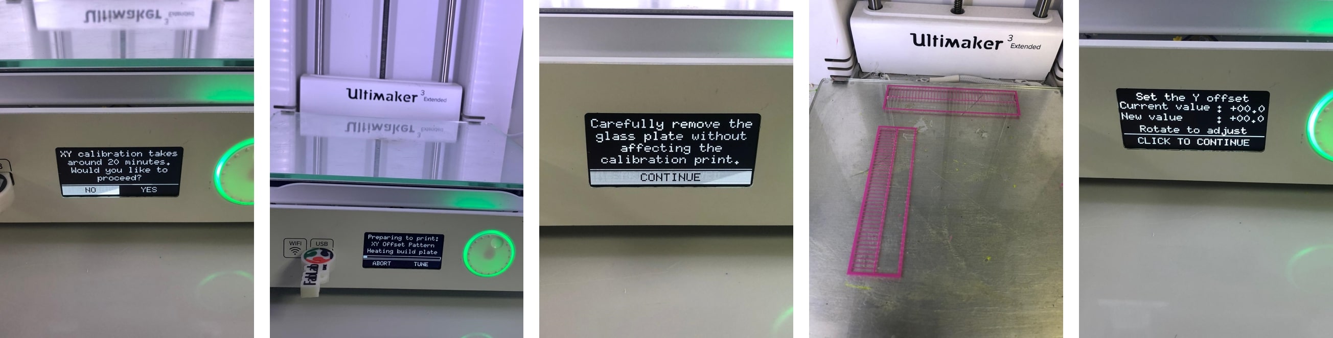
system > build plate > manual leveling.1 mm from the nozzle.One of the problems I faced while I tried Printing my design for the group assignment was the wrong calibration of the Ultimaker 3D printer. The design required a support of PVA, hence adding a second filament.
In the view of my limited experience with the 3D printers, I have spent half a day trying to figure out why the print was distorted and filament won’t extrude properly. The frustration blurred my mind, that I didn’t think of googling the answer, and instead thought that the machine was working it’s best to ruin my trials (silly.. I know!)
By the end of a long day, and with the generous help of a former Fab academy student, the solution presented was the XY offset calibration.
system > maintenance > calibration> calibrate xy offset.
For my very first trial with 3D printing, I used a ready made filament test cube fetched from Thingiverse.
I opened the .stl file in Cura the slicer software for the Ultimaker 3D printers.
I used the basic mode to enter the following values for the purpose of testing:
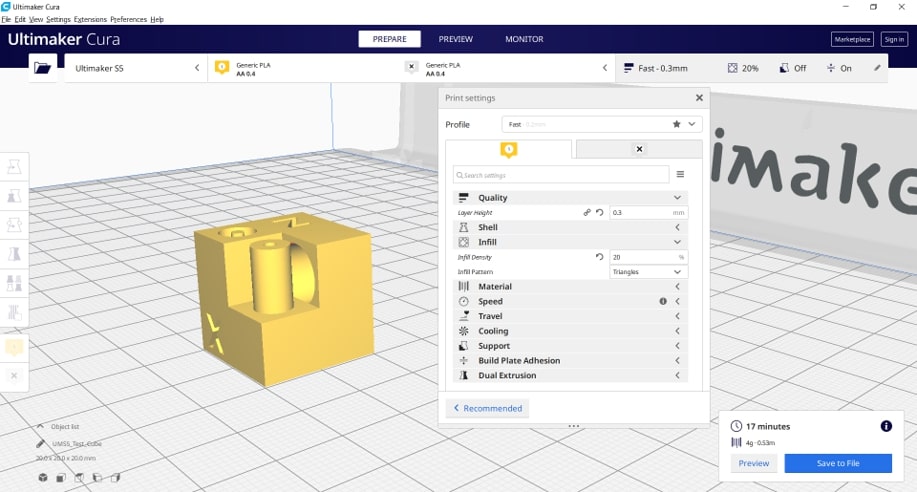
Then I calibrated the building plate using the previously mentioned steps, and headed for the printing set up. To start printing:
printOnce the print is done, I carefully removed it from the build plate and removed the extra brim layer which is a layer that extends from the edges of the design to the build plate, it is created to improve adhesion and prevent wrapping.
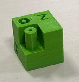
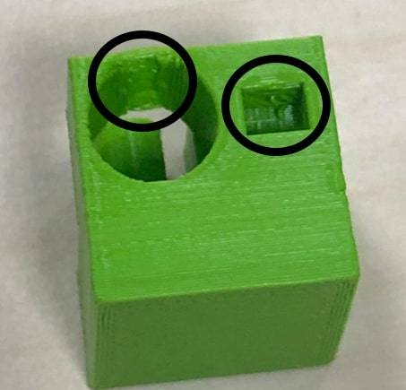
The test cube purpose was to test features like small holes, bridges, small letters and overhangs. From what I have observed the lettering was clearly visible with no issues, the hole and the cylinder were printed perfectly too. However, when it came to the bigger circular and rectangular holes, the bridging on the top was slightly dented, and pieces of the filament can be observed on the inner sides.
This was by far the hardest part in this week. It was not due to the machines deciding not to work, nor my lack of experience, nor the time limitations, its just that I didn’t have the slightest idea of what I should be designing and printing in a way that could not be created substractivly. When ever the word design came to mind, my mind went poof!.
I did a lot of research, referred to many previous projects, and spent late nights on Instagram and Pinterest (working of course!) looking up models and ideas.
Finally, I gave up on my initial idea of making something extra extraordinary, and settled for a hinge. I followed a tutorial to create a hinge in Fusion 360.
The video below shows the steps of creating said hinge.
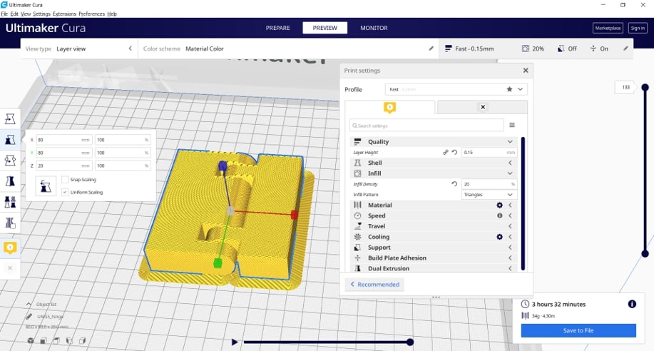
Then I exported the stl file, and opened it in Cura. The values I have selected for this design are the following:
And sliced the design. The duration for this design was 3 hours and 32 minutes.
Then printed the design using the Ultimaker 3 extended, and a PLA filament.
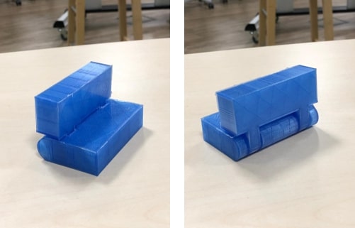
The results were pretty satisfactory! The finishing was really nice! and the hinge moved easily once the brim was removed. The hinge maximum revolution angle was just a bit over 90 degrees.
What made this design exclusive to additive manufacturing was the fact that the hinge intersecting revolving parts were printed in a single process.
For the 3D scanning part, I initially wanted to use the Sense. I have had several trials on it before, but the scanner probe wouldn’t capture the objects I was trying to scan for some reason. I am willing to try it again in a different lightning and observe the changes.
However, due to the time limitations, I wanted to move on with the task. So I installed different applications on my phone to try scanning. Most of these apps required the usage of the front camera instead of the camera on the back (I am using an iPhone X), which made scanning slightly difficult.
Then I settled with an App called Qlone, that required an AR mat to be placed underneath the object to be scanned. The mat with the black and white chalkboard pattern serves as a tracking marker for the software.
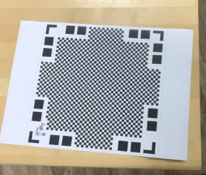
When the object is placed on the mat and the application is at use, An AR dome is placed on the center. The dome here is an indication of the capturing process. The object scanned needs to fit into the dome. The biggest limitation here is the height of the object being scanned, but that problem can be easily solved by simply printing a bigger mat.
The dome has four segments, once the scanning in a particular segment is done, then the segment turns transparent. Scanning is done by rotating around the object and turning all the segments.
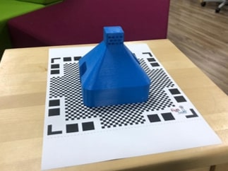
final result
I’ve also tried to scan my coffee cup using the same method, however, the results were not as accurate as my previous attempt.
One of the things I wanted to try if I had time was printing a flexible design using a rigid material. Lucky for me, we did have enough time to learn about the Zortrax 3D printer available in our Fablab.
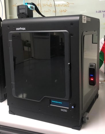
I took the chance to try using the Zortrax printer to print the flexible design I acquired from Thingiverse.
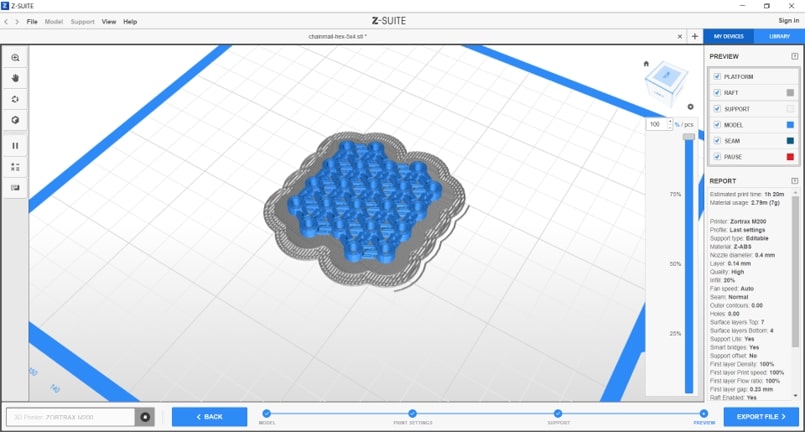
To slice the design I used the Z-suit software.
The Zortrax is mainly used for printing ABS materials hence the material is sensitive to the changes in the environment, and the Zortrax provides a great operation by shielding the design thus limiting any temperature variations due to external factors.
To start printing:
models.print.The Zortax displays the type of material, the amount of materials to be used and the print time.
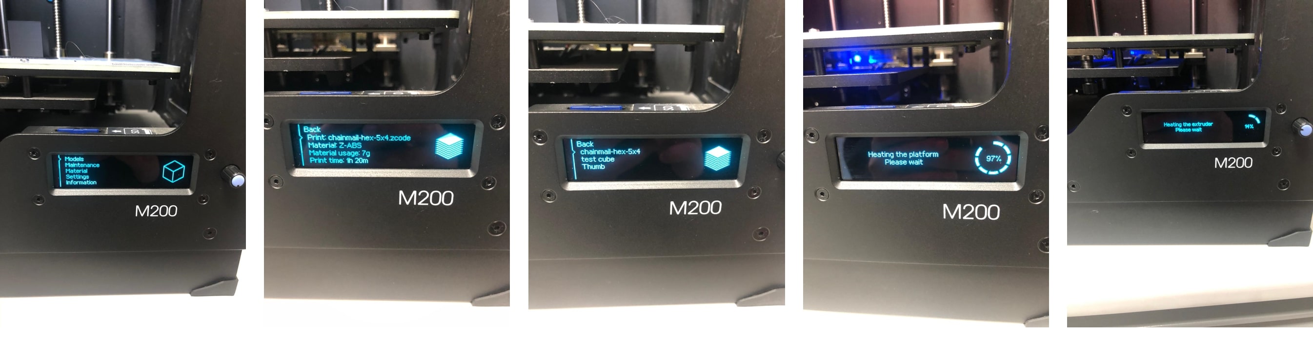
It starts by printing a raft for the print to be placed on.
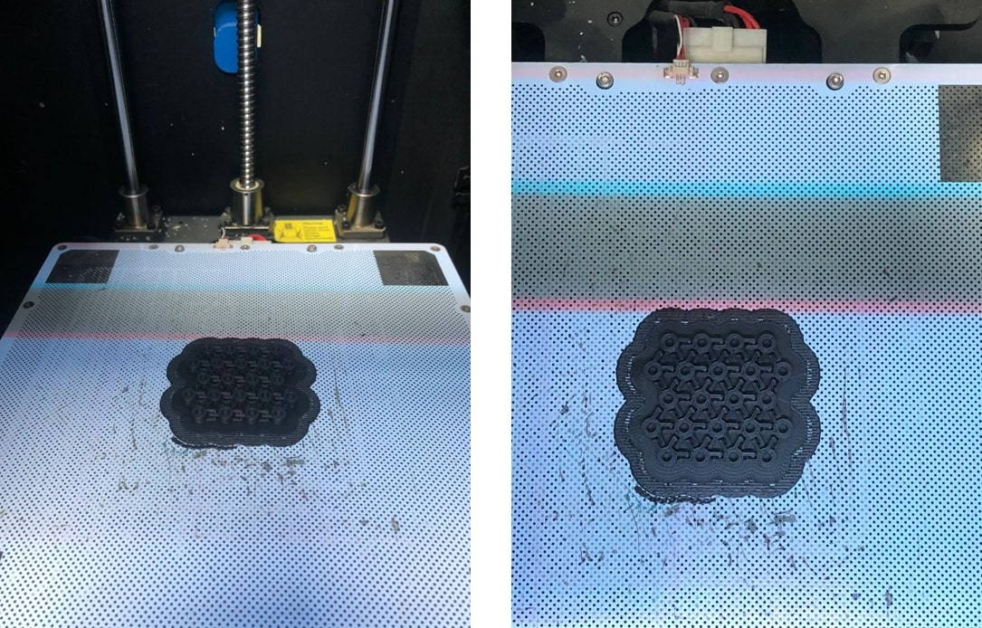
The result:
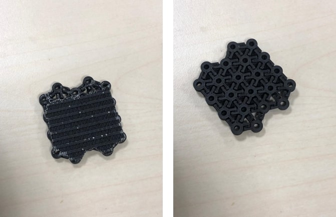
It looks great! The outer raft can be easily broken off the main design, however, the rest of the raft on the bottom layer is very hard to remove. For other designs, that maybe acceptable, but for the design at hand, the pieces need to be separated to move properly.
I tried breaking some off using my nails and a cutter, but the parts of the design broke off and I stopped.
I had another trial with this design on the Ultimaker machine using PLA. My initial plan was to print it with a skirt instead of a brim because I did not want to repeat the experience with the raft and have excess material that would need be removed in order for the design to be flexible. That was the initial idea, but while being distracted as I was using the slicer, I accidently kept the brim and printed the design.
And this is the result:
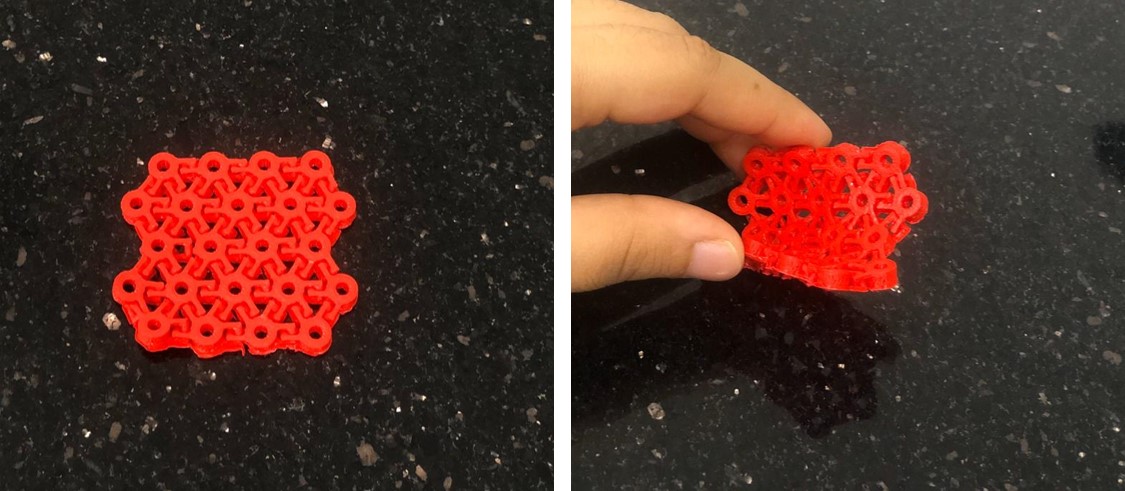
Printing the design with a brim did create a layer at the bottom of the joints. However, the layer was very thin and easily removed compared to the raft using ABS. The pictures above displays the final results after removing said layer. It turned out to be very flexible and easy to bend , but not to fold over itself, but that maybe due to the dimensions of the design (printing slightly larger would result in more flexibility, but I’ll have to experiment more with that!). ____
Despite my rough beginning, by the end of this week, I realized that I am very astonished by the creations of a 3D printer, all the possibilities!
Yet, at the same time, I realized that 3D printers are not magical machines, there are still limitations to what can be created. There were factors to be considered when both designing and printing on 3D. The clearance for example was very important factor for the hinge I created this week.
Also, at times, I was convinced that these machines had a mind of their own, refusing to cooperate in any possible way!
My files:
