The group assignment page is here
Another week working from home!
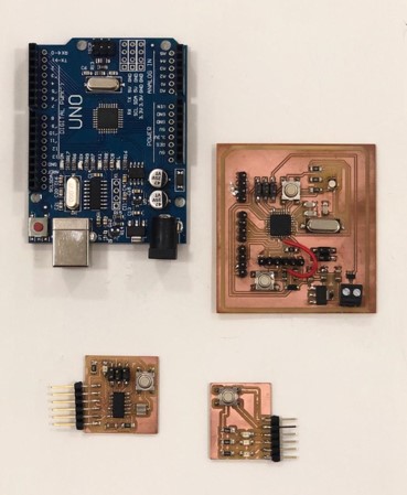
For this week, I am attempting to learn, implement and compare different communication protocols using the existing boards I have at hand, which basically are:
A commercial Arduino UNO (with the kit), an Atmega 328 board (Fabduino), an Attiny 44 board (both of which I created in the Electronics design week), and a traffic signal board (with no processor) that we produced earlier this year in the winter camp!
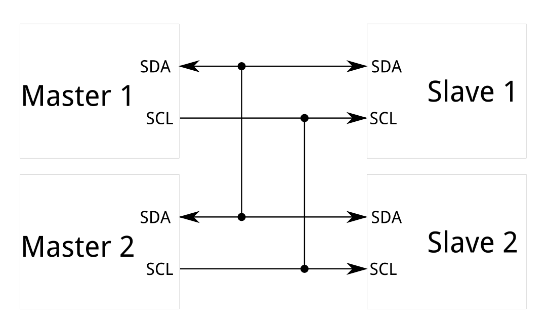
Inter intergrated circuit (I2C) is a multiple slave multiple master communication protocol.
Here’s a summary of what I know!
I2C requires two wires to establish a connection, and can support up to 1008 slave devices.
I2C bus consists of two signals: SCL (clock signal) used for alinighg the data for sampling, and SDA (data signal) used to send the data.
I2C protocol can operate at different speeds, 100 KHz, 400 KHz and 3.4 MHz. 100 KHz is the most supported speed by processors.
I2C supports multi-master, however, one master can communicate / send commands at a time (or else arbitration of the bus and clock synchronization is required).
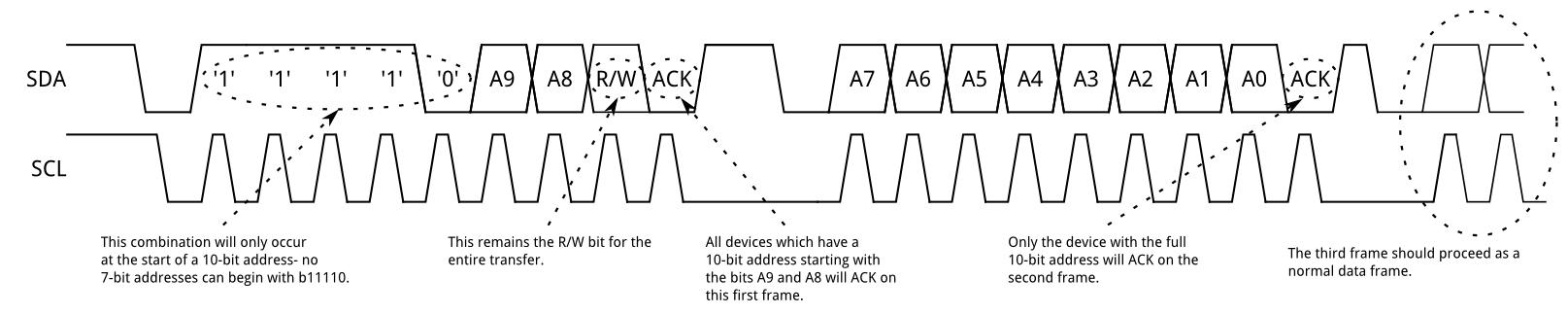
Messages in I2C protocol are divided into frames:
Initial condition : master device sets SCL high and pulls SDA low.
Address frame: 7-bit address, the address is clocked out most significant bit (MSB) first, followed by a R/W bit indicating whether this is a read (1) or write (0) operation and The 9th bit of the frame is the NACK/ACK bit.
Data frame: after sending the address frame, the master continues generating clock pulses at regular intervals, and the data is transmitted by the SDA.
Stop condition: Once all the data frames have been sent, the master will generate a stop condition. Stop conditions are defined by low to high transition on SDA after a LOW to high transition on SCL, with SCL remaining high.
I will be using the Wire.h library to communicate between the boards using I2C.
The main commads I’ll be using are the following:
Wire.begin() - Initiate the Wire library and join the I2C bus as a master or slave. leave the address empty for the master device code, and specify the address for the slave.
Wire.beginTransmission() - Begin a transmission to the I2C slave device with the given address.
Wire.write() - Writes data from a slave device in response to a request from a master, or queues bytes for transmission from a master to slave device.
Wire.endTransmission() - Ends a transmission to a slave device.
Wire.onReceive() - Registers a function to be called when a slave device receives a transmission from a master.
Wire.available() - Returns the number of bytes available for retrieval with read command, checks the availablilty of the connection between the master and the slave.
Wire.read() - Reads a byte that was transmitted from a slave device to a master.
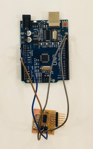
First, I tried to establish a connection between an Arduino UNO and a Fabduino (Atmega 328). The Arduino UNO I am using here has two saparate pins labelled SDA and SCL.
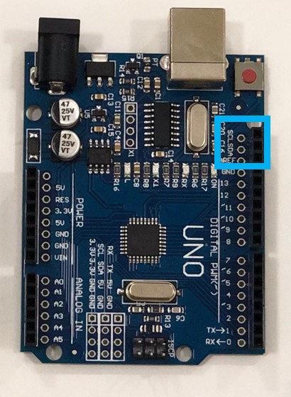
I connected the SDA, SCL, ground and power pins between the two boards, and ran the master code on the Atmega board (using an FTDI cable), and the slave code on the Arduino UNO (using the Arduino USB cable).
Note: I did not connect any external pull up resistor to the signal lines due to the arduino having its own internal pull up resistors for the SDA/SCL pins.
Here I establishing a master writer / slave reciever connection, and I am powering and reading the values through the USB cable connected to the slave Arduino. This code turns an LED ON on the Arduino when the button in the Atmega board is pressed.
Master Code
// Maha Al Hashimi
// FabLab UAE
// Fab Academy 2020


#include <Wire.h>

//initializes button
const int button = 7;
int ButtonState = 0;

void setup()
{
  Wire.begin(); // Establish an I2C connection
  pinMode(button,INPUT);//sets the button as input
  digitalWrite(button,HIGH);//Activtes pull up resistor.

}

void loop()
{
  Wire.beginTransmission(1);// start transmitting to device #1
  ButtonState = digitalRead(button);// reads button state
  Wire.write(ButtonState); //sends button state
  Wire.endTransmission();    // stop transmitting
  delay(100);
}
Slave Code
// Maha Al Hashimi
// FabLab UAE
// Fab Academy 2020

#include <Wire.h>

void setup()
{
  Wire.begin(1);                // stablish an I2C connection on slave #1
  Wire.onReceive(receiveEvent); // register event
  Serial.begin(9600);           // start serial for output
  pinMode(13,OUTPUT);// sets LED as output
}

void loop()
{
  delay(10);
}

void receiveEvent()
{
  while(Wire.available()) // while the connection is availabe
  {
    int c = Wire.read(); // recieves the button state
    Serial.println(c); // prints the button state on the serial monitor

  if (c == HIGH){ // if the button is released
    digitalWrite(13,LOW);// turn the LED off
  }
  else if (c == LOW){// if the button is pressed
    digitalWrite(13,HIGH);// turn the LED on
  }
  }
}
Demonstration video
Next was testing I2C connection on the Attiny.44 board. Since wire.h library cannot be used with attiny, I aquired a modified library TinyWire.h from here as a zip folder and added it to the libraries in Arduino.
The functions on TinyWire.h library, are similar in behaviour to the Wire.h library on Arduino.
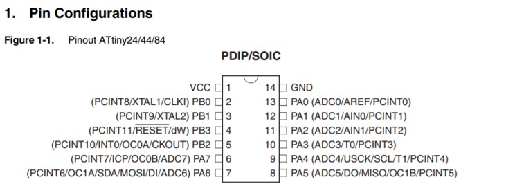
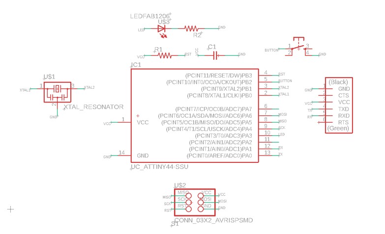
I had to check Attiny 44 datasheet for the SCL/SDA pinout, along with my own board.
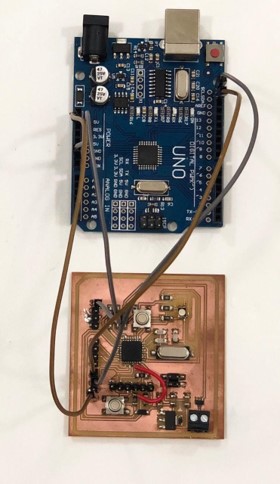
Once I figured out the connection, I wrote the master code for the Attiny and uploaded it successfuly using the FabISP created in the Electronics production week.
This code is also testing the connection by pressing a button on the master and turning ON an LED on the Slave. Here, I am powering the Attiny board using Arduino by connecting ground and VCC wires along the signal wires.
Master code
// Maha Al Hashimi
// FabLab UAE
// Fab Academy 2020

#include <TinyWire.h> // include library

const int button = 8;// set button pin
int ButtonState = 0;

void setup() {
  pinMode(button,INPUT);//sets the button as input
  digitalWrite(button,HIGH);//Activtes pull up resistor.
  pinMode(led,OUTPUT);
  TinyWire.begin();
}

void loop() {
  TinyWire.beginTransmission(1);// start transmitting to device #1
  ButtonState = digitalRead(button);// reads button state
  TinyWire.write(ButtonState); //sends button state
  TinyWire.endTransmission();    // stop transmitting
  delay(100);
}
And uploaded the slave code to the Arduino.
Slave code
// Maha Al Hashimi
// FabLab UAE
// Fab Academy 2020

#include <Wire.h>

void setup()
{
  Wire.begin(1);                // stablish an I2C connection on slave #1
  Wire.onReceive(receiveEvent); // register event
  Serial.begin(9600);           // start serial for output
  pinMode(13,OUTPUT);// sets LED as output
}

void loop()
{
  delay(10);
}

void receiveEvent()
{
  while(Wire.available()) // while the connection is availabe
  {
    int c = Wire.read(); // recieves the button state
    Serial.println(c); // prints the button state on the serial monitor

  if (c == HIGH){ // if the button is released
    digitalWrite(13,LOW);// turn the LED off
  }
  else if (c == LOW){// if the button is pressed
    digitalWrite(13,HIGH);// turn the LED on
  }
  }
}
For some reason, the connction did not work! the serial monitor did not display any signal coming from the master side and the LED did not blink! 🤔
Later, thanks to Hashim and a little reseaching, I discovered that the master functionality for Attiny devices on TinyWire.h library has a bug, as it blocks the master transmission.
I wanted to check if reversing the situation would possibly make the connection work 🤷
Again I uploaded a master code to the Arduino and a slave code to the Attiny.
This code enables the master to send a signal through the connection to blink an LED on the slave board.
Master code
// Maha Al Hashimi
// FabLab UAE
// Fab Academy 2020

#include <Wire.h>

void setup()
{
  Wire.begin(); // join i2c bus
}

void loop()
{
  Wire.beginTransmission(1); // transmit to device #1
  Wire.write("a");// sends a to turn on LED
  delay(500);
  Wire.write("b");// sends b to turn off LED
  Wire.endTransmission(); // stop transmitting
  delay(500);
}
Slave code
#include <TinyWire.h>

int LED = 3;

void setup() {
  pinMode(LED, OUTPUT); //sets LED as output
  TinyWire.begin(1); //stablish an I2C connection on slave #1
  TinyWire.onReceive( onI2CReceive );//register event
}

void loop() {
}
void onI2CReceive(){
  while(TinyWire.available()){ // while the connection is availabe
    if(TinyWire.read()=='a') // // check if the signal is a
    {
      digitalWrite(LED,HIGH); // Turn LED on
    }
    else{
      digitalWrite(LED,LOW);// Turn LED off
    }
}
}
This connection worked perfectly!
