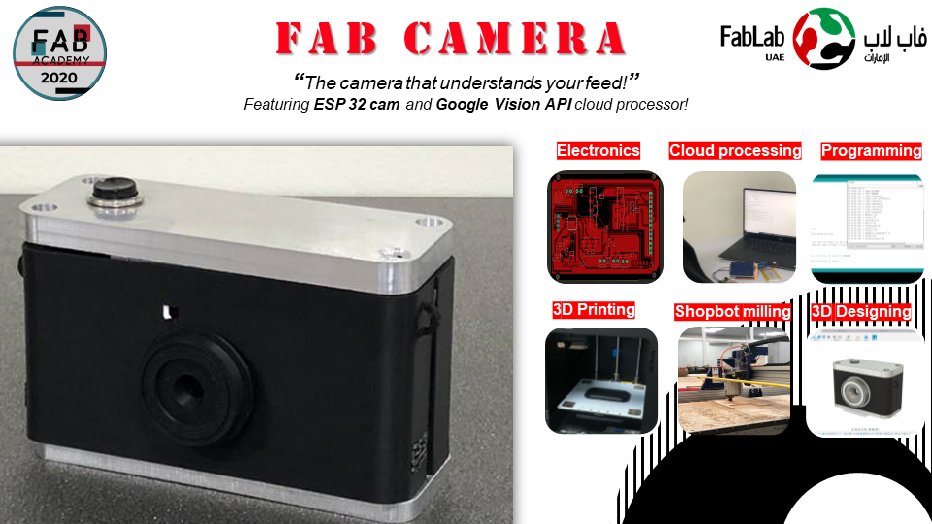
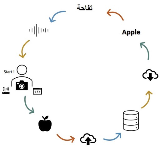
The FAB CAM is a smart tool, that creates a fun, easy experience to aid the process of learning languages. Simply, the FAB CAM allows you to take a snapshot of any object in view, process the picture, return labels of the object in English along with the corresponding Label in Arabic, and plays an audio of the label!
Connect the micro-controller (ESP-32 CAM) to your network.
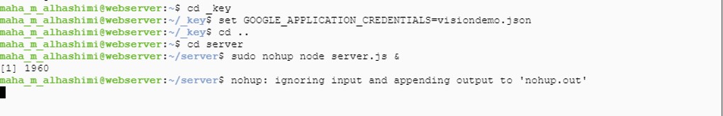
Turn on the server on the virtual machine.
Switch on the device.
point to whatever object in your surroundings.
click the button on top.
Wait for the device to return the label in English, then Arabic.
Listen to the word pronounced.
Learn and repeat (repeat from step 4)
The fab Camera is device aimed to be a fun user-friendly instant translator. The camera shaped tool is designed to inspire an easier, innovative and more enjoyable process of learning languages, featuring ESP 32 cam and Google vision cloud API processor!
There are several applications and websites that provide direct translation of images, for example apps such as google translate application on both Android and IOS devices ,and websites like the OCR online.
Additionally, image, object or face recognition is not a particularly new project in Fab academy. Our own UAE fab lab had a student: Salem Al Marri, who used facial recognition for his final project.
However, these apps and websites relay on text based images where the application scans the text and translates the content. What “The Fab Camera” is aiming to do is considered different in operation as it connects to a cloud computing server for the image recognition, and then translates based on the outcome.
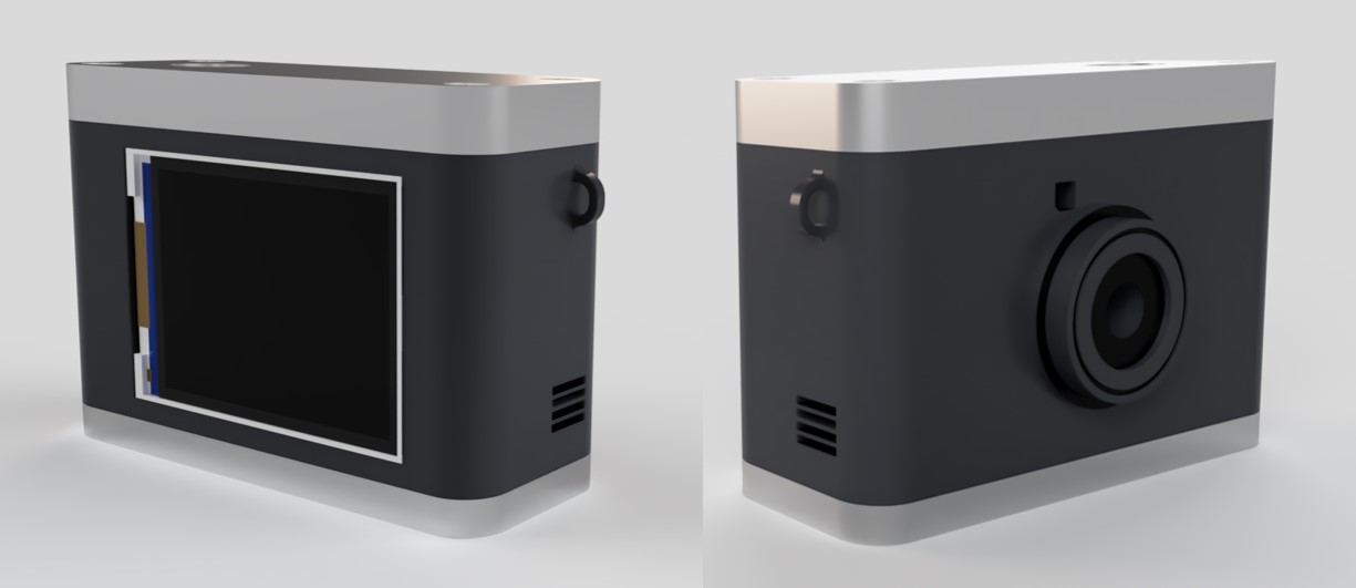
I have designed the case in the shape of a somewhat vintage camera, as well as the electronics parts for the processor, the input and output peripherals.
Z-ABS pure black for the body and the lense.
Aluminum block for the Camera top and bottom.
5 mm screws for securing the pieces together.
ESP 32 Cam.
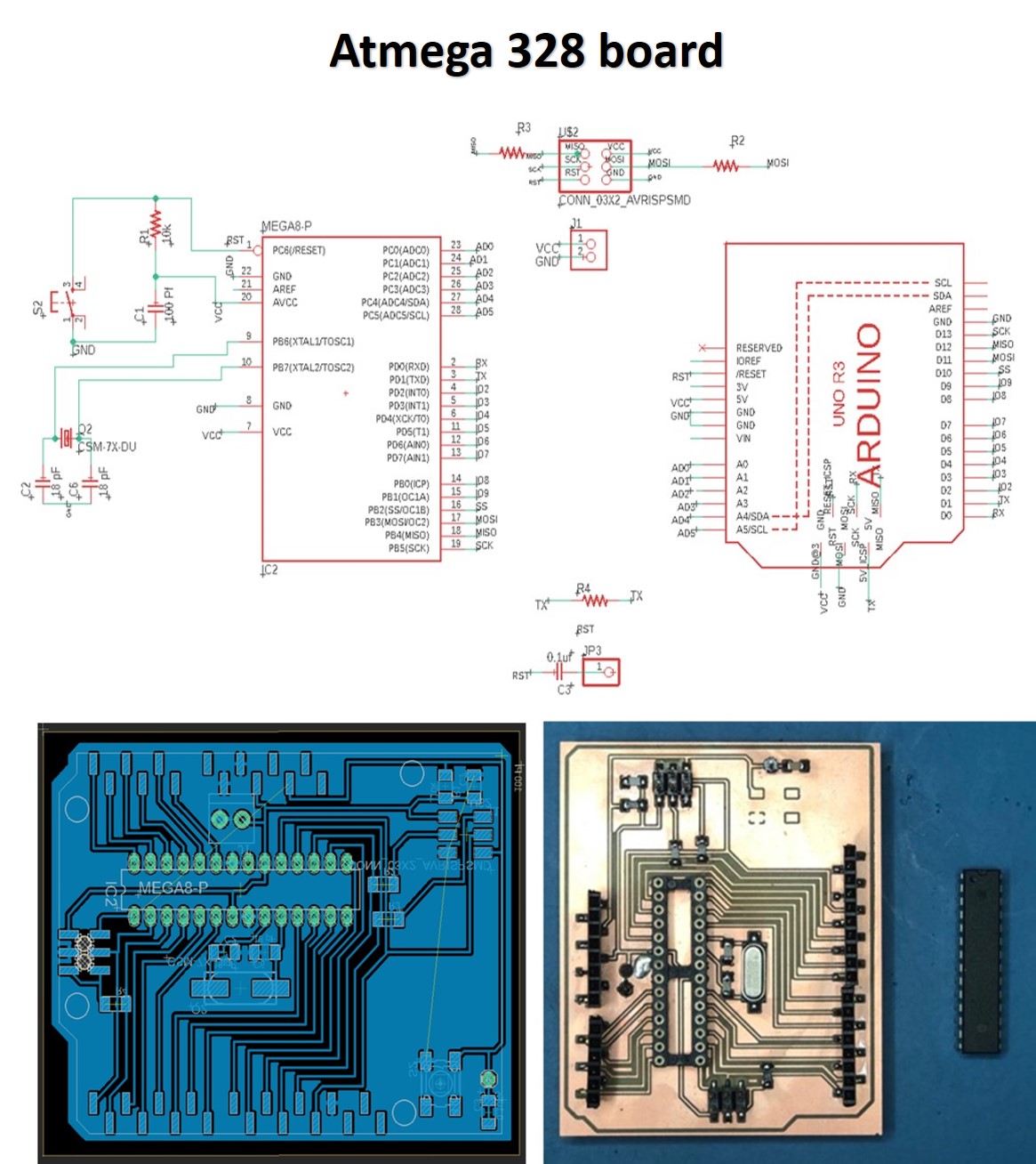
Atmega 328
ILI9431 TFT LCD screen.
Sliding Switch
SMD Button.
Capacitors and resistors.
Power and testing LEDs.
An external Button.
FTDI headers.
A lot of pinheads.
Several terminals.
Battery
Voltage step up converter.
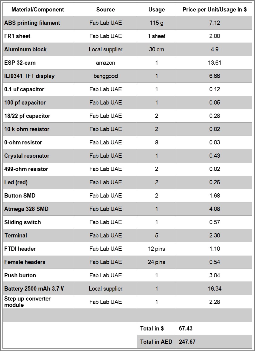
Most of the components are already available in the lab. Other elements of the projects will be purchased online or from a local electronics shop if needed. Here I excluded the prices of using the API and the virtual machine since nothing was paid while making, testing and using this project.
The case.
The electronics.
The integrated system including the setting up the API, server and VM.
I used Fusion 360 to design the 3D case. And used the Zortrax M200 3D printer to print the body and the lens.
The top and bottom parts of the design were made out of aluminum and I used the Shopbot to manufacture and mill these pieces.
For the electronics, I designed my boards in Eagle, generated the Gerber files using Flatcam and manufactured them using the SRM Roland milling machine.
As for the programming part, I used several interfaces, libraries and platforms. I used Google vision API for the object recognition in cloud processing, Node.js to create the create, test and run the server, Online Ubentu with Node.js installed in, to run the virtual machine enabling the project to become portable, and finally, Arduino IDE to run and integrate all the processes and systems together.
![]()
The Fab camera as it was intended recognizes objects using the cloud processor. The display can show a live stream of what the camera is viewing, it can capture images of several objects at a time, send them to the cloud server, return up to 10 labels for the objects recognized, and then display these labels on the screen.
However, the direct translation part unfortunately didn’t work yet. I faced some issues in extracting the labels in the way I wanted from the json objects the server returned, which are required for the translation.
The same issue is affecting the audio part as well, as I need to specify a single label to allocate the audio for it. Another issue with the library. I was able to extract the audio from the SD card, but the library I used has set a very low volume which didn’t serve it’s purpose for my project.
“The Fab camera” will be evaluated by its ability to connect to the API server, display a live video of what the camera is seeing, capture images and display the images on the screen, and return labels with a level of accuracy.
For future improvements, The fab cam should be able to correlate the labels returned to a data base of another language, and pronounce the word in several languages eventually.
This project was initially created for a personal purpose of easing the learning purpose for myself. However, while working on it, I recognized the potential of this becoming a tool that everyone can use -including students in all stages- to enjoy learning.
For the future I will be trying other cloud processing options, as what I am currently using is a partially paid service. The cloud computing server I am using is running on Google vision API, which is free for the first 1000 model/month, but is charged for any request beyond that number. Similarly, the portability of this project is achieved by having a virtual machine running that server on Google, which, unfortunately, is also a paid service. The rates for the services might be nominal, but this still creates a challenge for mass production and distribution.
For my final project, I worked on two versions that were similar yet different. The reasons why I did so, was the limited time we had after the lockdown as we were rushing everything, and the compatibility of the screen I used with the ESP 32 cam, which eventually the right screen arrived :) !
I will be briefing on both versions as I worked hard on both of them.
For the case I used Fusion 360 to design the Camera case. The camera comes in 6 parts to easily insert the other components/electronics inside.
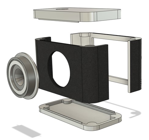
I made sure to create alignment pieces to fit the top and bottom parts to the body of the camera.
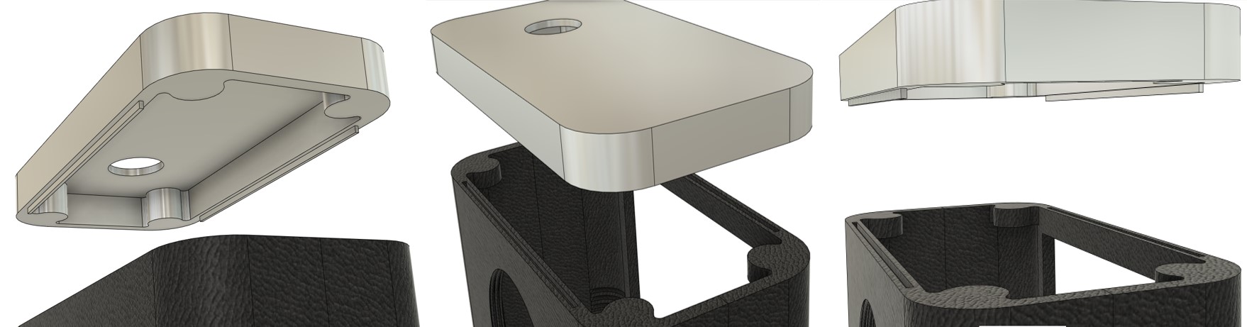
The final design of the camera:
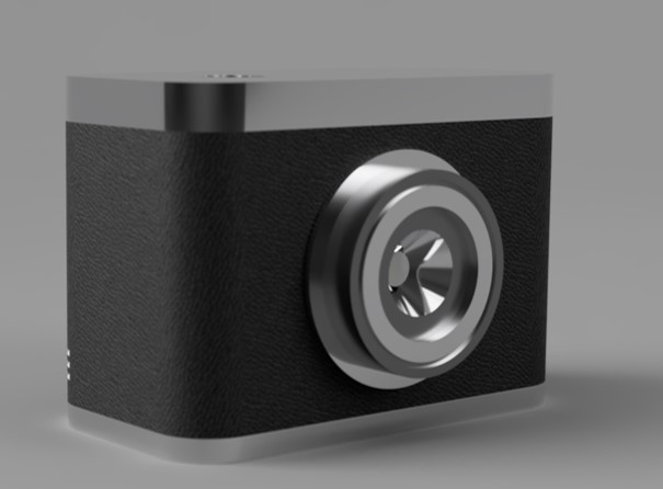
Camera V1 by maha.m.alhashimi on Sketchfab
I printed the 3D pieces in true black Z-ABS, using the M200 Zortrax printer.
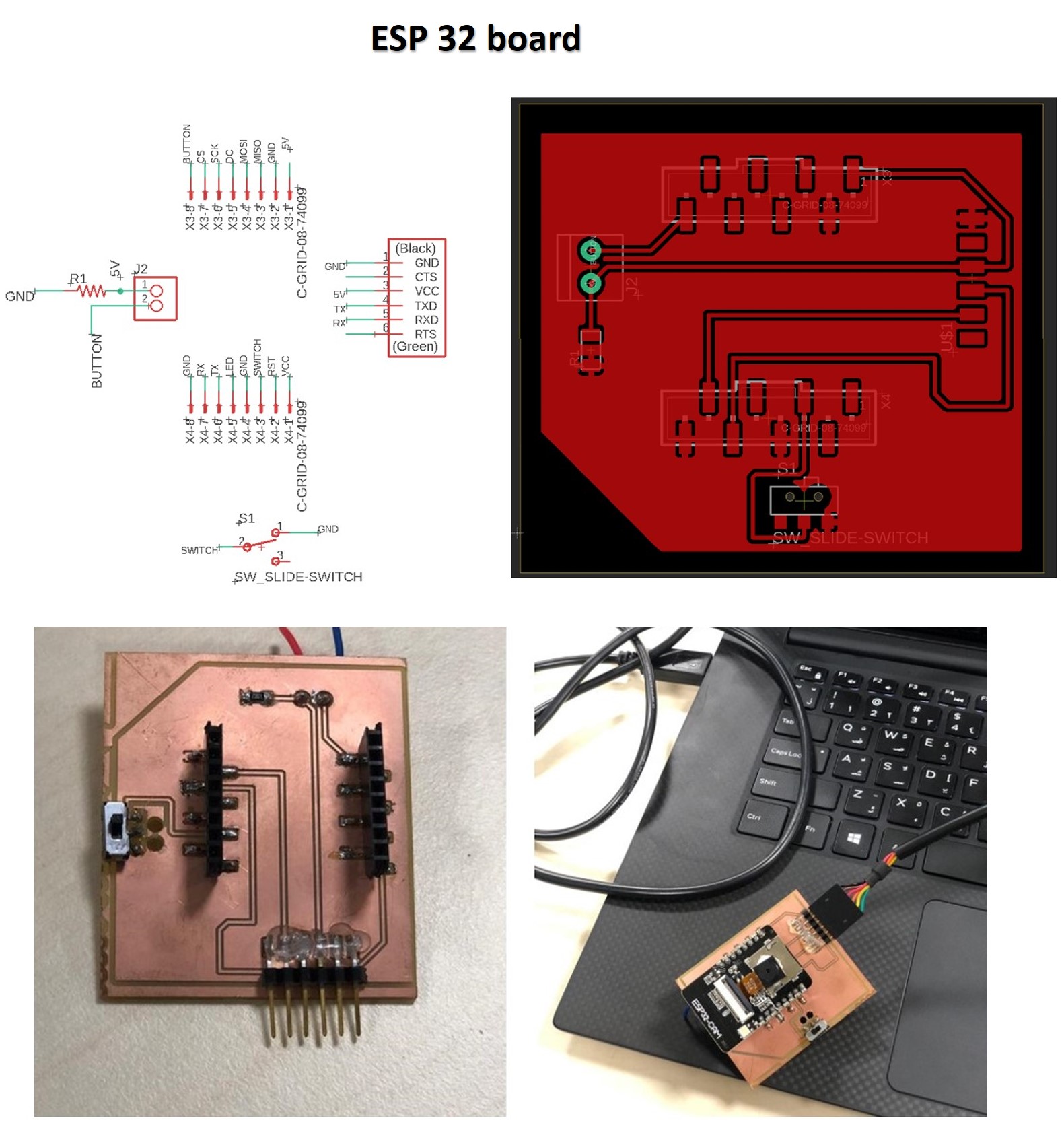
For the electronics I used the ESP 32 cam board I designed in my input devices week, and the Atmega 328 board, with the screen mount I designed in my output devices week.
I designed both boards in Eagle, generated the g-codes for the boards using flatcam as explained in my electroncis design week.
The ESP 32 cam is programmed to stream a live output of what the camera is capturing at the moment. When the button is clicked however, the camera takes a still image and sends it to the server, Which then is connected to the API and does the processing required. The API setup documentation can be found here.
For the API, first the virtual machine should be started, and the IP generated is copied to the ESP32 code to for the microcontroller to connect to the server, making sure that the server is turned on the VM.
The following code is the server using google API:
var fs = require('file-system');
const http = require('http');
const server = http.createServer();
const filePath = './resources/test.jpeg';

server.on('request', (request, response)=>{
    if(request.method == 'POST' && request.url === "/imageUpdate"){

        var ImageFile = fs.createWriteStream(filePath, {encoding: 'utf8'});
        request.on('data', function(data){
            ImageFile.write(data);
        });

        request.on('end',async function(){
            ImageFile.end();
            const labels = await labelAPI();
            response.writeHead(200, {'Content-Type' : 'application/json'});
            response.end(JSON.stringify(labels));
        });


    }else{
        console.log("error");
        response.writeHead(405, {'Content-Type' : 'text/plain'});
        response.end();
    }
});

async function labelAPI() {
  // Imports the Google Cloud client library
  const vision = require('@google-cloud/vision');

  // Creates a client
  const client = new vision.ImageAnnotatorClient();

  // Performs label detection on the image file
  const [result] = await client.labelDetection(filePath);
  const labels = result.labelAnnotations;
  var o = [];
  labels.forEach(label => {
    o.push({description: label.description, score: label.score});
  });
  return o;
}

const port = 8888;
server.listen(port)
console.log(`Listening at ${port}`)
The server then returns the labels in the form of a json document, which then is de-serialized, and then we extract the labels as json objects and display it on the screen.
To execute this code I needed several libraries to be installed:
SPI.h - This library is for synchronous serial data connection by microcontrollers.
HTTPClient.h - HttpClient is a library to make it easier to interact with web servers from Arduino.
ArduinoJson.h - A C++ JSON library for Arduino and IoT (Internet Of Things).
To upload the code to the ESP 32, I had to add the code bits to the same camera example page of the ESP 32 cam. This example is found by selecting the ESP 32 Wrover board from the Tools > Board > Arduino ESP 32 menu, then heading to files > examples >ESP 32 > Camera > CameraWebServer.
The code:
// Maha Al Hashimi
// Fab Academy 2020, Fab Lab UAE.

// Include all the libraries required.

#include "esp_camera.h"
#define CAMERA_MODEL_AI_THINKER
#include "camera_pins.h"
#include <SPI.h>
#include <WiFi.h>
#include <HTTPClient.h>
#include <ArduinoJson.h>

const char* ssid = "******";
const char* password = "*****";
const unsigned long timeout = 1000; // 10 seconds

const int buttonPin = 4;    // the number of the pushbutton pin
int buttonState;
int lastButtonState = LOW;
unsigned long lastDebounceTime = 0;  // the last time the output pin was toggled
unsigned long debounceDelay = 50;    // the debounce time; increase if the output flickers
bool isNormalMode = true;


void setup() {
  Serial.begin(115200);
  delay(1000);

  Serial.println();
  pinMode(buttonPin, INPUT);

  //Serial.println("INIT DISPLAY");
  //Serial.println("INIT CAMERA");
  camera_config_t config;
  config.ledc_channel = LEDC_CHANNEL_0;
  config.ledc_timer = LEDC_TIMER_0;
  config.pin_d0 = Y2_GPIO_NUM;
  config.pin_d1 = Y3_GPIO_NUM;
  config.pin_d2 = Y4_GPIO_NUM;
  config.pin_d3 = Y5_GPIO_NUM;
  config.pin_d4 = Y6_GPIO_NUM;
  config.pin_d5 = Y7_GPIO_NUM;
  config.pin_d6 = Y8_GPIO_NUM;
  config.pin_d7 = Y9_GPIO_NUM;
  config.pin_xclk = XCLK_GPIO_NUM;
  config.pin_pclk = PCLK_GPIO_NUM;
  config.pin_vsync = VSYNC_GPIO_NUM;
  config.pin_href = HREF_GPIO_NUM;
  config.pin_sscb_sda = SIOD_GPIO_NUM;
  config.pin_sscb_scl = SIOC_GPIO_NUM;
  config.pin_pwdn = PWDN_GPIO_NUM;
  config.pin_reset = RESET_GPIO_NUM;
  config.xclk_freq_hz = 10000000; // original is 20M change it to 10Mb
  config.pixel_format = PIXFORMAT_JPEG;
  //init with high specs to pre-allocate larger buffers
  if(psramFound()){
    config.frame_size = FRAMESIZE_QVGA; // 320x240
    config.jpeg_quality = 10;
    config.fb_count = 2;
  } else {
    config.frame_size = FRAMESIZE_SVGA;
    config.jpeg_quality = 12;
    config.fb_count = 1;
  }


  // initializes the camera
  esp_err_t err = esp_camera_init(&config);
  if (err != ESP_OK) {
    Serial.printf("Camera init failed with error 0x%x", err);
    return;
  }
}

// connects to the WIFI available , if it doesn't work check the WIFI credentials.
bool wifiConnect(){
  unsigned long startingTime = millis();
  WiFi.begin(ssid, password);

  while(WiFi.status() != WL_CONNECTED){
    delay(500);
    if((millis() - startingTime) > timeout){
      return false;
    }
  }
  return true;
}

//initializes the button event for image capturing

void buttonEvent(){
  int reading = digitalRead(buttonPin);
  if (reading != lastButtonState) {
    lastDebounceTime = millis();
  }

  if ((millis() - lastDebounceTime) > debounceDelay) {
    if (reading != buttonState) {
      buttonState = reading;

      if (buttonState == HIGH) {
        isNormalMode = !isNormalMode;

        //Additional Code
        if(!isNormalMode)
          sendingImage();
        //
      }
    }
  }
  lastButtonState = reading;
}


camera_fb_t* capture(){
  camera_fb_t *fb = NULL;
  esp_err_t res = ESP_OK;
  fb = esp_camera_fb_get();
  return fb;
}


void showingImage(){
  camera_fb_t *fb = capture();
  if(!fb || fb->format != PIXFORMAT_JPEG){
    Serial.println("Camera capture failed");
    esp_camera_fb_return(fb);
    return;
  }else{
    esp_camera_fb_return(fb);
  }
}

// get the json document from the server

void parsingResult(String response){
  DynamicJsonDocument doc(1024);
  deserializeJson(doc, response);
  JsonArray array = doc.as<JsonArray>();
  int yPos = 4;
  for(JsonVariant v : array){
    JsonObject object = v.as<JsonObject>();
    String description = object["description"];
    Serial.println(description);
}

void postingImage(camera_fb_t *fb){
  HTTPClient client;
  client.begin("http://**:**:**:***:8888/imageUpdate"); // add the IP address of the remote server here.
  client.addHeader("Content-Type", "image/jpeg");
  int httpResponseCode = client.POST(fb->buf, fb->len);
  if(httpResponseCode == 200){
    String response = client.getString();
    parsingResult(response);
  }else{
    //Error
    Serial.println("check the server");

  }

  client.end();
  WiFi.disconnect();
}

void sendingImage(){
  camera_fb_t *fb = capture();
  if(!fb || fb->format != PIXFORMAT_JPEG){
    Serial.println("Camera capture failed");
    esp_camera_fb_return(fb);
    return;
  }else{
    //Serial.println("wifi connecting");

    if(wifiConnect()){
      //Serial.println("wifi connected");
      postingImage(fb);
    }else{
      Serial.println("check wifi credentials");
    }
    esp_camera_fb_return(fb);
  }
}

void loop() {
  buttonEvent();

  if(isNormalMode)
    showingImage();

}
In the previous code, I sent the labels I got from the json document on the serial monitor. This is to then read it on the Atmega board, and display a bit map picture corresponding to label sent.
Here I used the original code example of the screen that displays bitmap pictures. I altered the code so that the serial connection is checked first. if it is available then it reads the set of strings sent by the ESP. The json objects returned from the server are a set of strings of various labels for the same objects with different scores, to display a bit map photo I needed to trim this set to display the first label only (which is the label with the highest score).
Atmega code:
// Maha Al Hashimi
// Fab Academy, Fab Lab UAE 2020.

#include <SPI.h>            // f.k. for Arduino-1.5.2
#include <SD.h>             // Use the official SD library on hardware pins

#include <Adafruit_GFX.h>   // Hardware-specific library
#include <MCUFRIEND_kbv.h>
MCUFRIEND_kbv tft;
#include <Fonts/FreeSans9pt7b.h>
#include <Fonts/FreeSans12pt7b.h>
#include <Fonts/FreeSerif12pt7b.h>
#include <FreeDefaultFonts.h>
#define BLACK   0x0000
#define RED     0xF800
#define GREEN   0x07E0
#define WHITE   0xFFFF
#define GREY    0x8410

#endif
#define NAMEMATCH ""        // "" matches any name
#define PALETTEDEPTH   0     // do not support Palette modes


char namebuf[32] = "/";   //BMP files in root directory
//char namebuf[32] = "/bitmaps/";  //BMP directory e.g. files in /bitmaps/*.bmp

File root;
int pathlen;
String description; //set "description" as string to store the labels coming on the serial monitor.
int last = 0;

void setup()
{

  //setting the screen
    uint16_t ID;
    Serial.begin(115200);
    Serial.print("Show BMP files on TFT with ID:0x");
    ID = tft.readID();
    Serial.println(ID, HEX);
    if (ID == 0x0D3D3) ID = 0x9481;
    tft.begin(ID);
    tft.fillScreen(0x001F);
    tft.setTextColor(0xFFFF, 0x0000);
     tft.setRotation(1);
    bool good = SD.begin(SD_CS);
    if (!good) {
        Serial.print(F("cannot start SD"));
        while (1);
    }
    root = SD.open(namebuf);
    pathlen = strlen(namebuf);
}

void loop()
{
  tft.fillScreen(0);
  if (Serial.available() > 0) { // checks if the serial is available
    description = Serial.readString();// reads the set of strings on the serial monitor
    Serial.println("the image label is:");
    int label_length = description.length(); // checks the length of the strings
    //Serial.println(label_length);
    for (int i=0 ; i < label_length ; i++) // this following loop breaks the set of strings on the serial monitor to one string only, so it is easy to identify and display a picture according to.
    {
      if (description.charAt(i) == '\n')
      {
        //Serial.println("hi");
        last = i;
        break;
      }
    }
    //Serial.println(last);
    description.remove(last); // removes the last string before the label needed
    description.trim();
    Serial.println(description);
    //last = 0;
    if (description == "Hand") // checks if the label is "hand", then displays a bitmap photo of hand and writes the label on the screeen
    {
      showBMP("hand.bpm", 10, 10);
      showmsgXY(0, 0, 2, NULL, "hand");

    }
    else if(description == "Table")
    {
      showBMP("table.bpm", 10, 10);
      showmsgXY(0, 0, 2, NULL, "table");
    }
}


}

#define BMPIMAGEOFFSET 54
#define BUFFPIXEL      20
uint16_t read16(File& f) {
    uint16_t result;         // read little-endian
    f.read((uint8_t*)&result, sizeof(result));
    return result;
}

uint32_t read32(File& f) {
    uint32_t result;
    f.read((uint8_t*)&result, sizeof(result));
    return result;
}

uint8_t showBMP(char *nm, int x, int y)
{
    File bmpFile;
    int bmpWidth, bmpHeight;    // W+H in pixels
    uint8_t bmpDepth;           // Bit depth (currently must be 24, 16, 8, 4, 1)
    uint32_t bmpImageoffset;    // Start of image data in file
    uint32_t rowSize;           // Not always = bmpWidth; may have padding
    uint8_t sdbuffer[3 * BUFFPIXEL];    // pixel in buffer (R+G+B per pixel)
    uint16_t lcdbuffer[(1 << PALETTEDEPTH) + BUFFPIXEL], *palette = NULL;
    uint8_t bitmask, bitshift;
    boolean flip = true;        // BMP is stored bottom-to-top
    int w, h, row, col, lcdbufsiz = (1 << PALETTEDEPTH) + BUFFPIXEL, buffidx;
    uint32_t pos;               // seek position
    boolean is565 = false;      //

    uint16_t bmpID;
    uint16_t n;                 // blocks read
    uint8_t ret;

    if ((x >= tft.width()) || (y >= tft.height()))
        return 1;               // off screen

    bmpFile = SD.open(nm);      // Parse BMP header
    bmpID = read16(bmpFile);    // BMP signature
    (void) read32(bmpFile);     // Read & ignore file size
    (void) read32(bmpFile);     // Read & ignore creator bytes
    bmpImageoffset = read32(bmpFile);       // Start of image data
    (void) read32(bmpFile);     // Read & ignore DIB header size
    bmpWidth = read32(bmpFile);
    bmpHeight = read32(bmpFile);
    n = read16(bmpFile);        // # planes -- must be '1'
    bmpDepth = read16(bmpFile); // bits per pixel
    pos = read32(bmpFile);      // format
    if (bmpID != 0x4D42) ret = 2; // bad ID
    else if (n != 1) ret = 3;   // too many planes
    else if (pos != 0 && pos != 3) ret = 4; // format: 0 = uncompressed, 3 = 565
    else if (bmpDepth < 16 && bmpDepth > PALETTEDEPTH) ret = 5; // palette
    else {
        bool first = true;
        is565 = (pos == 3);               // ?already in 16-bit format
        // BMP rows are padded (if needed) to 4-byte boundary
        rowSize = (bmpWidth * bmpDepth / 8 + 3) & ~3;
        if (bmpHeight < 0) {              // If negative, image is in top-down order.
            bmpHeight = -bmpHeight;
            flip = false;
        }

        w = bmpWidth;
        h = bmpHeight;
        if ((x + w) >= tft.width())       // Crop area to be loaded
            w = tft.width() - x;
        if ((y + h) >= tft.height())      //
            h = tft.height() - y;

        if (bmpDepth <= PALETTEDEPTH) {   // these modes have separate palette
            //bmpFile.seek(BMPIMAGEOFFSET); //palette is always @ 54
            bmpFile.seek(bmpImageoffset - (4<<bmpDepth)); //54 for regular, diff for colorsimportant
            bitmask = 0xFF;
            if (bmpDepth < 8)
                bitmask >>= bmpDepth;
            bitshift = 8 - bmpDepth;
            n = 1 << bmpDepth;
            lcdbufsiz -= n;
            palette = lcdbuffer + lcdbufsiz;
            for (col = 0; col < n; col++) {
                pos = read32(bmpFile);    //map palette to 5-6-5
                palette[col] = ((pos & 0x0000F8) >> 3) | ((pos & 0x00FC00) >> 5) | ((pos & 0xF80000) >> 8);
            }
        }

        // Set TFT address window to clipped image bounds
        tft.setAddrWindow(x, y, x + w - 1, y + h - 1);
        for (row = 0; row < h; row++) { // For each scanline...
            // Seek to start of scan line.  It might seem labor-
            // intensive to be doing this on every line, but this
            // method covers a lot of gritty details like cropping
            // and scanline padding.  Also, the seek only takes
            // place if the file position actually needs to change
            // (avoids a lot of cluster math in SD library).
            uint8_t r, g, b, *sdptr;
            int lcdidx, lcdleft;
            if (flip)   // Bitmap is stored bottom-to-top order (normal BMP)
                pos = bmpImageoffset + (bmpHeight - 1 - row) * rowSize;
            else        // Bitmap is stored top-to-bottom
                pos = bmpImageoffset + row * rowSize;
            if (bmpFile.position() != pos) { // Need seek?
                bmpFile.seek(pos);
                buffidx = sizeof(sdbuffer); // Force buffer reload
            }

            for (col = 0; col < w; ) {  //pixels in row
                lcdleft = w - col;
                if (lcdleft > lcdbufsiz) lcdleft = lcdbufsiz;
                for (lcdidx = 0; lcdidx < lcdleft; lcdidx++) { // buffer at a time
                    uint16_t color;
                    // Time to read more pixel data?
                    if (buffidx >= sizeof(sdbuffer)) { // Indeed
                        bmpFile.read(sdbuffer, sizeof(sdbuffer));
                        buffidx = 0; // Set index to beginning
                        r = 0;
                    }
                    switch (bmpDepth) {          // Convert pixel from BMP to TFT format
                        case 24:
                            b = sdbuffer[buffidx++];
                            g = sdbuffer[buffidx++];
                            r = sdbuffer[buffidx++];
                            color = tft.color565(r, g, b);
                            break;
                        case 16:
                            b = sdbuffer[buffidx++];
                            r = sdbuffer[buffidx++];
                            if (is565)
                                color = (r << 8) | (b);
                            else
                                color = (r << 9) | ((b & 0xE0) << 1) | (b & 0x1F);
                            break;
                        case 1:
                        case 4:
                        case 8:
                            if (r == 0)
                                b = sdbuffer[buffidx++], r = 8;
                            color = palette[(b >> bitshift) & bitmask];
                            r -= bmpDepth;
                            b <<= bmpDepth;
                            break;
                    }
                    lcdbuffer[lcdidx] = color;

                }
                tft.pushColors(lcdbuffer, lcdidx, first);
                first = false;
                col += lcdidx;
            }           // end cols
        }               // end rows
        tft.setAddrWindow(0, 0, tft.width() - 1, tft.height() - 1); //restore full screen
        ret = 0;        // good render
    }
    bmpFile.close();
    return (ret);
}

void showmsgXY(int x, int y, int sz, const GFXfont *f, const char *msg)
{
    int16_t x1, y1;
    uint16_t wid, ht;
    tft.drawFastHLine(0, y, tft.width(), WHITE);
    tft.setFont(f);
    tft.setCursor(x, y);
    tft.setTextColor(BLACK);
    tft.setTextSize(sz);
    tft.print(msg);
    delay(1000);
}
The ESP 32 cam board and the Atmega board are joined through a serial connection to communicate between the two microcontrollers. They are also joined by a ground and VCC connection to derive power from the battery.
The battery I used was 3.5 volts which was not enough for my project (I used a step up for it to reach 5 V), but was good because it was available at the time and it was thin enough to fit in the case.
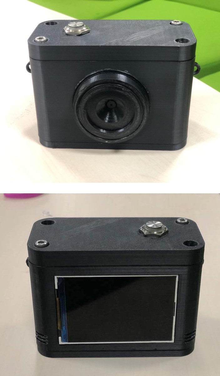
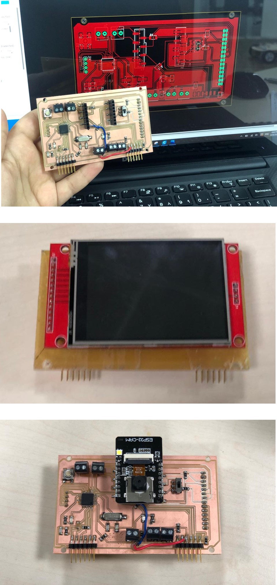
The first version of the Fab Cam:
This camera was good, but it didn’t fulfil my aim for this project. I needed to see what the camera was viewing at all times and check the what is captured an sent to the server. So this wasn’t enough, however, the this was what I had available at the moment.
I re-designed the case in Fusin 360. I went for the camera design again in the same 6 parts, but the case turned out much thinner, with a smaller lens. I also added a hole for the flash in the ESP 32 board to utilize it.
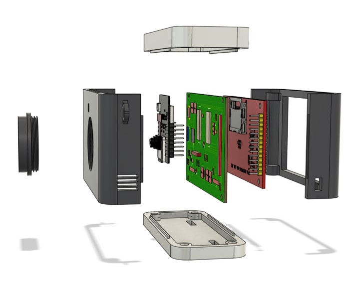
The final design of the camera:
Fab Cam version 2 by maha.m.alhashimi on Sketchfab
Similarly to the first version, I printed the body of the case in Z-ABS using the M200 Zortrax printer.
However, for the top and bottom parts of the camera, I used the Shopbot to fabricate the pieces (which was a new experience indeed! but proved to be very hard).
I generated the G-codes for the top and bottom parts using the CAM/manufacture feature in Fusion 360. The general process of using the feature is described in my molding and casting week.
All the operations are described in my top part and bottom part setup sheets. A summary of the feeds and Speeds I used:
Spindle speed: 9500 rpm.
Ramp spindle speed: 9500 rpm.
Cutting feed rate: 500 mm/min.
Ramp feed rate: 333.333 mm/min.
Plunge feed rate: 200 mm/min.
This required the usage 6 mm and 3 mm Aluminum mill bits, machining lubricant, and much needed patience. The aluminum comes in a large block (3 meters), so we trimmed it to the required size, then we taped the aluminum piece to the Shopbot bed (on a wood sheet) using strong double sided adhesive tape.
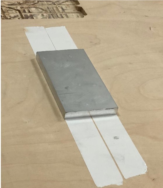
We set the origin points the height for the milling using the same steps mentioned in my Computer controlled machining week. And selected the g-code files generated by Fusion 360 to start milling.
We milled the aluminum block while keeping a close (but safe!) distance as it required constant lubrication for the mill bit. The noise was strident, and there was a lot of metal swarf.
WARNING: The video contains loud noise, listen at your own risk.
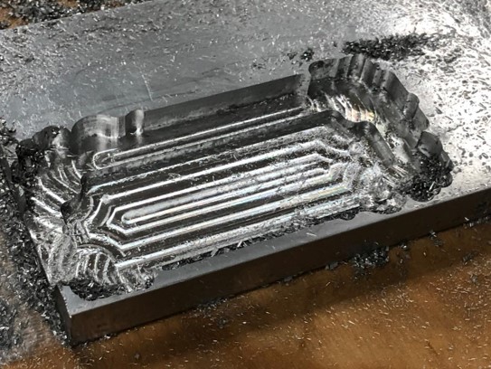
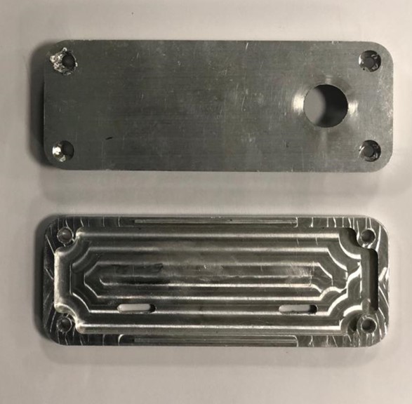
The aluminum pieces required double sided milling, thus we created “pockets” in the wood sheet with the same dimensions as the pieces I’ve milled earlier to secure the metal pieces while milling the other side.
The process tool about 2 days (a day for each part), as we struggled to work with the aluminum a bit. But, thanks to Hashim we got a beautiful result at the end.
I designed a single board in eagle that has both the ESP 32 cam mount, and the Atmega board to communicate to the speaker and the SD card reader on the screen shield. I also wanted to reduce the number of wires connecting my board to the screen, so I designed the board so that the screen is mounted directly on the back using headers.
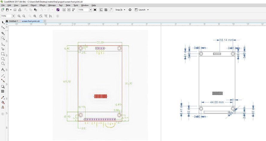
To do so, I searched for the screen shield to directly use it in Eagle for the exact measurements and locations of the pins. However, I didn’t find the ready shield, but instead an image with the real life measurements of the shield.
I tried using Coral draw to trace shield outlines, unfortunately, the original image was in a bad quality and the trace didn’t give the result I required, so I outlined the lines and measured the distances manually. Then I saved it as a DXF. To ensure that the shield is exactly the right size, I printed the image and placed the screen on top to compare! Surprisingly, the dimensions turned nearly equal.
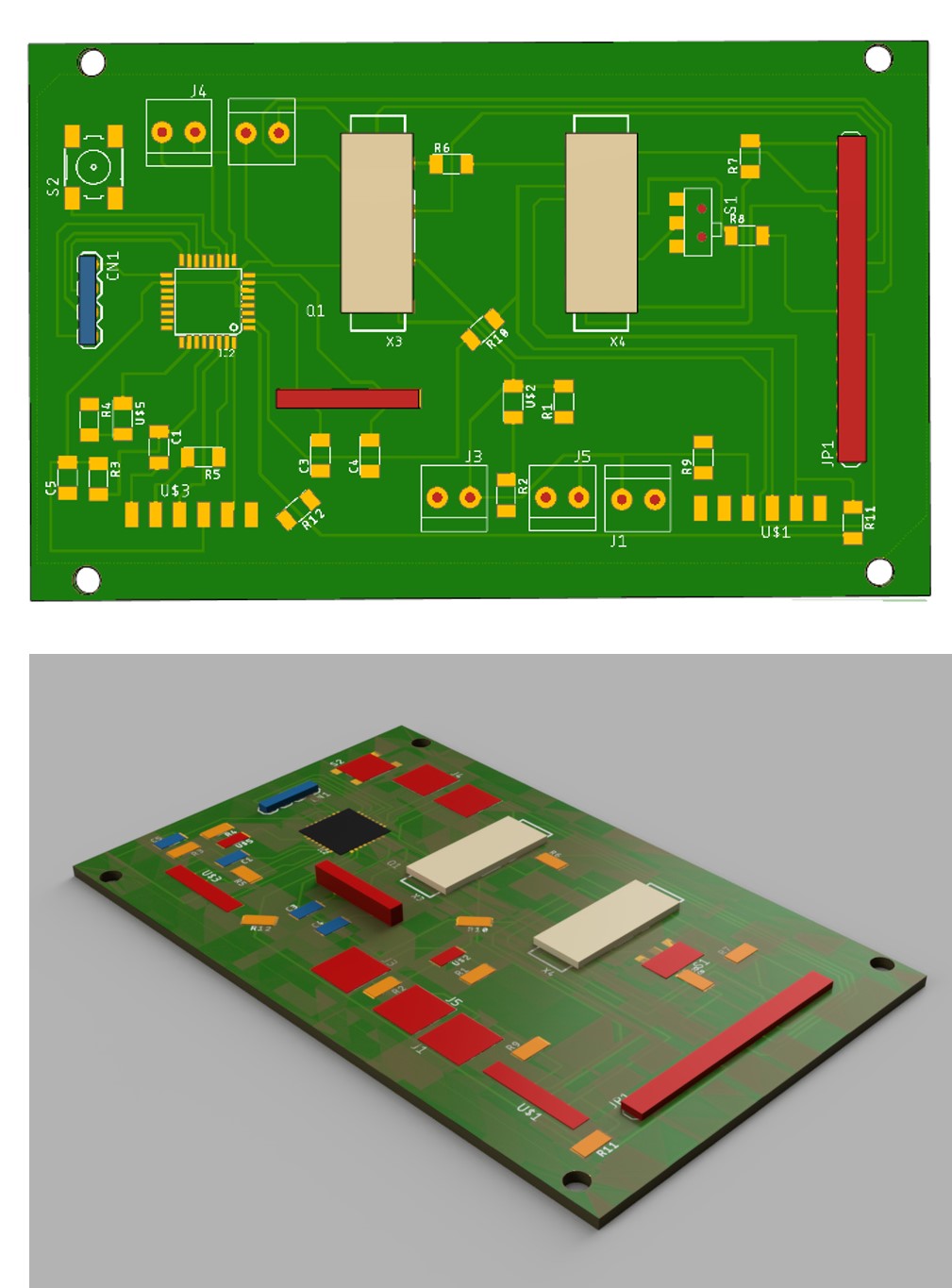
My board for the second version of the Fab Camera is the following:
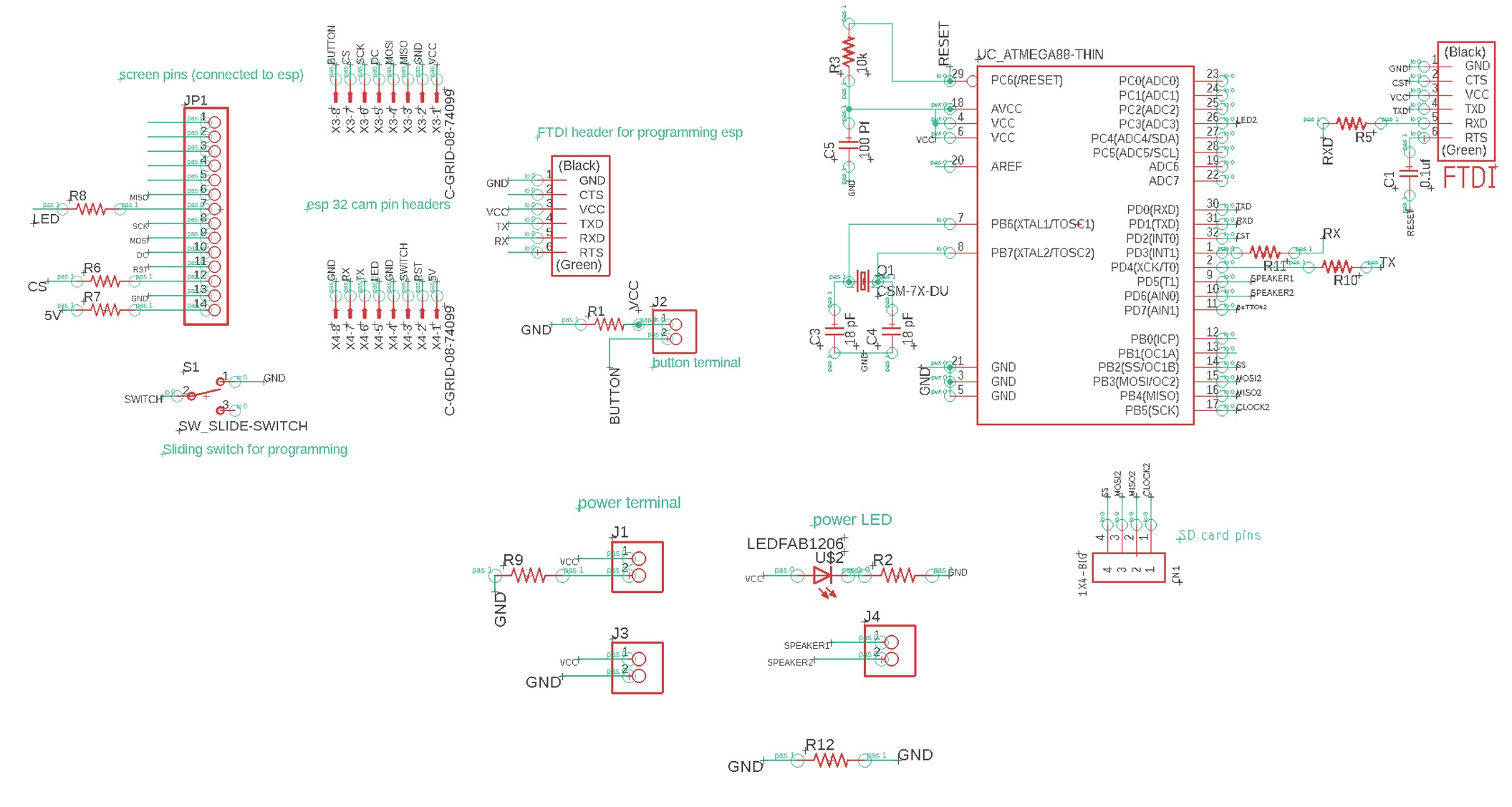
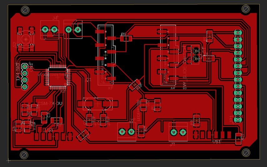
Note : The board might have needed some surgical interference 😅
To ease the designing process, I exported my electronics boards from eagle to Fusion 360 to be able to align it properly using the cam feature in Eagle.
For the second version, I am using the same server with the virtual machine explained in the first version. And the same ESP 32 code as the first version, only with added libraries to use the ILI9431 TFT screen, and display a live stream of what the camera is capturing.
The libraries I used are the following:
SPI.h - This library is for synchronous serial data connection by microcontrollers.
TJpg_Decoder.h - This library allows the rendering of JPeg images taken by the ESP 32 camera, and display the results onto a TFT display.
TFT_eSPI.h - An Arduino IDE compatible graphics and fonts library for 32 bit processors, with optimized performance for STM32, ESP8266 and ESP32 types.
HTTPClient.h - HttpClient is a library to make it easier to interact with web servers from Arduino.
ArduinoJson.h - A C++ JSON library for Arduino and IoT (Internet Of Things).
#include "esp_camera.h"
#define CAMERA_MODEL_AI_THINKER
#include "camera_pins.h"
#include <TJpg_Decoder.h>
#include <SPI.h>
#include <TFT_eSPI.h>
#include <WiFi.h>
#include <HTTPClient.h>
#include <ArduinoJson.h>

#define GFXFF 1
#define FSB9 &FreeSerifBold9pt7b

TFT_eSPI tft = TFT_eSPI();

const char* ssid = "*****";
const char* password = "******";
const unsigned long timeout = 1000; // 10 seconds

const int buttonPin = 4;    // the number of the pushbutton pin
int buttonState;
int lastButtonState = LOW;
unsigned long lastDebounceTime = 0;  // the last time the output pin was toggled
unsigned long debounceDelay = 50;    // the debounce time; increase if the output flickers
bool isNormalMode = true;
String term;
//String term;


bool tft_output(int16_t x, int16_t y, uint16_t w, uint16_t h, uint16_t* bitmap)
{
   // Stop further decoding as image is running off bottom of screen
  if ( y >= tft.height() ) return 0;

  // This function will clip the image block rendering automatically at the TFT boundaries
  tft.pushImage(x, y, w, h, bitmap);

  // This might work instead if you adapt the sketch to use the Adafruit_GFX library
  // tft.drawRGBBitmap(x, y, bitmap, w, h);

  // Return 1 to decode next block
  return 1;
}

void setup() {
  Serial.begin(115200);
  delay(1000);

  Serial.println();
  pinMode(buttonPin, INPUT);

  //Serial.println("INIT DISPLAY");
  tft.begin();
  tft.setRotation(3);
  tft.setTextColor(0xFFFF, 0x0000);
  tft.fillScreen(TFT_YELLOW);
  tft.setFreeFont(FSB9);

  TJpgDec.setJpgScale(1);
  TJpgDec.setSwapBytes(true);
  TJpgDec.setCallback(tft_output);

  //Serial.println("INIT CAMERA");
  camera_config_t config;
  config.ledc_channel = LEDC_CHANNEL_0;
  config.ledc_timer = LEDC_TIMER_0;
  config.pin_d0 = Y2_GPIO_NUM;
  config.pin_d1 = Y3_GPIO_NUM;
  config.pin_d2 = Y4_GPIO_NUM;
  config.pin_d3 = Y5_GPIO_NUM;
  config.pin_d4 = Y6_GPIO_NUM;
  config.pin_d5 = Y7_GPIO_NUM;
  config.pin_d6 = Y8_GPIO_NUM;
  config.pin_d7 = Y9_GPIO_NUM;
  config.pin_xclk = XCLK_GPIO_NUM;
  config.pin_pclk = PCLK_GPIO_NUM;
  config.pin_vsync = VSYNC_GPIO_NUM;
  config.pin_href = HREF_GPIO_NUM;
  config.pin_sscb_sda = SIOD_GPIO_NUM;
  config.pin_sscb_scl = SIOC_GPIO_NUM;
  config.pin_pwdn = PWDN_GPIO_NUM;
  config.pin_reset = RESET_GPIO_NUM;
  config.xclk_freq_hz = 10000000;
  config.pixel_format = PIXFORMAT_JPEG;
  //init with high specs to pre-allocate larger buffers
  if(psramFound()){
    config.frame_size = FRAMESIZE_QVGA; // 320x240
    config.jpeg_quality = 10;
    config.fb_count = 2;
  } else {
    config.frame_size = FRAMESIZE_SVGA;
    config.jpeg_quality = 12;
    config.fb_count = 1;
  }


  // camera init
  esp_err_t err = esp_camera_init(&config);
  if (err != ESP_OK) {
    Serial.printf("Camera init failed with error 0x%x", err);
    return;
  }
}

bool wifiConnect(){
  unsigned long startingTime = millis();
  WiFi.begin(ssid, password);

  while(WiFi.status() != WL_CONNECTED){
    delay(500);
    if((millis() - startingTime) > timeout){
      return false;
    }
  }
  return true;
}

void buttonEvent(){
  int reading = digitalRead(buttonPin);
  if (reading != lastButtonState) {
    lastDebounceTime = millis();
  }

  if ((millis() - lastDebounceTime) > debounceDelay) {
    if (reading != buttonState) {
      buttonState = reading;

      if (buttonState == HIGH) {
        isNormalMode = !isNormalMode;

        //Additional Code
        if(!isNormalMode)
          sendingImage();
        //
      }
    }
  }
  lastButtonState = reading;
}

camera_fb_t* capture(){
  camera_fb_t *fb = NULL;
  esp_err_t res = ESP_OK;
  fb = esp_camera_fb_get();
  return fb;
}

void showingImage(){
  camera_fb_t *fb = capture();
  if(!fb || fb->format != PIXFORMAT_JPEG){
    Serial.println("Camera capture failed");
    esp_camera_fb_return(fb);
    return;
  }else{
    TJpgDec.drawJpg(0,0,(const uint8_t*)fb->buf, fb->len);
    esp_camera_fb_return(fb);
  }
}


void parsingResult(String response){
  DynamicJsonDocument doc(1024);
  deserializeJson(doc, response);
  JsonArray array = doc.as<JsonArray>();
  int yPos = 4;
  for(JsonVariant v : array){
    JsonObject object = v.as<JsonObject>();
    String description = object["description"];
    Serial.println(description);
    term = Serial.readString();
    //Serial.println("the image label is:");
    int label_length = term.length();
    //Serial.println(label_length);
    for (int i=0 ; i < label_length ; i++)
    {
      if (term.charAt(i) == '\n')
      {
        //Serial.println("hi");
        last = i;
        break;
      }
    }
    //Serial.println(last);
    term.remove(last);
    term.trim();
    String define = Serial.readString(term);

    //tft.drawString(label, 8, yPos, GFXFF);
    tft.drawString(define, 8, yPos, GFXFF);
    yPos += 16;
  }
}

void postingImage(camera_fb_t *fb){
  HTTPClient client;
  client.begin("http://**.**.**.**:8888/imageUpdate");// add IP address of VM or server.
  client.addHeader("Content-Type", "image/jpeg");
  int httpResponseCode = client.POST(fb->buf, fb->len);
  if(httpResponseCode == 200){
    String response = client.getString();
    parsingResult(response);
  }else{
    //Error
    tft.drawString("Check Your Server!!!", 8, 4, GFXFF);
    Serial.println("check the server");

  }

  client.end();
  WiFi.disconnect();
}

void sendingImage(){
  camera_fb_t *fb = capture();
  if(!fb || fb->format != PIXFORMAT_JPEG){
    Serial.println("Camera capture failed");
    esp_camera_fb_return(fb);
    return;
  }else{
    TJpgDec.drawJpg(0,0,(const uint8_t*)fb->buf, fb->len);

    tft.drawString("Wifi Connecting!", 8, 4, GFXFF);
    //Serial.println("wifi connecting");

    if(wifiConnect()){
      //tft.drawString("Wifi Connected!", 8, 4, GFXFF);
      TJpgDec.drawJpg(0,0,(const uint8_t*)fb->buf, fb->len);
      //Serial.println("wifi connected");
      postingImage(fb);
    }else{
      tft.drawString("Check Wifi credential!", 8, 4, GFXFF);
      Serial.println("check wifi credentials");
    }
    esp_camera_fb_return(fb);
  }
}

void loop() {
  buttonEvent();

  if(isNormalMode)
    showingImage();

}
The second version of Fab Cam:
Note: Sometimes the server can not recognize objects accurately if the object is far away or is not very generic.
I have faced a lot of challenges with this project:
Th design. Different materials react differently to external factors (ex. temperature). I had to learn this through trials and errors. I have 3D printed the design a couple of times (a lot!), using different materials (Nylon, ABS, PLA, Z-ABS). Each time, I found out that measurements differ which presented issues in alignments and didn’t provide a good finishing for the case. Also, the printers got stubborn, and challenged me every time I tried working with it.
Issues with the ESP 32 cam, crashing and getting a bunch of errors. Some are addressed and fixed in my input devices week.
The compatibility of the screen with the ESP 32. To display what the Esp 32 cam is capturing live, it is required to use a very specific screen (ILI9431). Unfortunately, the screen was not available in my country in any local vendor or a local online shop, thus I had to wait until it arrived (hence the first version of fab cam). While waiting, I tried several screens with different drivers which didn’t work :(
Google API server. As motioned in my details page, cloud computing is not free. While the user gets about 300 dollars to use on the account per registration, there are minimal fees for using the server.
Mobility. The server now runs on a virtual machine set google cloud, the usage of the virtual machine is not free, but charged per hour (see details page.). This has two options which are either the VM can run for as long as we want (increasing the cost), or we can shut the VM, then re-start it when the FAB Cam is used. The second option (which seems better), generates a different IP address each time the VM is re-started, which means that the code for the ESP 32 has to be updated every time.
I would love to create a third version of the Fab Camera where the translation and the audio part work properly.
Also, I would explore other cloud computing options and API services to work on the ESP 32. One significant issue I had with the API I am curranty using is the fact that it is a paid service. Google vision API is free for the 1000 model/month but is charged for any request beyond that number. Similarly, the portability of this project is achieved by having a virtual machine running that server on Google, which, unfortunately, is also a paid service. The rates for the services might be nominal, but this still creates a challenge for mass production and distribution.
Here’s some behind the scenes footage of my various failures that eventually lead to a success!
I am thankful for this opportunity offered by Hamdan bin Rashid Al Maktoum foundation, and Fab Lab UAE to take on this wonderful journey to learn, create and grow. And for Neil for creating and presenting this course.
I am also truly grateful for the constant support of our instructor Hashim throughout the course of Fab Academy, and especially while working on the final project, for my colleagues in this cycle for sharing their skills and experiences and aiding me throughout, and for Fab Lab UAE engineers for assisting us kindly.
Thank you all, I couldn’t have finished this project without you!
Fab Cam V1 - ESP 32 schematic
Fab Cam V1 - ESP 32 Board
Fab Cam V1 - Atmega 328 schematic
Fab Cam V1 - Atmega 328 Board
Fab Cam V2 - Final schematic
Fab Cam V2 - Final Board
