5. Electronics production
This week Assignments!
Group assignment: characterize the design rules for your PCB production process!
Individual assignment
make an in-circuit programmer by milling and stuffing the PCB, test it, then optionally try other PCB processes.
Machine
The Machine that exists in Techworks Amman is:
-“ROLAND SRM-20”
Features
- Loadable Workpiece Size: 8” x 6” x 2.8” Table Size: 9.14” x 6.17” Max Tool Size: 1/4” or 6mm.
Spindle Speed: 3000-7000 rpm.
-
Tools: Milling bit 0,8 (1/32”), Milling bit 0,4 mm (1/64”).
-

Softwares
Mods is a project lead by Prof. Neil Gershenfeld in the CBA that allows one connect modules, i.e. devices that do very specific tasks, using a friendly web interface. It allows people to use a web-browser to connect devices and do computation. By doing so it can be used to build modular machines that do a variety of tasks.
Materials
- copper tape ” FR-4”
Safety
 .
.
Group assignment
For the Group assignment we have to learn about the - ROLAND SRM-20 and how it works, in order to cut and mill the defult board then solder the components to be used as a ISP for the final project or so!
Step 1 : We downloded the png test files:

Step 2 : open Mods then follow the steps as shown in the pic to import the png file to get the rml file in order to start the mill processes.


Then you upload the png file to get the rml ready with following the steps below:


After uploded the png file you should change the offset amount to 1 to get plus Materials cut.
-

-
We used Milling bit 0,8 (1/32”) for the Interior.
- Milling bit 0,4 mm (1/64”) for the traces.

I will explain how to import the rml file to the machine in the individual assignment:
Here is the cutting operation:
-  -
-  -
- 
individual assignment
Files
We have to Make an in-circuit programmer by milling and stuffing the PCB, test it, then optionally try other PCB processes.


I downloaded the png files to and did the same process in the group Assignments:
Milling machine setting and milling the PCB by the press on the button in the top corner of the machine. In computer open the Vpanel for SRM-20 program controller for setting to initialise the mill bit for cut and trace operation. FR1 PCB sticks with double-sided paper tape as shown in the figure below and placed on to the top of the wooden basement of SRM-20 milling machine. Move the head to origine position, click X/Y-set origin point button, move z-axis close to table, lower the bit, click Z-setting The Vpanel is also shows in the figure below which allow setting to initialise the XYZ position zero before trace and cut operation. Followed by click cut-delete the existing file and add the rml file for milling. Mill bit for trace and outline are different. After milling the trace clean the milling dest using vacuum cleaner and change the mill bit using the align key by carefully hold the mill bit in between two figures without dropping it. Then press output button for start milling. Keep in mind little up after Z zero positioning before output press for starting the milling. See the figures below for more detailed visualisation.
Working with Mods :
First : open mods from the link above.
Second step :righlt click and choose program then choose from the list ‘Open server program’ then choose ‘SRM 20 - png PCP’ .

Third step : from the interface that shown below click on ‘ select png files ‘ and choose the png file.

4th Step :
1- After selecting the png file ‘interior’ it is going to apper on the screen as an input.
2- From ‘set PCB defaults’ choose the secound option ‘ mill outline (1/32)’.
3- Then from ‘ mill raster 2D’ choose ‘calculate’.

for the traces i followed the same for the interior .
- 

Work with SRM-20
1- PCP preparations :

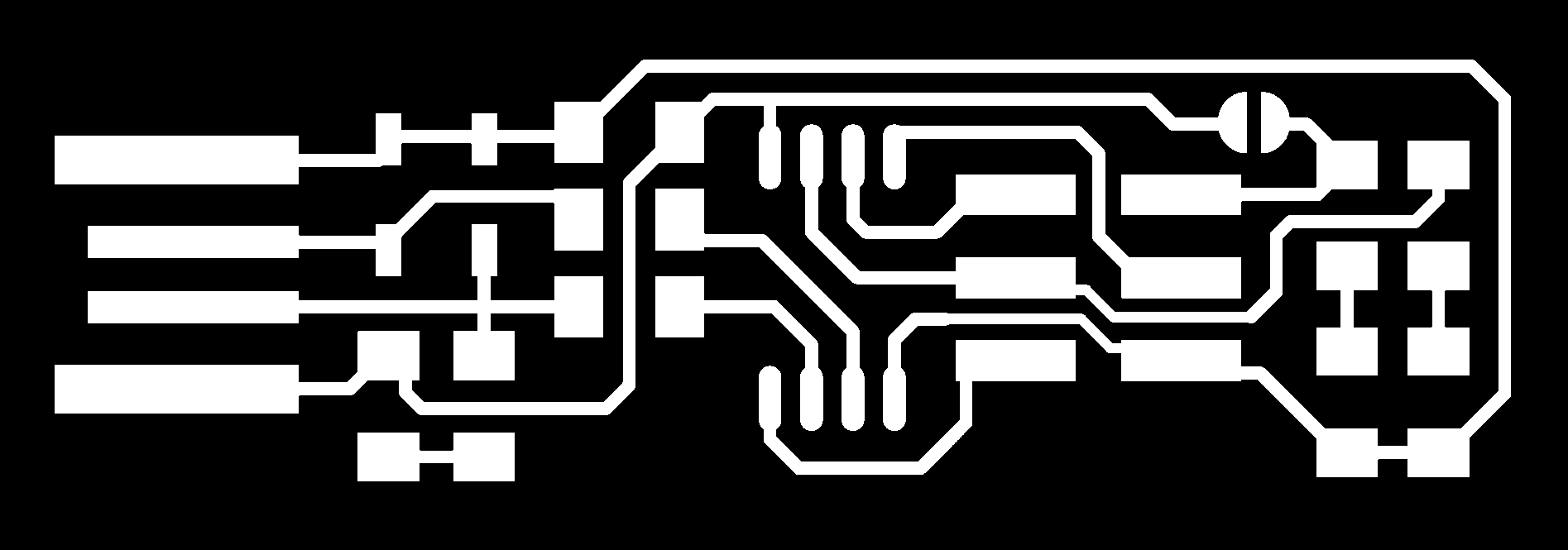
making an in-circuit programmer
For the individual assignment, I followed documentation by Brian Documentation. PCB fabrication, I downloaded Traces 1000 dpi png file and Outline Cut 1000 dpi png file. Convert the rml file based on the mod program explained in the group assignment. I used flat mill bit 0.4 mm (tool diameter) and 0.1 mm (cut depth for trace). For cutting the outline, I used 1 mm mill bit, and 0.6 mm cut depth per one mill and step down to 3 to 4. PCB mill bit images and trace and cut PCB are shown in the figure below.


After i finished milling the PCP i went to the soldering process:
The components i used for ISP:
- 
  - ATtiny45 x1

  - 1kΩ resistors x2

  - 499Ω resistors x2

  - 49Ω resistors x2

  - 3v zener diodes x2

  - red LED x1

  - green LED x1

  - 100nF capacitor x1

  - 2x3 pin header x1
The work space :
- 
Soldering gun :
- 
Soldering
programming The board


to program the ISP you have to connect it with a programmed ISP:
Step 1: Enter the command “make flash” then if it works
Step 2 : Enter the command “make fuse” after that to make sure your ISP is actually programmed
Step 3 : enter the command “lsusb” and tha will list USB devices.
If you see a “Multiple Vendors USBtiny” device that means it worked.
IMG_9414 from Omar Rawashdeh on Vimeo.
