Fifth assignment
Date
19 Feb 2020
I have a basic knowledge of Electronics. I always wanted to dive deeper into this field. This assignment gave me the chance to do that first by making my own Printed Circuit Board (PCB).
So excited !
The process of making an in-circuit programmer :
1) Milling the PCB.
2) Soldering the components.
3) programming.
I followed this tutorial step by step to Build the ISP.
Milling the PCB.
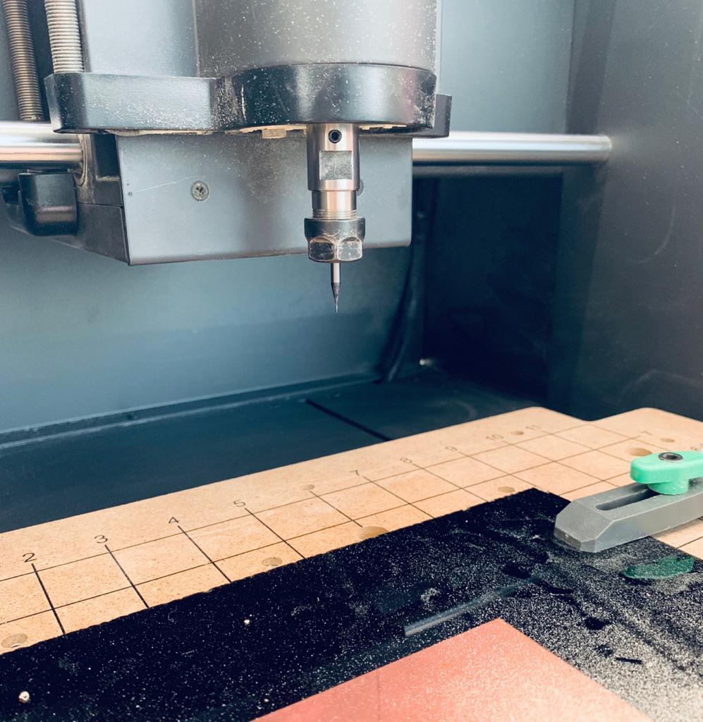
The CNC Milling machine that I used for this task is called “ Carvey''. I used to work with STEPCRAFT CNC before but I found Carvey at the talents lab. I like it more because it has a fully-enclosed area that keeps the place clean from the dust and reduces the noise.
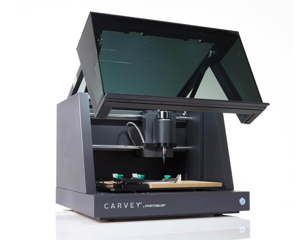
Preparing the Carvey machine :
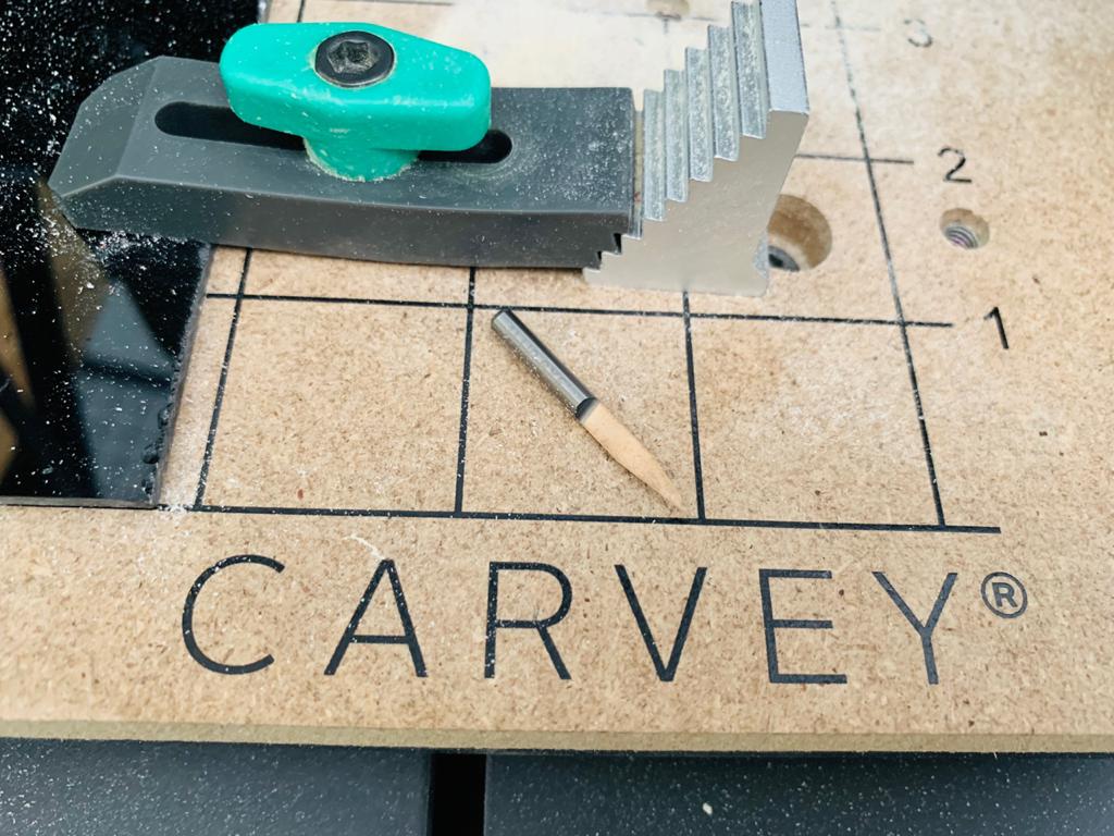
I positioned the copper board at the corner then I put the double-sided tape to secure the material to the work area. The most important step during the preparation was using the smart clamps to make sure the material will not move. I put a suitable bit for engraving.
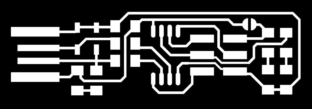
I used the FabTinyISP traces and the board outline as a PNG format.

The Easel software designed by Inventables. It is the online user interface for the CNC machine. It allows you to carve any project that you designed. You need to create an account if you don't have one.
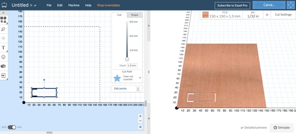
This is the easel interface. Hmmm, It looks simple and easy. Let’s explore the tools and features!
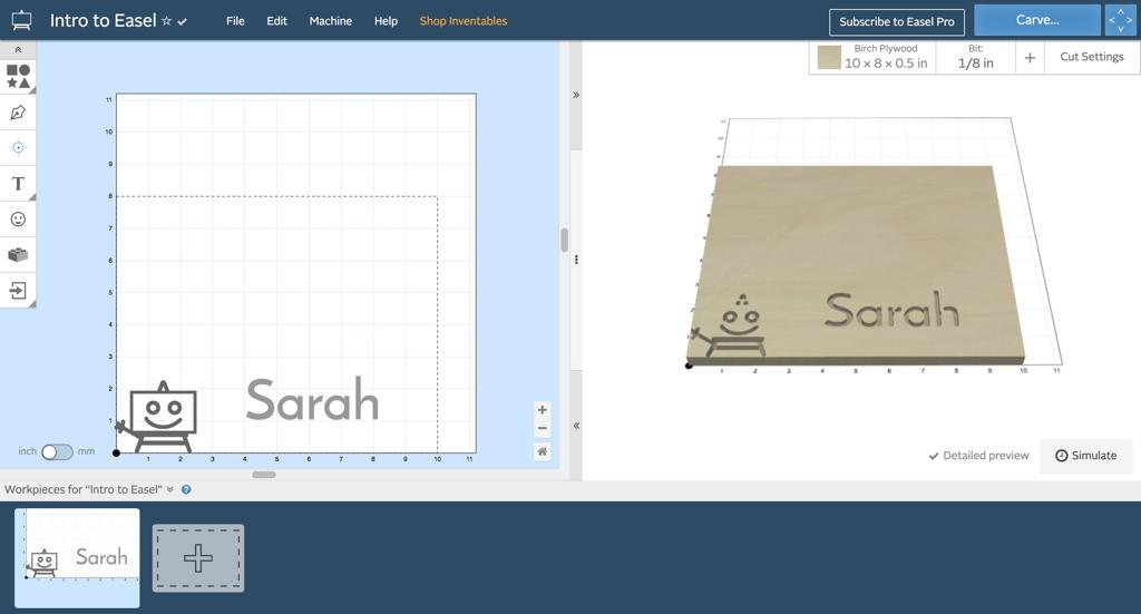
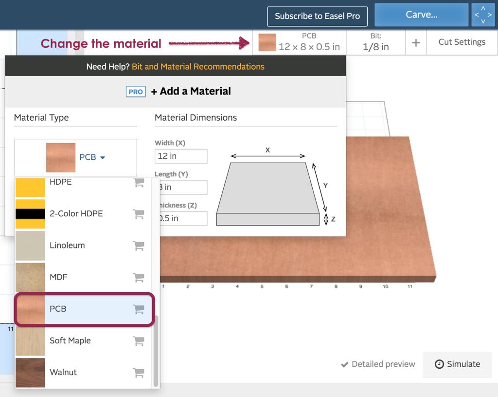
First, I changed the material type to PCB and I determined the dimensions of the material.
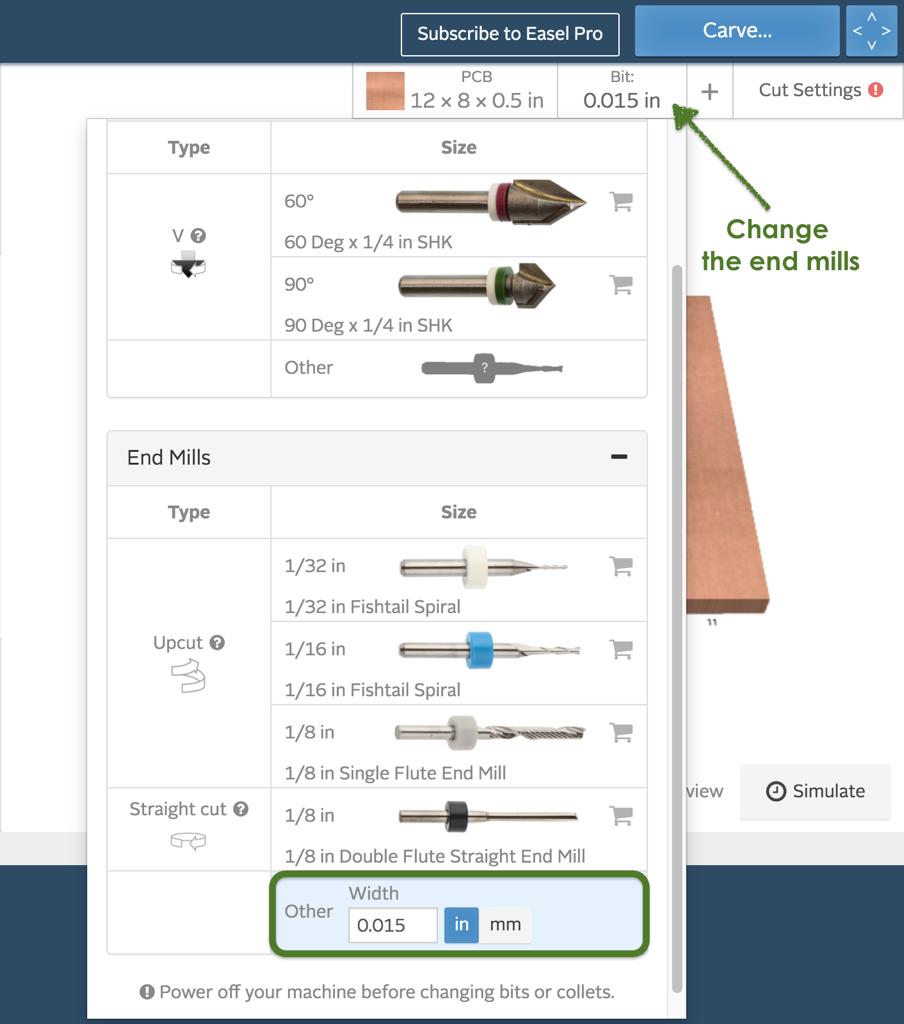
According to the tutorial, it is recommended to use (1/64 inch) bit size for the PCB traces, and (1/32 inch) end mill for the outline.
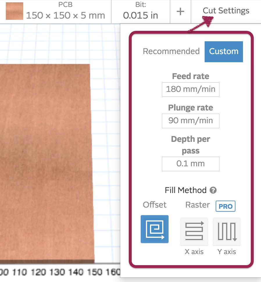
After that I adjusted the cut settings as the list below:
-Feed rate = 180 mm/min
-Plunge rate = 90 mm/min
-Depth per pass = 0.1 mm
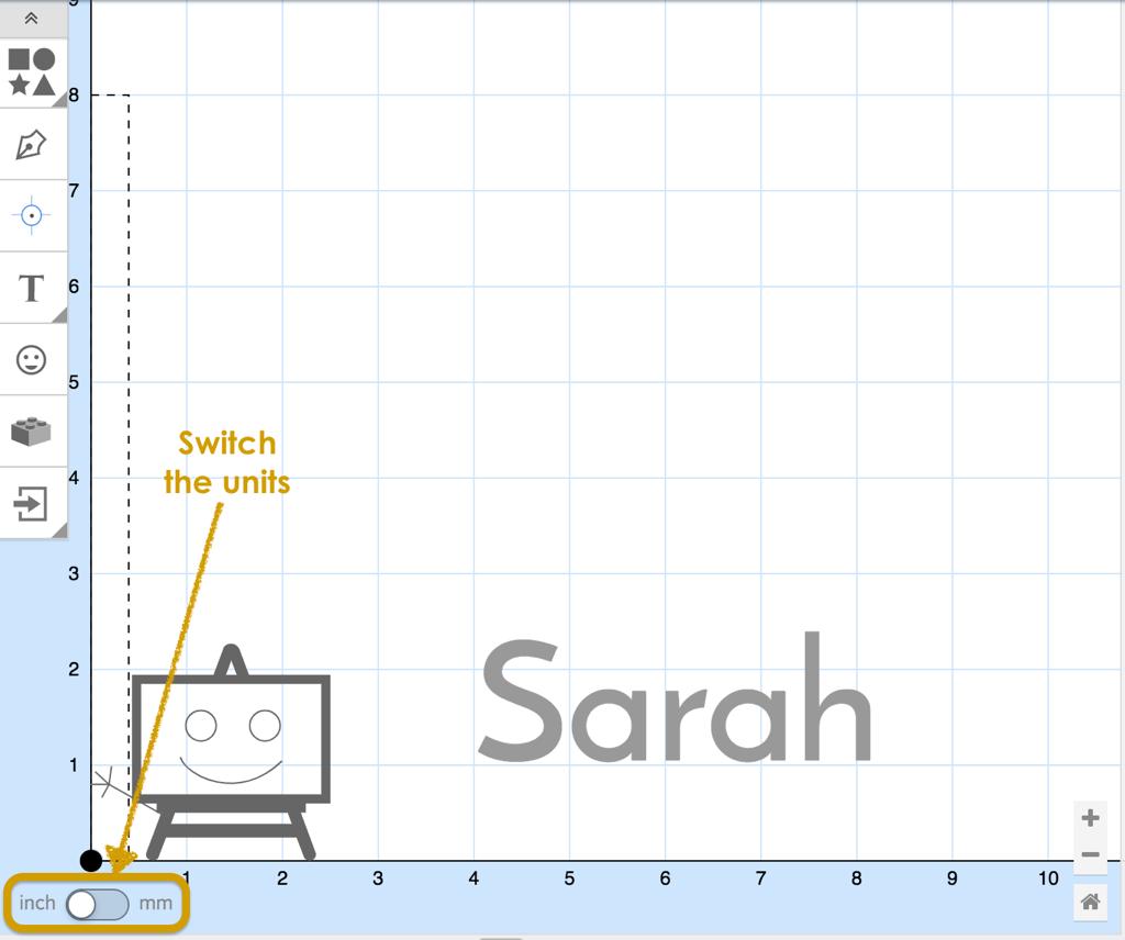
Usually I prefer to use a millimetre unit rather than inch for that I switch the units from the box that is located in the bottom of the left corner.
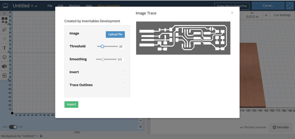
Now after everything was set up, it is time to bring the FabTinyISP traces to the workplace by clicking on the import button and selecting “ Image Trace “. Then, uploading the image from the computer.
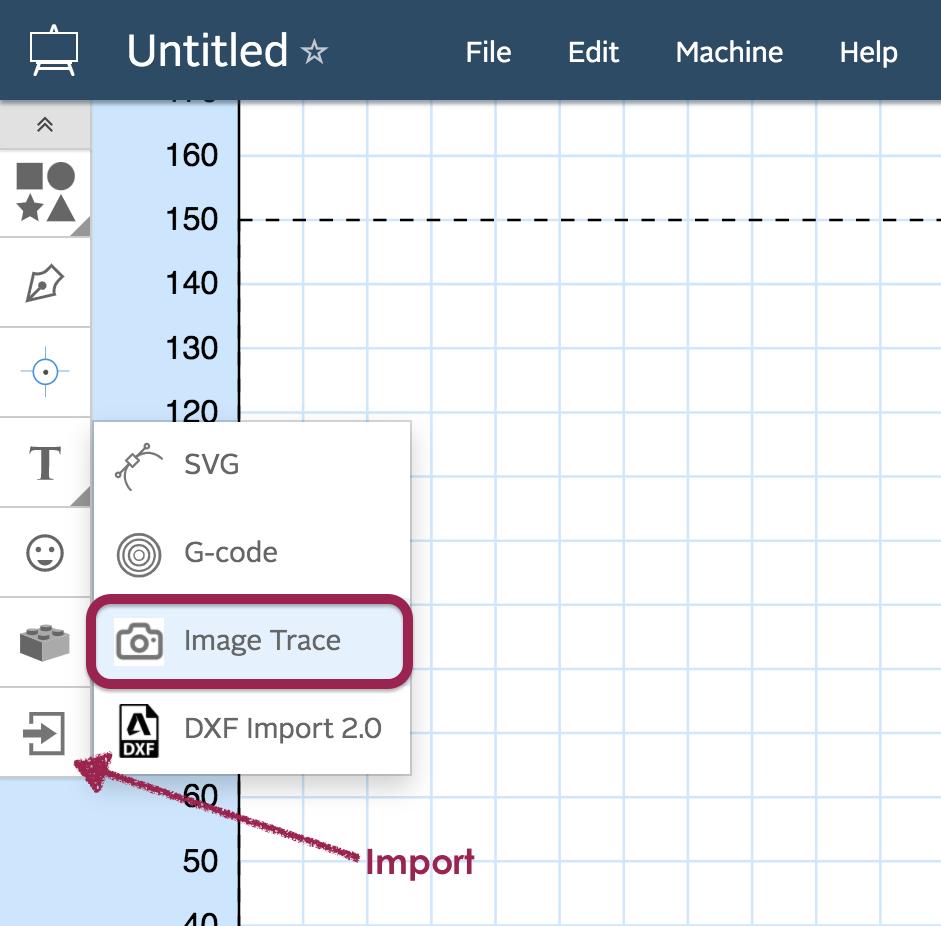
Image trace feature allows you to adjust the threshold and smoothing of the traces image as you need.
After importing the image to the workplace, I moved the design to the corner to reduce the wastage of the material.
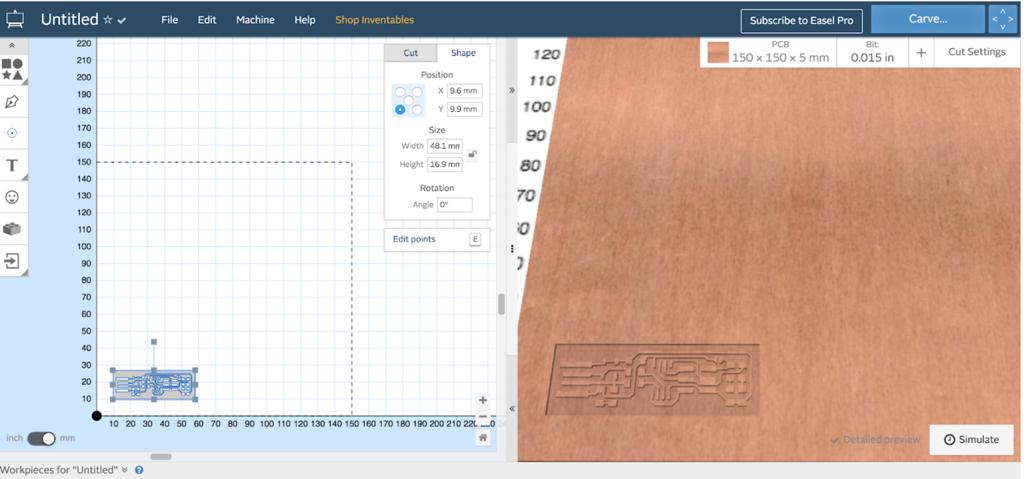
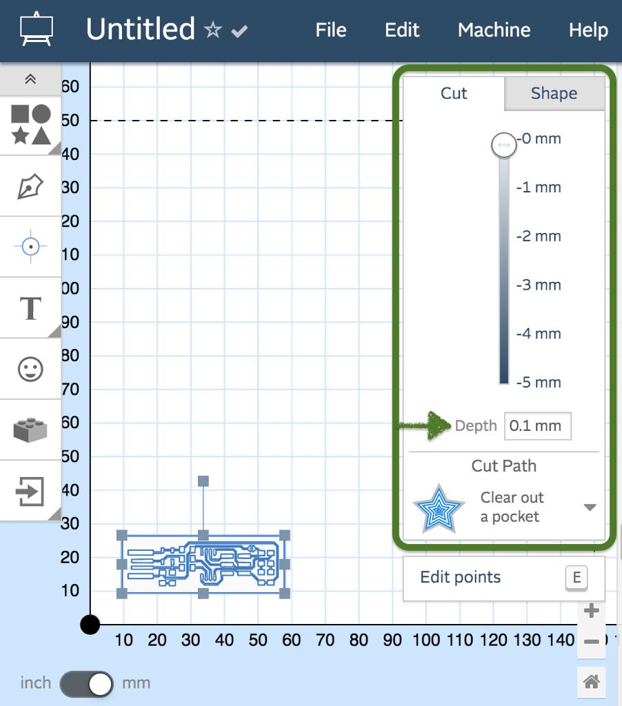
When I selected the design, a menu appeared that includes cut and shape settings. I selected the cut menu and set the cut depth to (0.1).
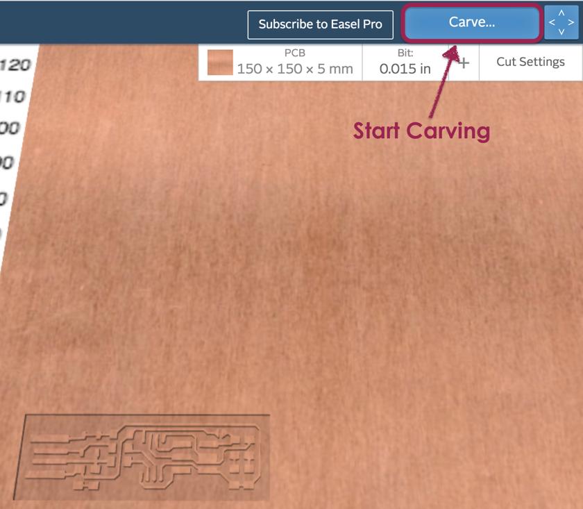
The last step is to connect the usb cable to the “Carvey” then click on the Carve button to start carving !
This is the result of the traces after the milling process.
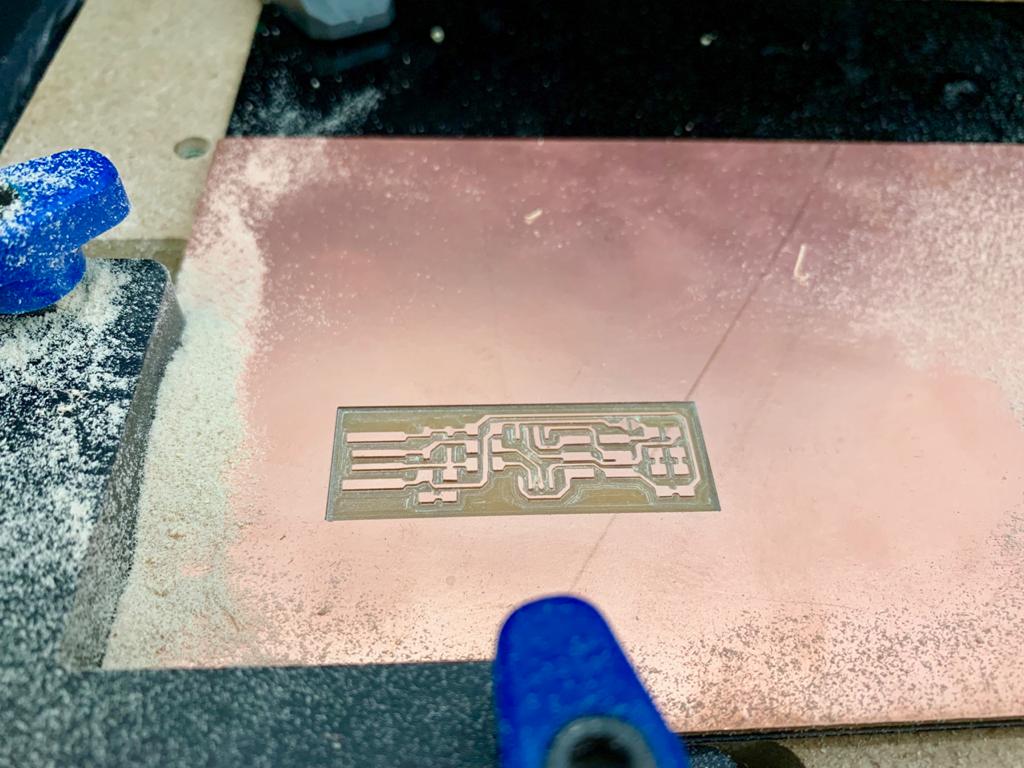
Cutting the outline is the final step of the PCB Fabrication. I imported the outline and changed the cut depth. Also, I changed the bit to another end mill for cutting the outline.
Done !
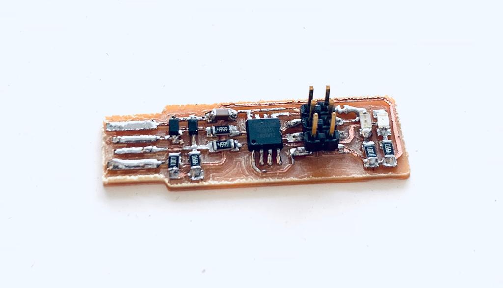
The PCB is ready for soldering !
Soldering the PCB
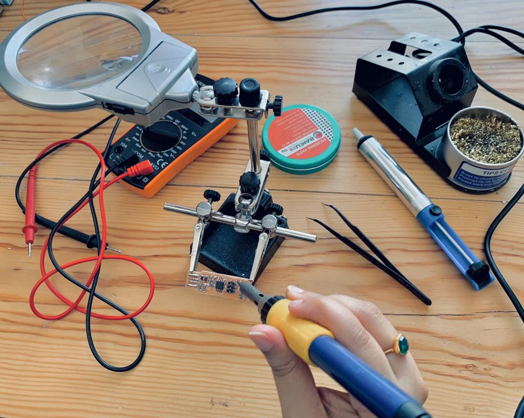
Soldering the PCB is the most exciting part for me because it is my first time using the soldering iron. As a beginner at soldering, it is normal to face some difficulty doing this. First our instructor Mr.Yousef Alsenwar showed us how to use it properly.
Now it is my turn !
The components list :
1 ATtiny45
Different types of resistors:
2x 3.3v zener diodes
1x 100nF (0.1µF) capacitor
1 ATtiny45
1x 2x3 pin header
2 LED’s :
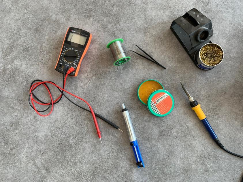
The soldering tools:
Soldering iron
Tweezers
Solder sucker
Solder spool
Helping hand
Tip tinner
Multimeter
I heated up the soldering iron by adjusting the temperature.
Oops !
I had some soldering problems, one of them was the tiny components and the PCB board moved all the time. I used the helping hands to make the board stable.
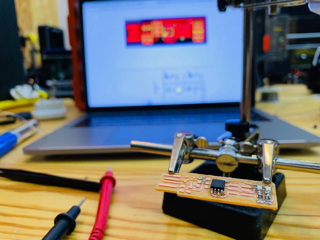
Also, after using the multimeter which is the short circuit detector, I noticed some traces were too close to each other because the milling machine didn't cut them properly. The solution for this problem is using the cutter to make a space between the paths. When the solder refuses to flow, I cleaned the tip by dragging it through a brass mesh.
Oh no!
I burned the LEDs many times and I soldered the microcontroller in the wrong orientation!
Ok Sarah do not panic ! and fix it.
I used the Solder sucker, It is a helpful tool to desolder the component that needed replacement.
Now, after checking and comparing between the schematic and the PCB board, I bridged the jumper to make the board ready for programming. .
Let's programming !
As a Windows user, I followed all the steps in this tutorial to program my PCB.
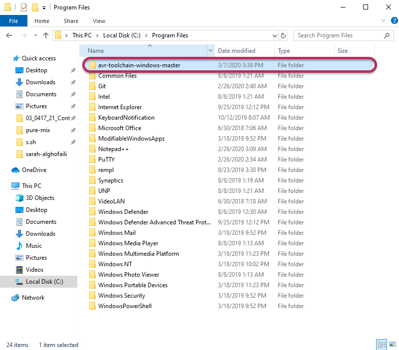
I downloaded and installed all the important software to program the FabTinyISP and make it a programmer:
1) The Atmel GNU Toolchain which is used to create applications for AVR microcontrollers.
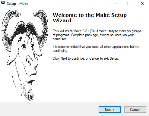
2) the GNU Make which is a build tool that is used to execute repetitive tasks.
3) Avrdude.
Next, I updated the PATH by opening the Start menu >Control Panel > System > Advanced System Settings > Environment variables. Also, I selected Path and clicked the “Edit” button.
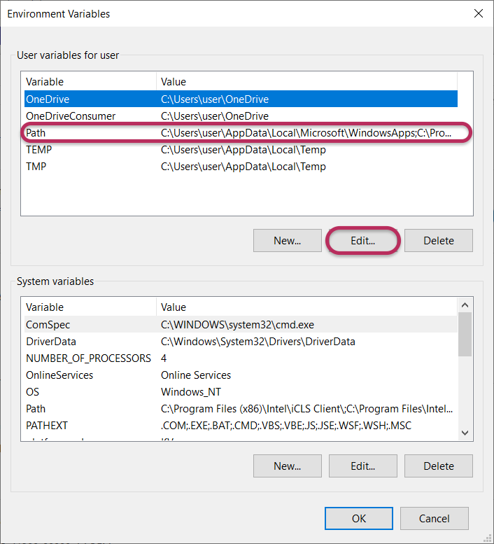
Then, I added the location for each tool by clicking on “New” button and “OK” button when finished.
After that, I downloaded the firmware source code then extracted the zip. Inside the firmware folder, I clicked on “Git Bash here” to get the right path of firmware and I inserted theses commands :
make clean to remove .hex files and get a clean build.
maketo build the .hex file
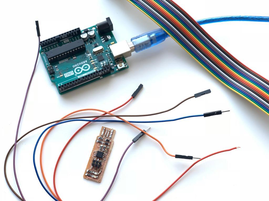
After this step, I need to make the arduino work as a programming board, so I opened the Arduino software to upload the ArduinoISP code to the Arduino Uno board. According to the com port that is shown in the Arduino when I plug It, I edited the make file to replace COM10 to COM4.
Then, I connected my PCB to the Arduino by using 6 pins.
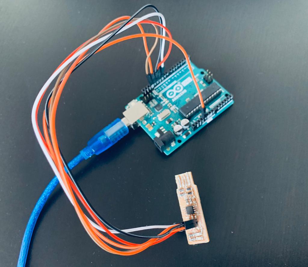
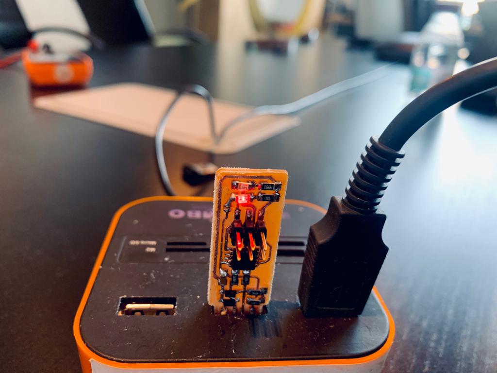
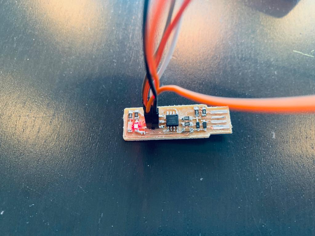
Now, the LED is lighting up.
Returning to the Git Bash, I wrote these commands :
make flashto use the programmer to load it onto the target chip.
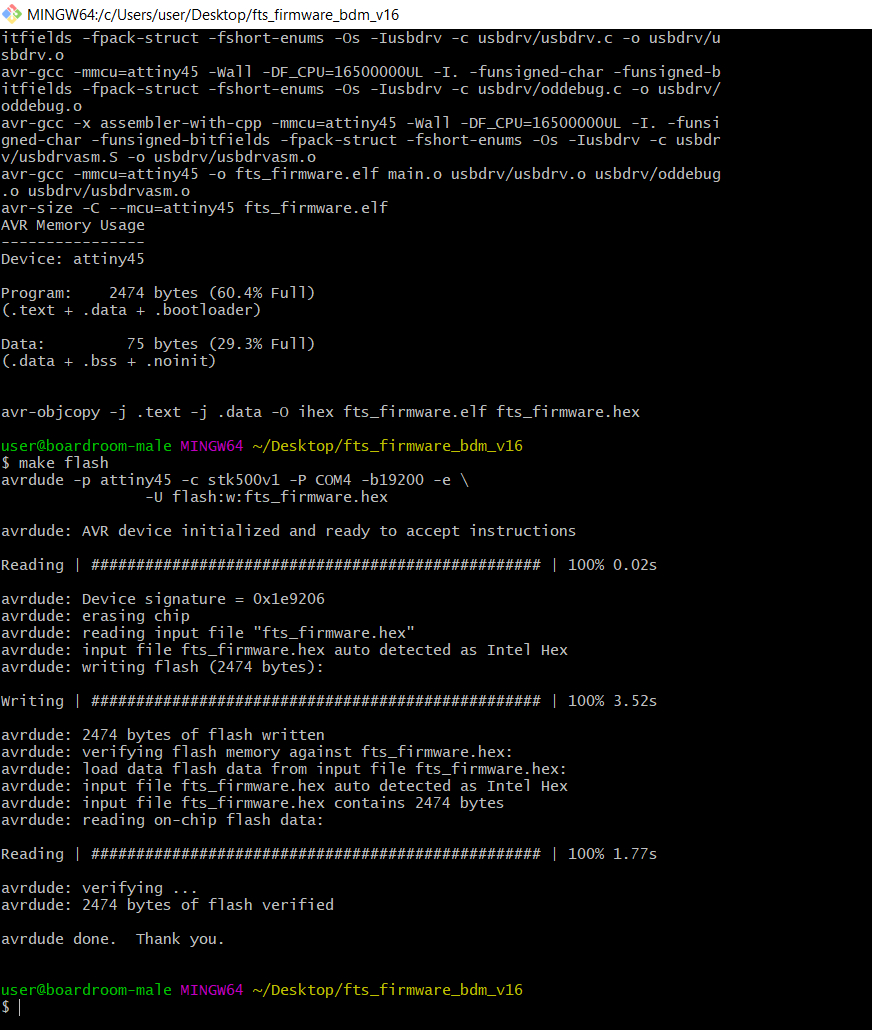
make fusesto program the fuse bits on the target chip.

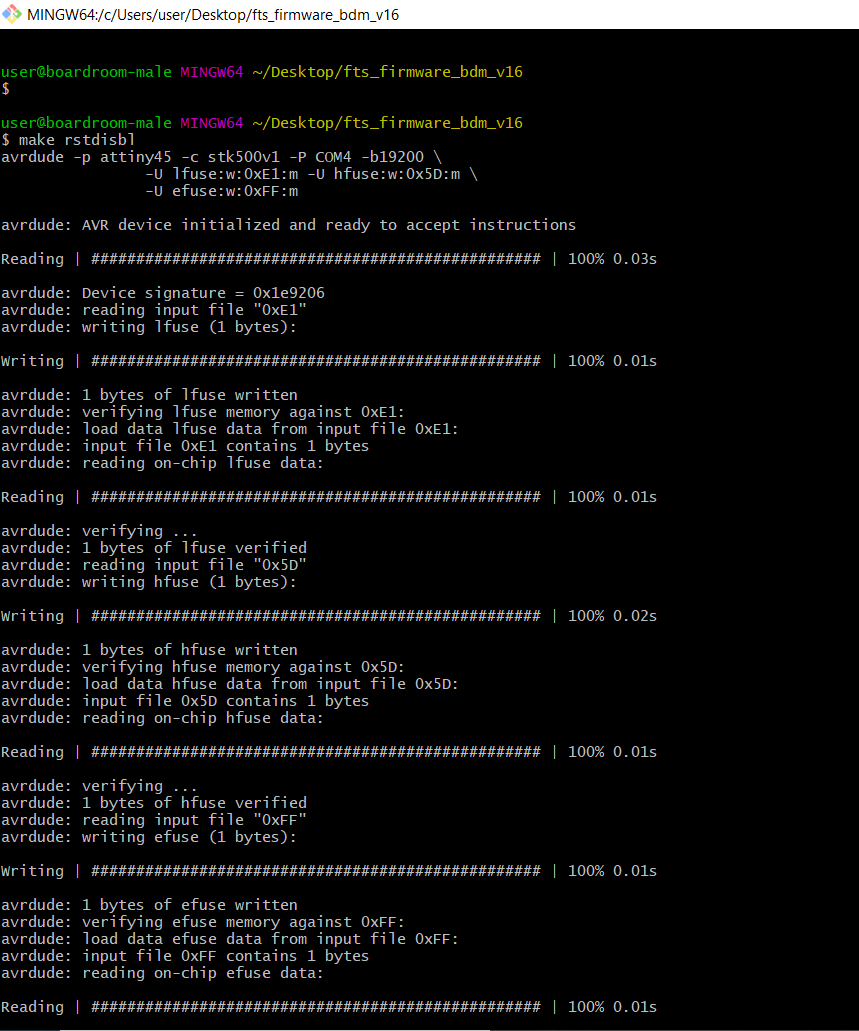
make rstdisblto blows the reset fuse.
Finally, I used a usb hub to connected to the ISP.
Yay !
I did it