Fifteenth assignment
Date
6 May 2020
This week's assignment aimed to design, build, and connect wired or wireless node(s) with network or bus addresses.
What is Networking and communication ?
Network is a group of two or more systems linked together by communications channels to share data and information.
Communication is the exchange process of the digital data between two or more devices over a transmission medium.
A computer network has four main types:
LAN(Local Area Network)
PAN(Personal Area Network))
MAN(Metropolitan Area Network))
WAN(Wide Area Network))
What is protocol ?
A protocol is a set of rules and standards that basically define a language that devices can use to communicate.
There are two types of Communication Protocols:
Wireless Communication
Wired Communication
The wired communication is divided into two categories:
Internal Communication:
1. I2C
2. SPI
External Communication:
1. Ethernet
2. RS-232
3. RS-485
4. UART
5. USART
6. USB
In this assignment, I decided to build a wired network by using the I2C protocol.
What is I2C protocol ?
I2c stands for Inter-Integrated-Circuit, it is one of the most famous serial communication protocols that allows different devices to exchange their data with each other.
Each device in the I2c communication takes a specific role, It is either a master or a slave. In addition, all the devices in the bus have a unique address.
How many wires are required for I2C communication?
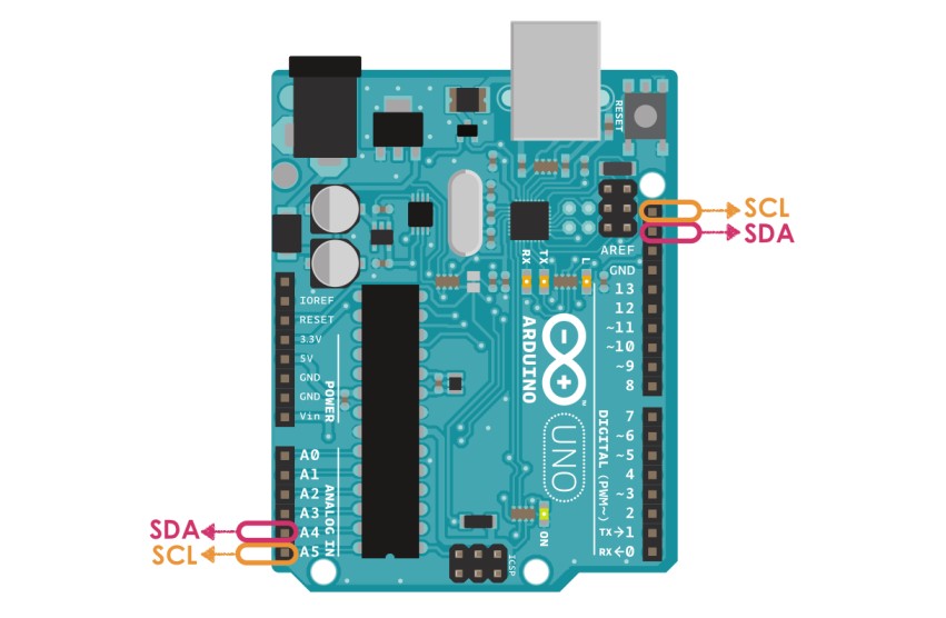
Only two bus lines are required :
DA (Serial DAta) : The line for the master and slave to send and receive data.
SCL (Serial CLock) :The line that carries the clock signal.

I2c is synchronous communication, as Prof. Nail explained, the difference between synchronous and asynchronous transmissions is :
Synchronous is the exchange of data between sender and recevier devices in the real-time and via synchronized clock.
Asynchronous is the exchange of data between sender and recevier devices without the requirement for the recipients to respond immediately.
Also, I2c is considered as half duplex communication which means it transmits and receives data but not at the same time.
HOW I2C Communication WORKS ?
Both master and the slave are connected with the same data and clock buses and the master always initiated and finished the communication.
Start Condition: The SDA line switches from a high voltage level to a low voltage level before the SCL line switches from high to low.
Stop Condition:The SDA line switches from a low voltage level to a high voltage level after the SCL line switches from low to high.
Address Frame: A 7 or 10 bit sequence unique to each slave that identifies the slave when the master wants to talk to it.
Read/Write Bit: A single bit specifying whether the master is sending data to the slave (low voltage level) or requesting data from it (high voltage level).
ACK/NACK Bit: Each frame in a message is followed by an acknowledge/no-acknowledge bit. If an address frame or data frame was successfully received, an ACK bit is returned to the sender from the receiving device.
i2c pin locations
Let’s dive into the wiring part !
I started the I2c communication by determining one arduino board as Master and the other board as Slave. As I mentioned before, the SCL line is used for the clock, and the SDA line for the data, I connected SCL and SDA in the master board with the same pins in the slave board. Also, I linked the GND pins in both boards together.
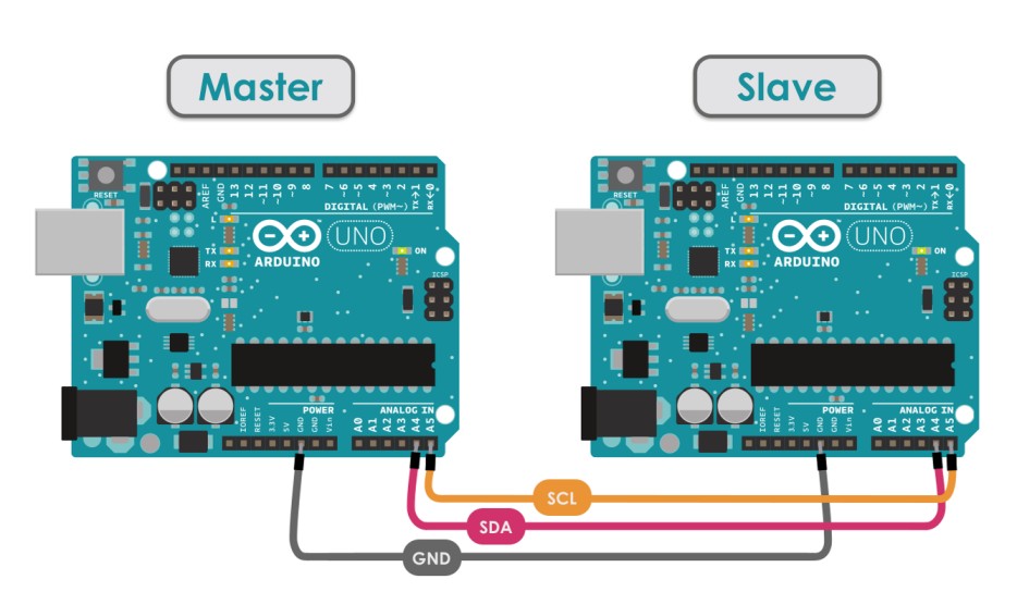
At this point , the boards were ready to start the I2c communication.
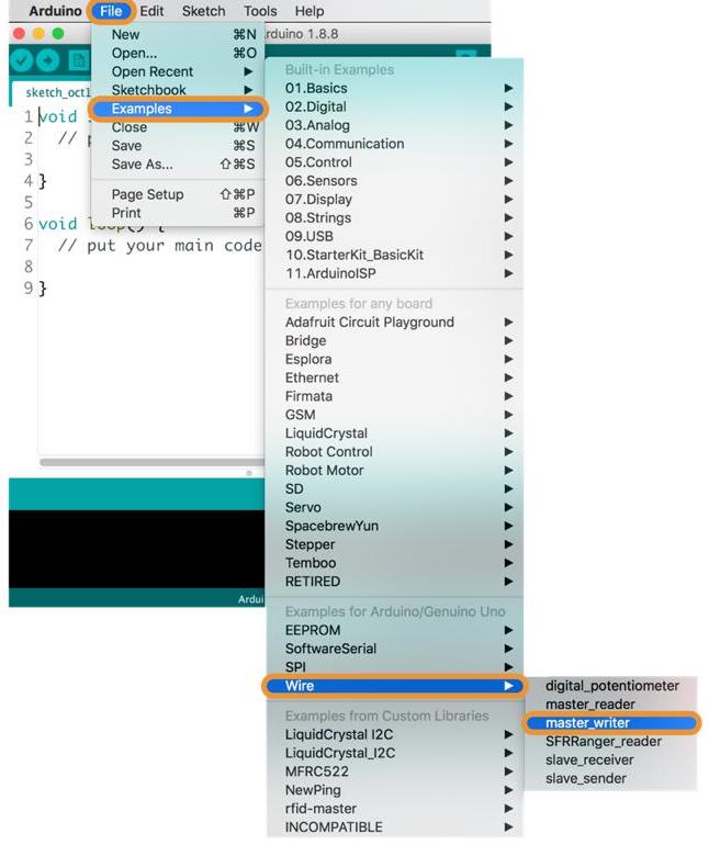
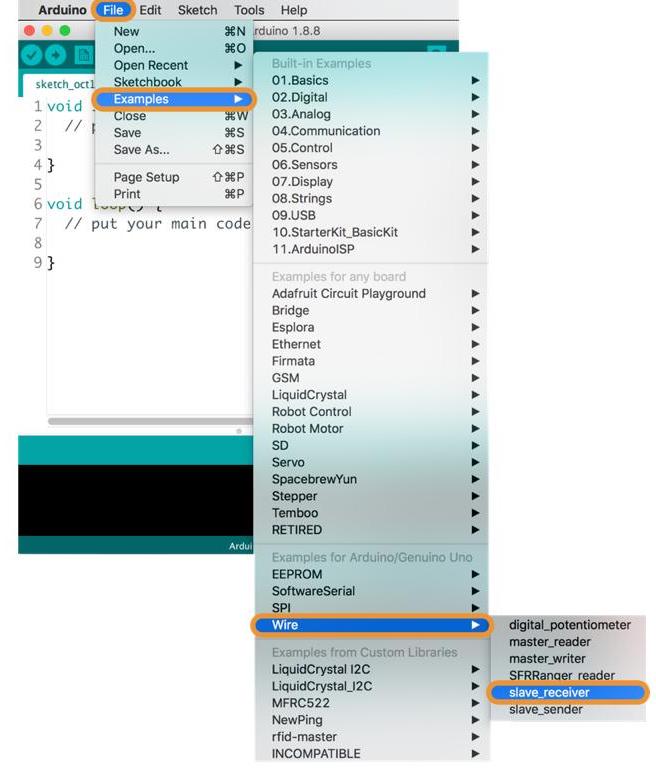
I opened the IDE Arduino to write separate code for each board. I started with the master.
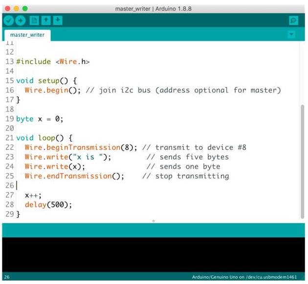
The Master code :
Include the Wire.h library which is the library that allows the I2c communication between the master and slave devices.
#include <Wire.h>
In the void setup() section :
Write the serial begin to serial for output
Serial.begin(9600);
initiates the Wire library and Join i2c bus by determining the address but it is optional for the master.
Wire.begin();
Then, print the message
Serial.println("I am I2C Master");
In the void loop() section :
begin with device address 8
Wire.beginTransmission(8);
Sends hello string
Wire.write("Hello Slave");
Stop transmitting
Wire.endTransmission();
Request and read 9 bytes from slave device by writing Wire.requestFrom(address, quantity)
Wire.requestFrom(8, 9);
Retrieve the bytes, the slave may send less than requested
while (Wire.available())
read data received from slave
char c = Wire.read();
Then, print the character
Serial.println(c);
Serial.println();
Pauses the program for amount of time (1000 milliseconds)
delay(1000);
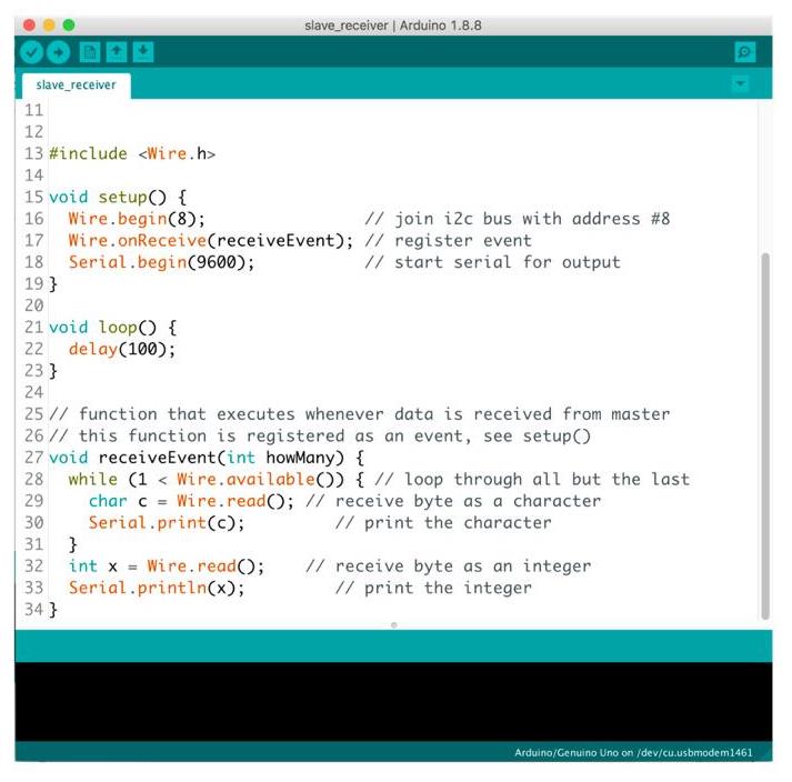
The Slave code :
Like the master, Include the Wire.h library
#include <Wire.h>
In the void setup() section :
Initiate the Wire library and join the I2C bus with address #8
Wire.begin(8);
Register receive event
Wire.onReceive(receiveEvent);
Register request event
Wire.onRequest(requestEvent);
Write the serial begin to serial for output
Serial.begin(9600);
Serial.println("I am I2C Slave");
In the void loop() section :
Pauses the program for amount of time ( 100 milliseconds)
delay(100);
function that executes whenever data is received from master
void receiveEvent(int howMany)
while (0 <Wire.available())
To receive a byte as character
char c = Wire.read();
Then, print the character
Serial.println(c);
Serial.println();
Write a function that executes whenever data is requested from master. It is registered as an event.
void requestEvent()
Send the response message that the master expected.
Wire.write("Hi Master");
The Master code :
The Slave code :
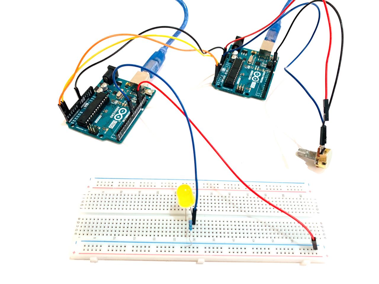
After testing the I2c communication, I decided to add sensor and output devices.
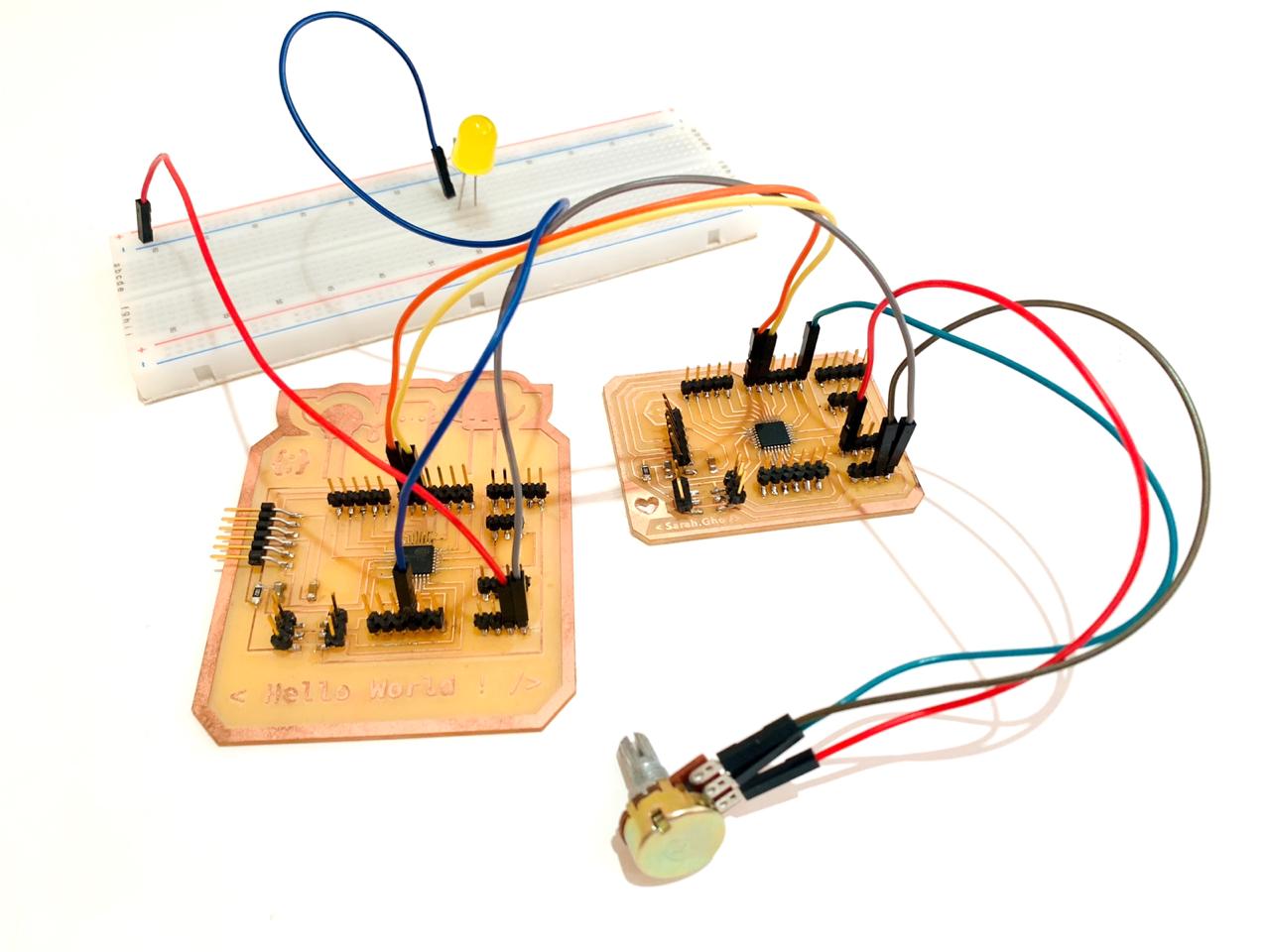
I2C Between Arduinos With Potentiometer and LED
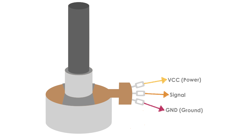
I used a Potentiometer, a simple knob that provides a variable resistance into the Arduino board as an analog value that controls the rate at which an LED blinks. It has three pins:
The first pin connected to the ground.
The second pin, which is located In the middle of the Potentiometer, connected to V0 (VEE).
The third pin connected to the +5 volts.
1 x Breadboard
2 x Arduino Uno
1 x One LED
1 x Potentiometer
1 x 220 Ohm resistor
Jumper wires
The Master code :
I started by Including the Wire.h library which is the library that allows the I2c communication between the master and slave devices.
#include
int x = 0;
I selected the input pin for the potentiometer
int sensorPin = A0;
Also, I established a variable to store the resistance value that coming from the sensor
int sensorValue = 0;
In the void setup()function:
I started the I2C Bus as Master
Wire.begin();
I initialized serial communication at 9600 bits per second
Serial.begin(9600);
In the void loop()
The code will make the board read the potentiometer value connected to pin A0, and save that value in the variable.
sensorValue = analogRead(sensorPin);
To print out the value in the serial window
Serial.println(sensorValue);
Wire.beginTransmission(address) used to Begin a transmission to the I2C slave device with the given address.
Wire.beginTransmission(9);
To send value:
Wire.write(sensorValue);
To wait for a second:
delay(1000);
Then, ends the transmission to a slave device that was begun by beginTransmission() and transmits the bytes that were queued by write().
Wire.endTransmission();
The Slave code :
As the master code, I started the code by including the required Wire library for I2C.
#include
Next, I defined the LED Pin
int LED = 9;
int x = 0;
In the void setup() ,defined the LED pin as Output
pinMode (LED, OUTPUT);
After that, I started the I2C Bus as Slave on address 9
Wire.begin(9);
Then, attached a function to trigger when something is received.
Wire.onReceive(receiveEvent);
transfer bit rate for data over Serial communication
I initialized serial communication at 9600 bits per second
Serial.begin(9600);
Called when the master writes to this slave. this function is registered as an event
void receiveEvent(int bytes)
To read one character from the I2C
x = Wire.read();
In the void loop()
Potentiometer value from sensor
int ledPWM = map(x, 0, 255, 0, 1023);
analogWrite(LED, ledPWM);
Serial.print("X is: ");
Serial.println(x);
Serial.print("PWM is: ");
Serial.println(ledPWM);
delay(1000);
The Master code :
The Slave code :
I tested the I2C communication codes between the Master and Slave Arduino Boards.
The next step, I uploaded the code to the PCBs.
Code Files :
Arduino IDE : Master Code
Arduino IDE : Slave Code
Arduino IDE : Master Code - Potentiometer+LED
Arduino IDE : Slave Code - Potentiometer+LED