Twelfth assignment
Date
This week assignment is required to modify our board that we have designed before, by adding an output device and testing it.
As I mentioned before, I used the Arduino board instead of a new PCB which I will fabricae once the COVID-19 quarantine is over.
There are many types of output devices, such as LEDs Lights، LCDs and motors.
I decided to test two of the output devices :
DC motor.
LCD display.
DC motor
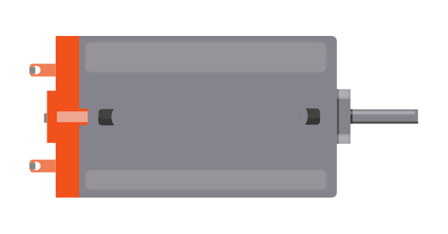
What is DC motor ?
DC ( Direct Current ) motor is a device that works in a rotation form by converting electrical energy into mechanical energy.It has two wires, one positive (+) and one negative (-).
At the beginning, I Identified the components that I need to run the DC motor.
The components list :
1 x Arduino board
1 x Breadboard
5 x Jumper Wires
1 x 220 Ω Resistor
1 x Diode
1 x NPN Transistor
1 x DC Motor
The DC motor usually uses more power than an Arduino digital output can handle. For that reason, using the NPN transistor is necessary to prevent damaging the Arduino board because it works as a switch that uses little current from the Arduino output to control the high current of the motor.
Also, using the diode, which allows electricity to flow in one direction, will protect the Arduino from damage because it shortens the reverse negative voltage that is generated when the motor is turned off.
Before starting connecting the components, I checked the circuit using the Tinkercad simulator.
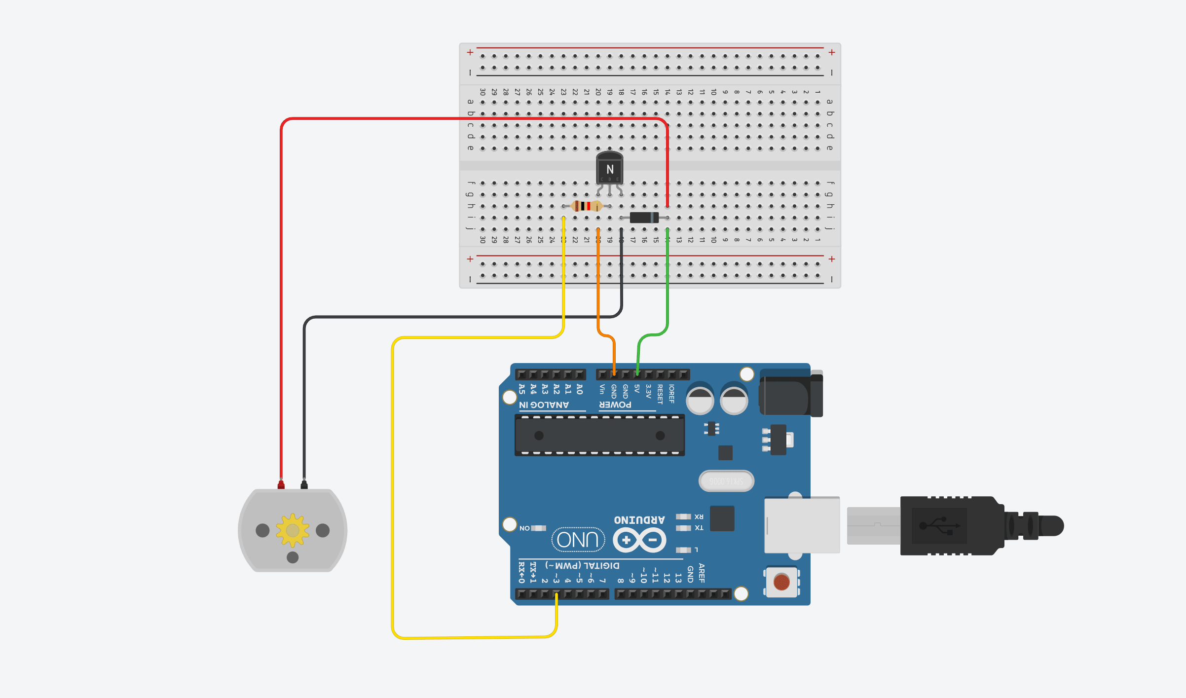
After the simulation, I wired up all the components to create the circuit.
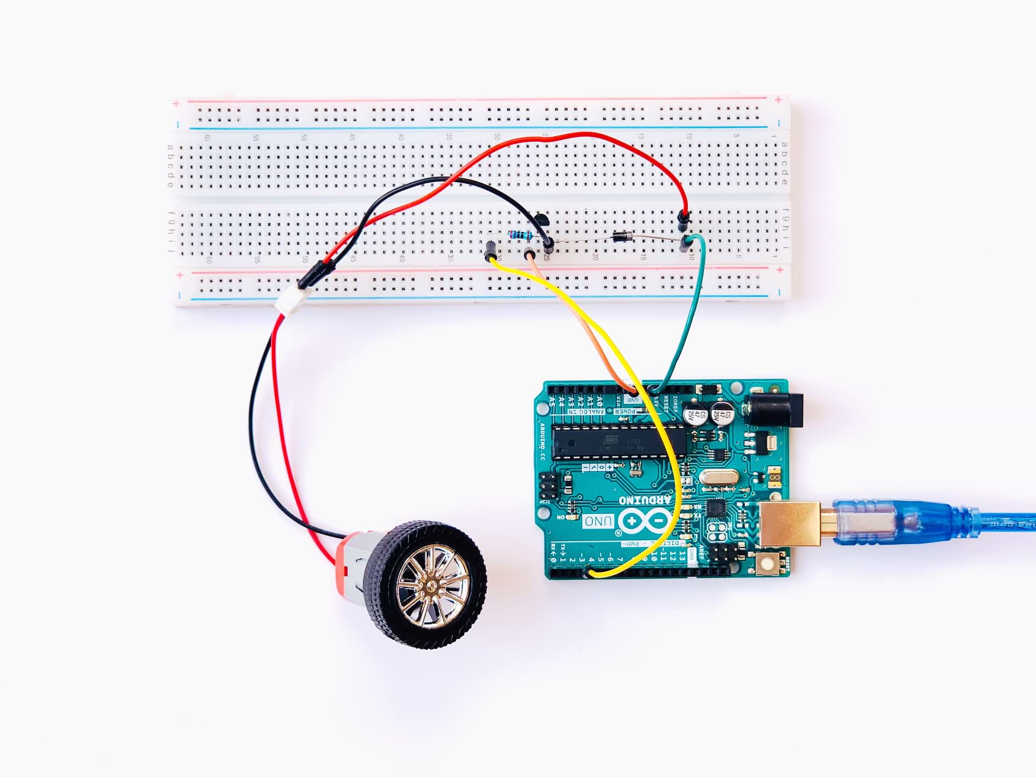
Then, I opened the Arduino platform to upload the code to the board.
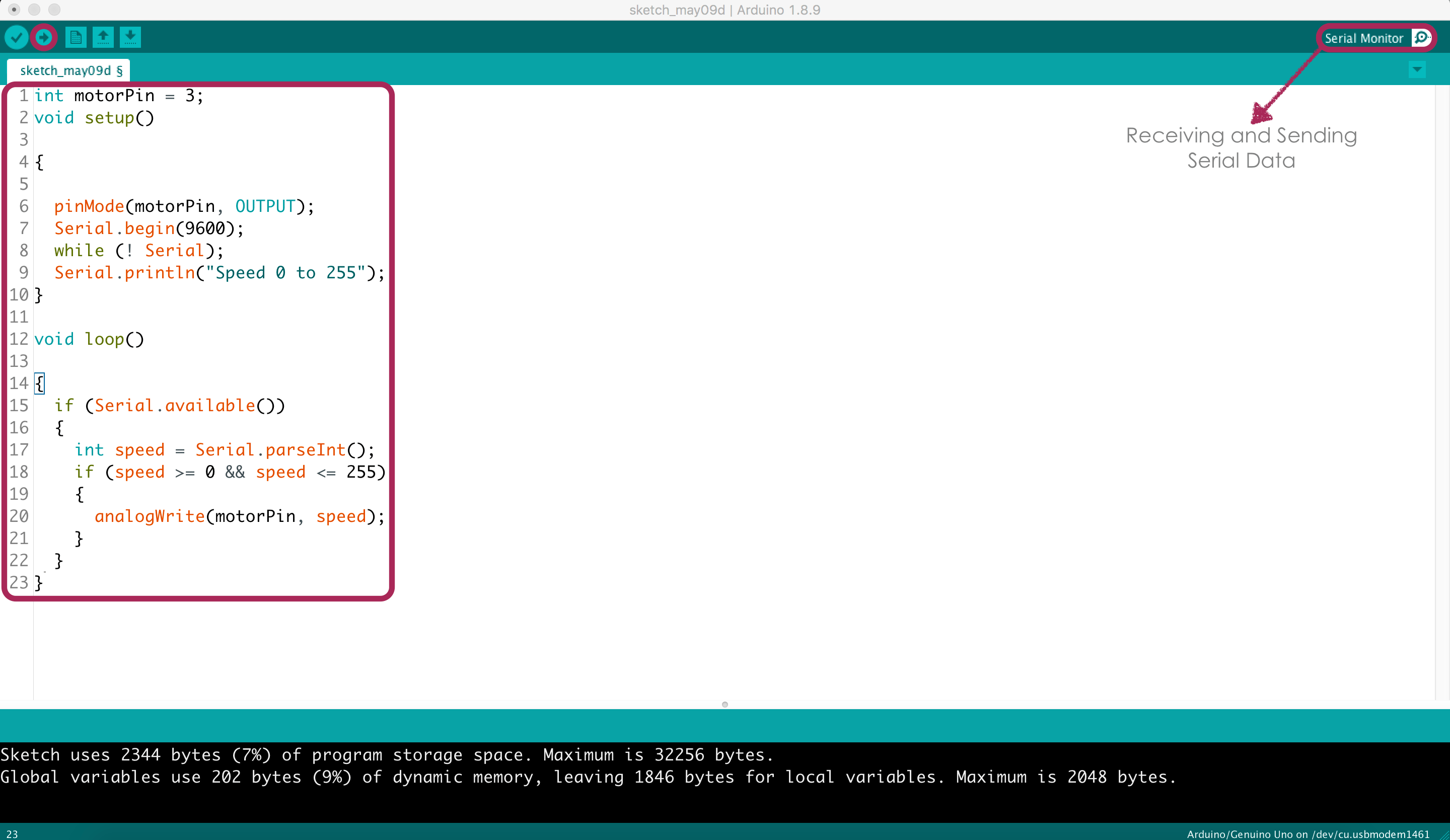
PROGRAMMING
To write the code I followed these steps:
Set the pin that attaches to the resistor and controls the motor.
set the motor pin as an output.
Start serial communication by writing the serial begin command.
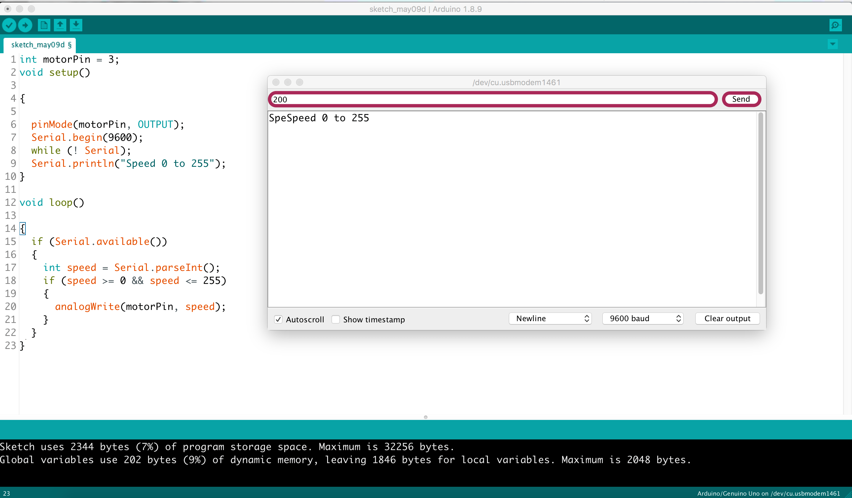
Open the Serial Monitor and give the values that control the speed of the motor.we need to enter a value between 0 and 255.
Use Serial.parseInt command to read the number entered as text in the Serial Monitor and convert it into an 'int'
Use If statement to make sure that the value entered falls in the actual range.
To make the DC motor rotate, rite the speed value to the motor.
GND: Ground (0V)
VCC: Supply voltage (+5V)
VEE: (V0) Contrast adjustment via variable resistor (Potentiometer)
RS: Stand for register select, and it is responsible for sending commands (Low) or sending characters to the LCD (High)
R/W: Stand for read/write,and it is responsible for giving an instruction to the LCD (Low) or reading information from it (High)
En: Stand for Enable, and it is responsible og sending data to data pins when a high to low pulse is given
D0 to D7: 8-bit parallel data pins
LED + : Anode pin
LED - : Cathode pin
1 x Arduino Uno board
1 x Breadboard
16 x Jumper Wires
LCD 16 x 2
Potentiomete
1 x 220 Ω Resistor
The first pin connected to the ground.
The second pin, which is located In the middle of the Potentiometer, connected to V0 (VEE).
The third pin connected to the +5 volts.
Call "Liquid Crystal" library to the sketch which is an inbuilt library.
initialize the library by associating the LCD interface pins that connected to the arduino pins
Make custom characters.
Specify the LCD's number of columns and rows.
Set the cursor to column 0, line 1 which is the second row.
Print a message to the LCD.
Print the custom character
int motorPin = 3;
In the void setup() section :
pinMode(motorPin, OUTPUT);
Serial.begin(9600); //
while (! Serial);
Serial.println("Speed 0 to 255");
In the void loop() section :
As long as the Serial monitor is available, enter the motor speed.
if (Serial.available()
int speed = Serial.parseInt();
if (speed >= 0 && speed <= 255)
analogWrite(motorPin, speed);
To control the speed of the motor، I clicked on The Serial Monitor button and sent a number between 0 and 255
I tried different values of DC motor speed for example 150, 200 and 255.
Yes ! the motor is spinning perfectly!
LCD display
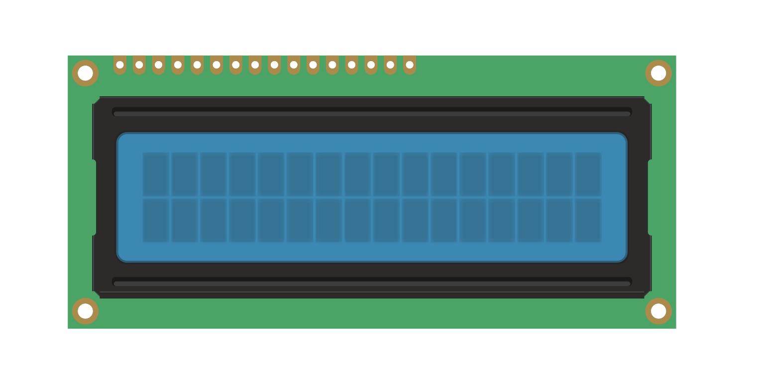
What is LCD display ?
I used the 16 x 2 LCD display which is the most common LCD type. 16 x 2 means it has 16 Columns and 2 Rows.
LCD Pin Configurations
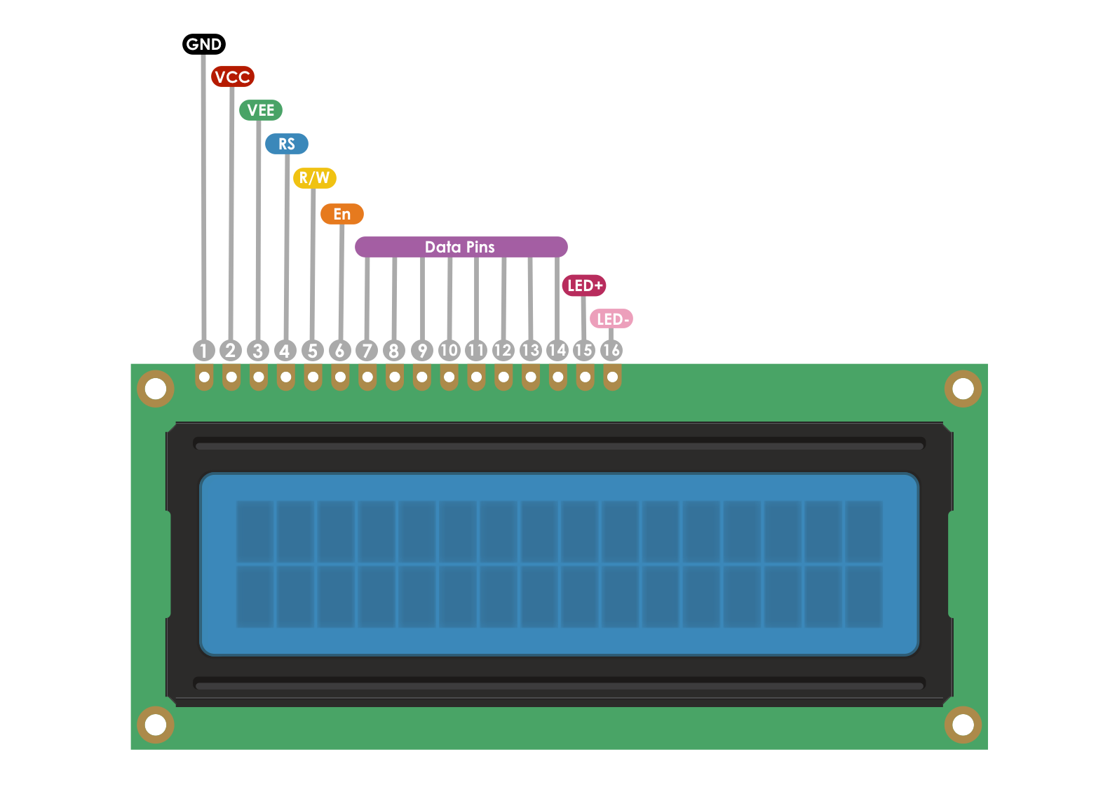
The LCD has 16 pins:
First, I collected all the components that I will need to make the LCD work and display a custom text.
The components list :
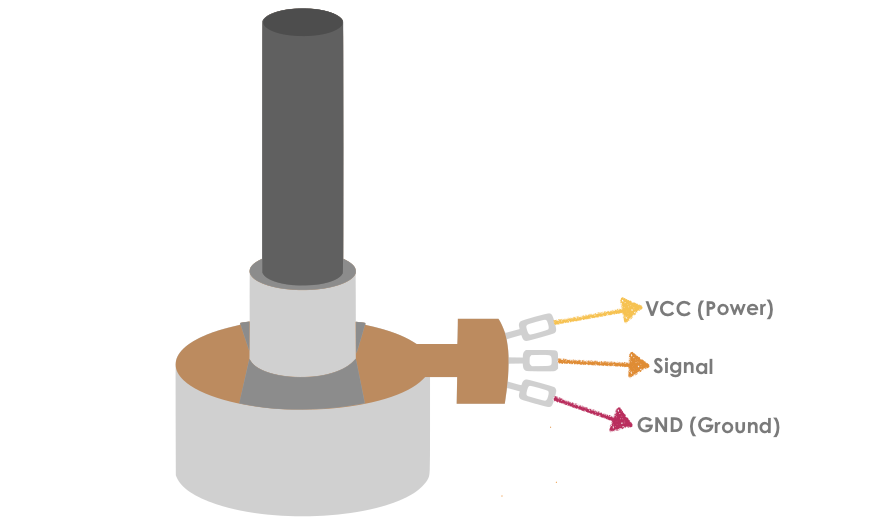
One of the components is the Potentiometer which is a variable resistor that is used with the LCD to vary the screen brightness. It has three pins:
Like the previous step , I used the Tinkercad simulator to test the circuit.
I forgot to add the resistor.
The LCD does not work because The LED needs a current limiting resistor to prevent excess current from burning it out.
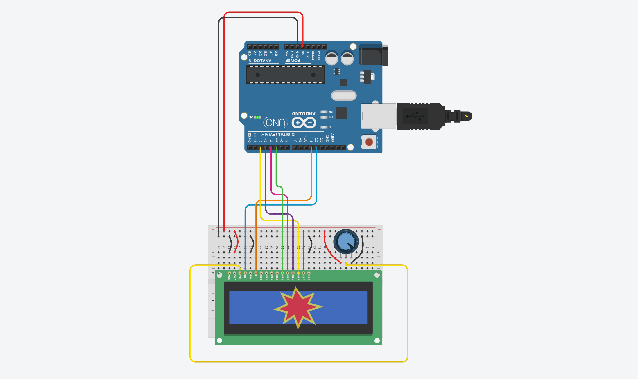
To solve this problem, I added 220 Ω Resistor!
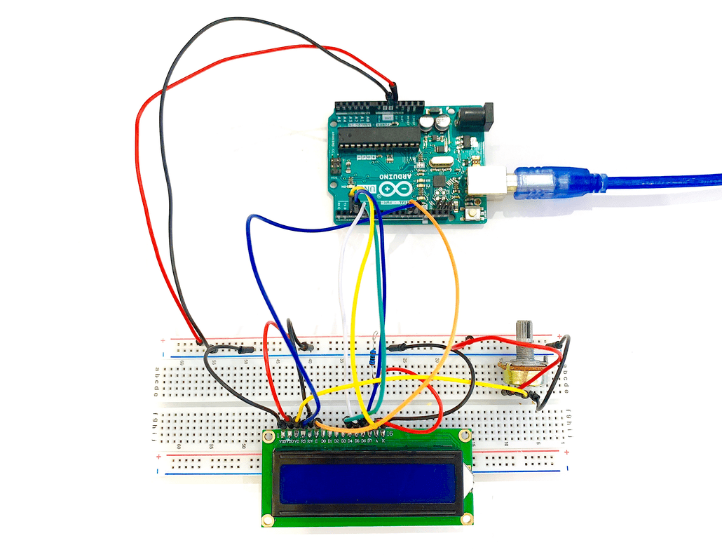
After that, I started wiring the physical components together.
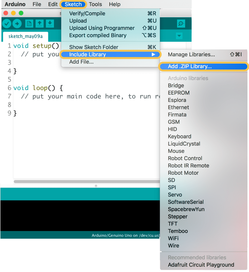
The last step was opening the Arduino IDE and uploading the code to the board but first I needed to add a new Arduino library. To do that, I clicked on the Sketch menu > Include Library > Add .ZIP Library.
PROGRAMMING
To write the code:
#include </LiquidCrystal.h>
const int rs = 12, en = 11, d4 = 5, d5 = 4, d6 = 3, d7 = 2;
LiquidCrystal lcd(rs, en, d4, d5, d6, d7);
byte Heart[] = {
B00000,
B01010,
B11111,
B11111,
B01110,
B00100,
B00000,
B00000
};
In the void setup() section:
lcd.begin(16, 2);
lcd.createChar(0, Heart);
}
In the void loop() section :
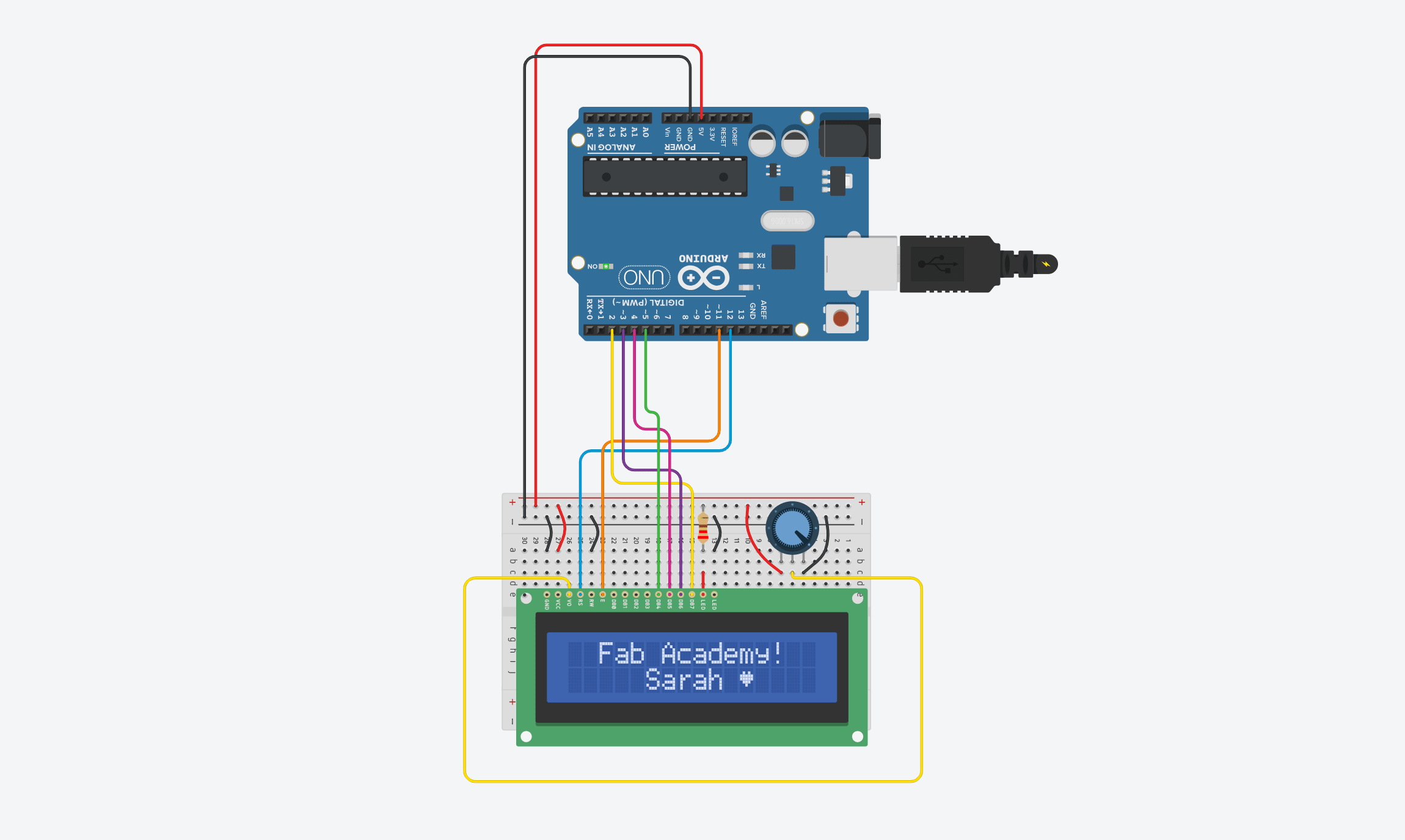
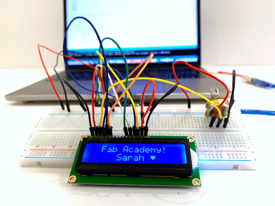
lcd.setCursor(2, 0);
lcd.print("Fab Academy!");
lcd.setCursor(5, 1);
lcd.print(" Sarah ");
lcd.setCursor(11, 1);
lcd.write(byte(0));
}
Buzzer
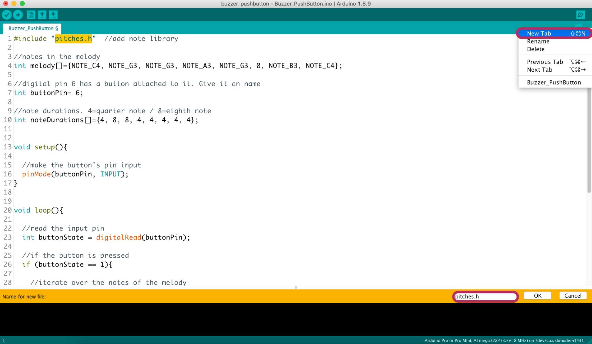
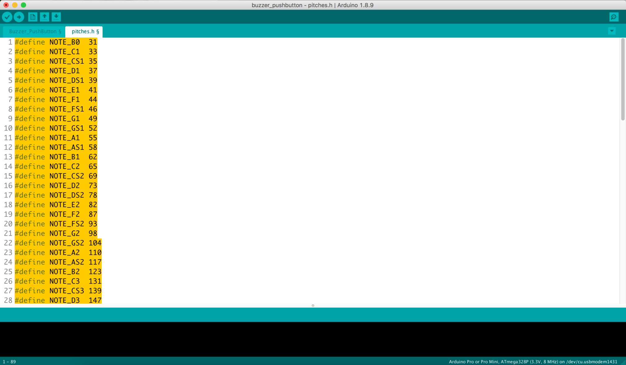
I started the code by including the "pitches.h" Library which is the note library.
#include "pitches.h"
To include the library in the sketch, I clicked on the “New Tab” button on the toolbar and created a new tab called pitches.h.
Defining the notes used in the melody.
int melody[]={NOTE_C4, NOTE_G3, NOTE_G3, NOTE_A3, NOTE_G3, 0, NOTE_B3, NOTE_C4};
Digital pin 6 has a button attached to it.
int buttonPin= 6;
Duration of each note should be corresponding to the notes above.4=quarter note / 8=eighth note
int noteDurations[]={4, 8, 8, 4, 4, 4, 4, 4};
In thevoid setup()
Making the button's pin input
pinMode(buttonPin, INPUT);
In thevoid loop()
To read the input pin
int buttonState = digitalRead(buttonPin);
If the button is pressed
if (buttonState == 1){
To iterate over the notes of the melody
for (int thisNote=0; thisNote <8; thisNote++){
To calculate the note duration, take one second. Divided by the note type
int noteDuration = 1000 / noteDurations [thisNote];
tone(8, melody [thisNote], noteDuration);
To distinguish the notes, set a minimum time between them. The note's duration +30% seems to work well.
int pauseBetweenNotes = noteDuration * 1.30;
delay(pauseBetweenNotes);
To stop the tone playing
noTone(8);
DOWNLOAD FILES :
Code files:
Resources: