Exercise 15 - Molding and Casting14/5/2020 to 20/5/2020
There are 2 tasks for this week:
- Individual Assignment:: Design a 3D mould around the available stock and tooling, mill it and use it to cast parts. Mold must uses 3-axis finish cut),
- Group Assignment:: Review the safety data sheets for various molding and casting materials.
The group assignment is done with Noel Kristian, Yeo Gau Siong and Lucas Lim.
Due to Covid-19 situation, we are all working from home (WFH) and has limited opportunity to test out different molding and casting materials. The group assignment hence focussed primarily on the review of the Safety Data Sheet of the molding and casting chemicals that SP Fablab has acquired or tried before. Our collective work is documented on the SP Fablab Website
.Individual Assignment
The individual assignment is divided into 3 subsections, namely:
- Mold Design
- Tool Path Generation & Milling the mold
- Casting and Molding
Part 1: Mold Design Using Fusion 360
Referring to the works of past students from SP Fablab, the design for almost all the molds requires only 2.5-axis milling. For our FabAcademy 2020 batch however, the Composites assignment was removed and in its place, the requirement for the mold design is tightened to one that must require 3-axis milling.
In order to cast an object properly, it is important to distinguish between negative and positive molds. Negative molds have concave cavities while positive mold has a convex shape. For this assignment, I plan to first design and produce a positive mold out of blue foam using 3-axis milling peocess. Thereafter, I will make a negative mold by pouring casting silicone onto this milled object. With the negative mold I can then make many replicates of the positive mold easily.
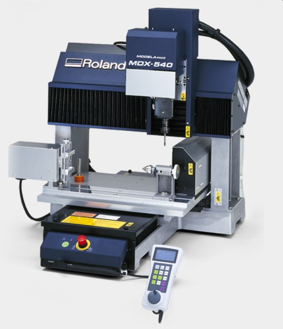
For the milling, SP Fablab has one unit of the Roland Modela ProII MDX-540 desktop CNC machine. The MDX-540 has a rotary axis to allow users to rotate an object until all 4 sides have been milled as well an automatic tool changer that changes up to 4 preset tools. For our machine, 6mm, 4mm, 3mm and 2mm square bit are used and the stock is secured onto a flatbed meaning only 3-axis milling is possible.
For this assignment, we are told that blue high density foam will be used as the stock. With no experience of this material, I read Singapore FabAcademy 2017 student, Soh Hong Guan's page for this assignment to understand more about milling this materials. Below is a image from his webpage that showed that the design cannot be too thin or it will breaks off during the milling process.
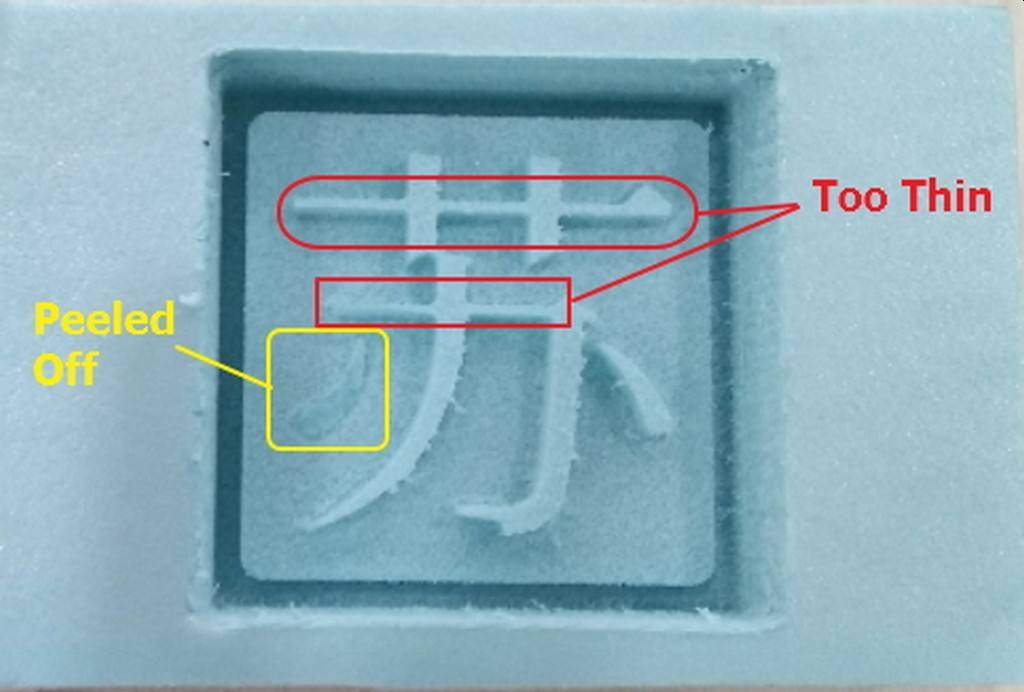
Image from 2017 Student Soh Hong Guan's page
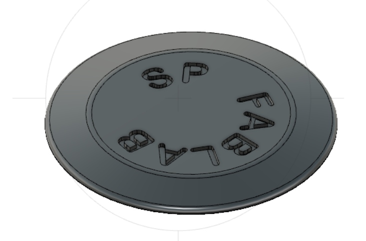
With these background information, I started to use Fusion 360 to design my positive mold. I decided to design a simple holder for a tea candle.

Image of a common tea candle
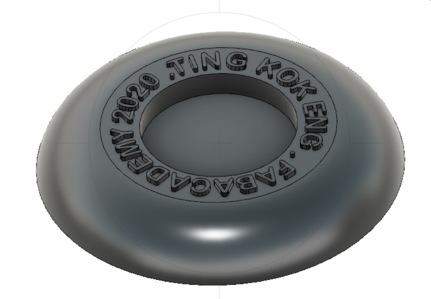
For the circular text, I used Inkscape to create a SVG and import it into Fusion 360.
Click Here to download the SVG file for the circular text.
Click Here to download the candle holder Fusion 360 file.
Before moving to the next stage which is to generate the tool path, I suddenly remembered that the smallest cutting bit is 2mm, it is hence impossible to mill out the wording properly, I decided to abort this design and made a simple pencil holder that will also requires 3-axis milling. The design is as follows:
Click Here to download the pencil holder Fusion 360 file.Part 2: Tool Path Generation & Milling the mold
To generate the tool path, I referred to the video tutorial by Lar Christensen titled Fusion 360 CAM Tutorial— 3D Machining- Basic. Lar Christensen recommends that the first step is to select the milling tool and do a preliminary toolpath preview. The steps are summarised in the image below:
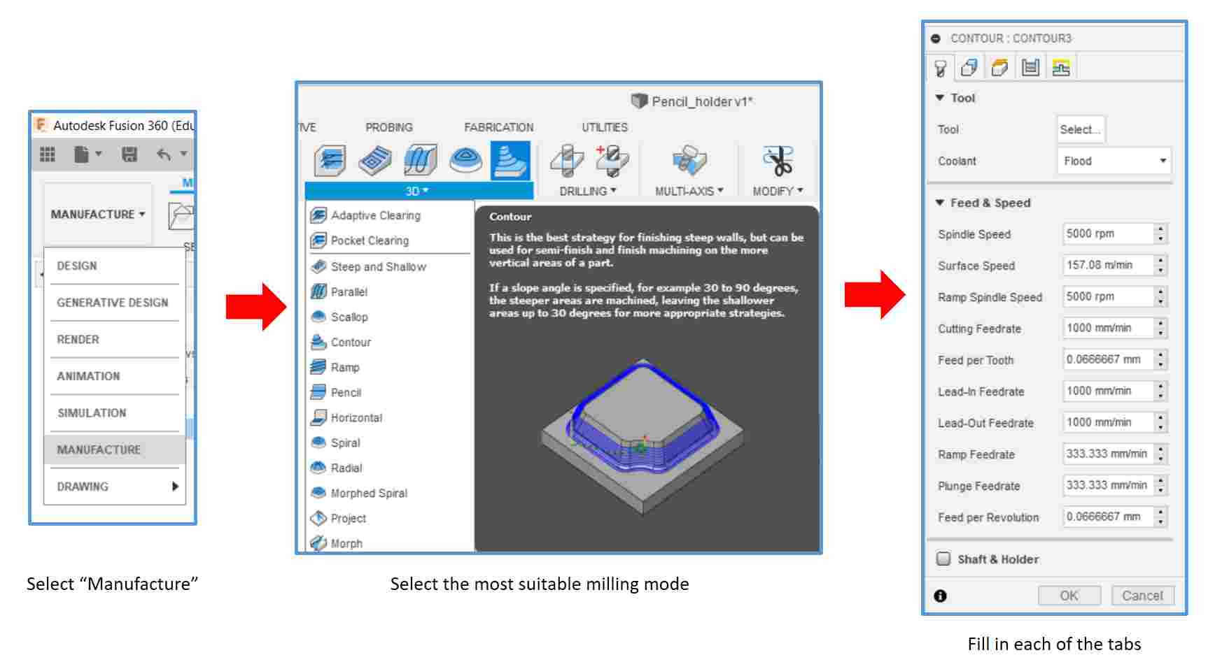
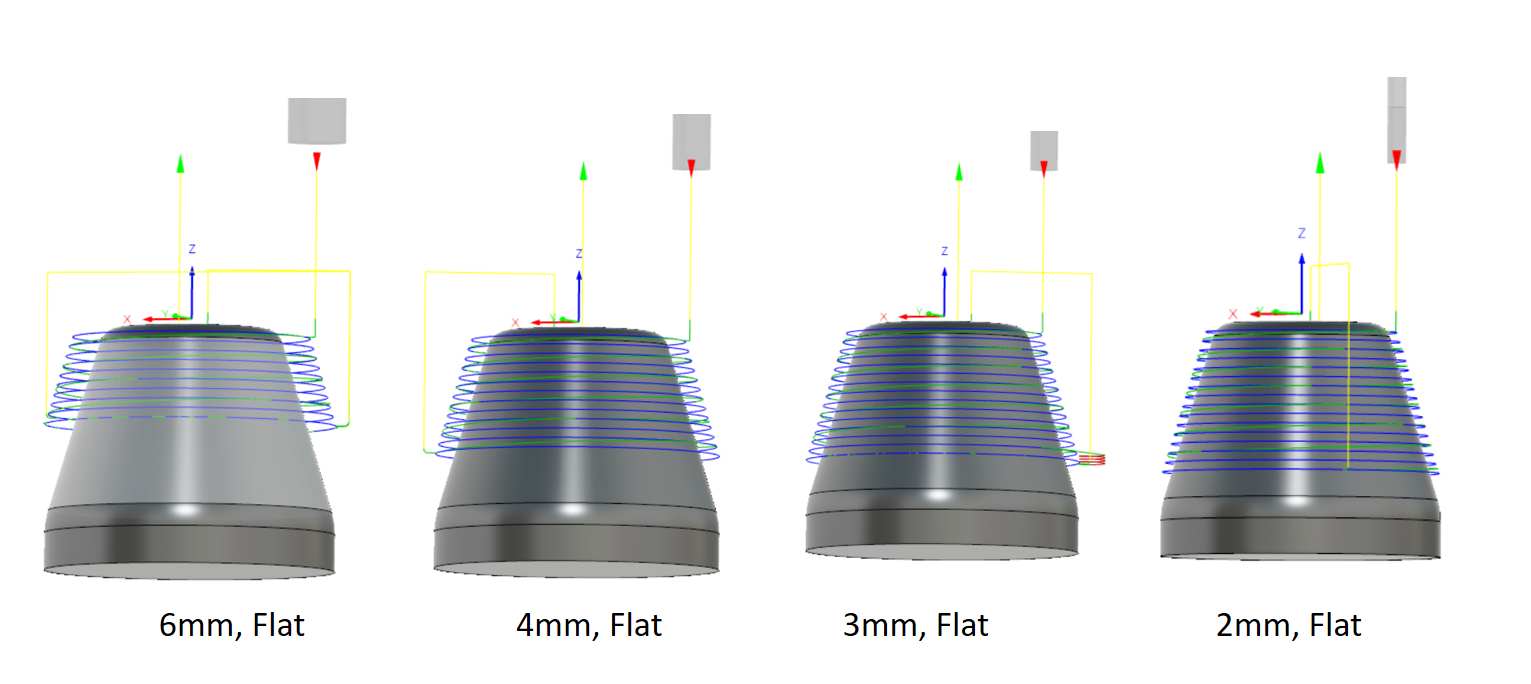
When selecting the tools, I tried 2mm, 3mm, 4mm and 6mm flat-end mills and used the "Contour" milling mode to generate the preliminary toolpath. I realised that for all the cutting bits, only the upper part of the model can be milled. The design is apparently too tall for the short flat end mill.
The next thing I tried was to use 2mm flat-end mill with different milling modes, namely Contour, Scallop, Parallel and Steep and Shallow. The toolpaths for all the milling modes again showed that the model cannot be properly milled.
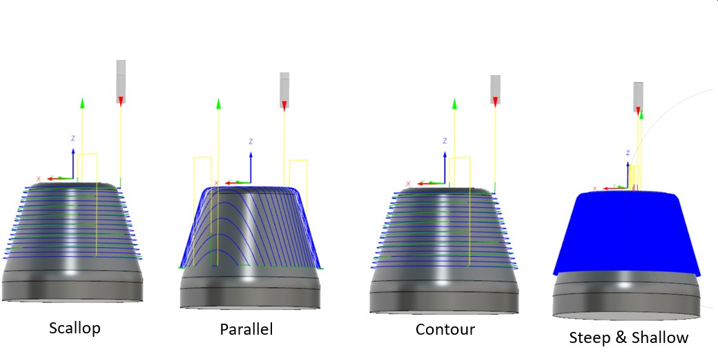
A new design is needed!
New design
As the assignment is about 3-axis milling, I decided to make something really simple. This is the new design, a coaster for cup.
Using 2mm Flat-end mill with Parallel milling mold, the preliminary toolpath is successfully generated.
Acceptable Toolpath
With the design issue settled, generating the toolpath can continue. Referring to the dialogue box below, after selecting the milling tool, the subsequent steps are to check and when necessary, modify the settings for the next 4 tabs, namely Geometry, Height, Passes and Linking.
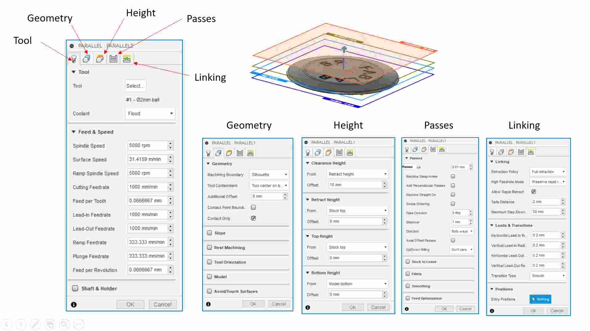
Once this is done, the final step is to generate the gcode (*.nc) file
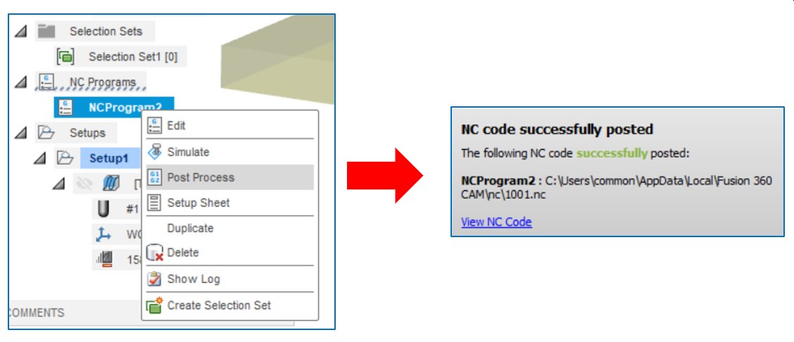
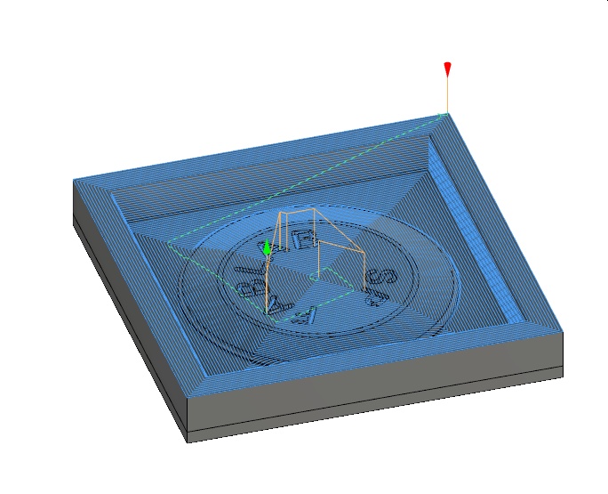
Fusion 360 also allows the user to view the simulation of the milling process. An example is shown below.
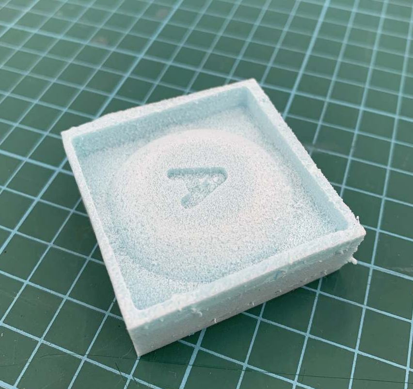
Click Here to download the gcode (*.nc) fileInitially I planned to construction the mold using 4 pieces of ice-cream sticks and heat glue, however, Prof Neil pointed out that the learning objective is to design, make and use the mold to do casting. I hence modified the design to include the mold. The rest of the process are the same as above. Below is the image of the coaster inside a mold.
Part 2: Making the Mold Using 3-Axis Milling
The original plan is to use the Roland Modela ProII MDX-540 desktop CNC machine to make the mold, however due to prolong closure of SP Fablab due to Covid-19, the machine components were dissemblted for storage and is unavailable for used. After discussing with our local coach, we decided to use the StepCraft 420 that we have used for the electronics production assignment.
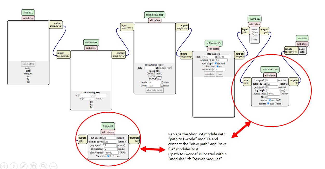
This change means that the gcode generated earlier cannot be used and needs to be regenerated. I decided to try a different approach - using mods. The steps are quite similar as loading the program for 2-D milling of SVG files for electronics production. The steps are summarised in the image below:
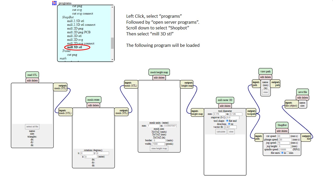
After loading the program, the next thing is to change the output as I am not using the ShopBot milling machine. To do this, I have to modify the program by deleting the ShopBot default modules and add in the generic ones. The steps are again summarised in the image below:
After making the changes, I can load the STL file of my coaster to generate the g-code and start the milling. The setup of the StepCraft 420 for milling the foam is similar to that for milling PCB and hence not documented here. For the milling, the following conditions were used, for the rest, the default machine settings were used.
- 3-mm flat-end mill
- Stepover - 0.5 times tool diameter
- Spindle speed 10000 rpm
- Cut Speed 250 mm/s
- plunge speed 250 mm/s
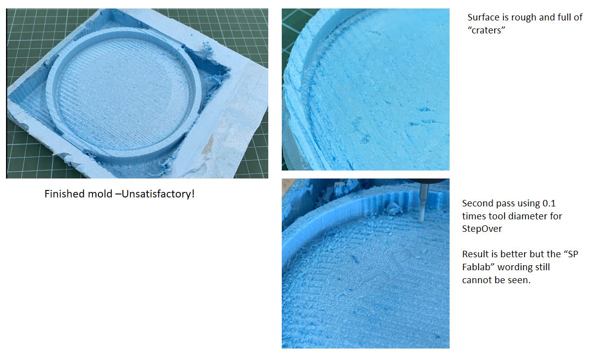
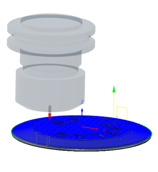
The outcome of the milling is unsatisfactory and I decided to mill another one using a different tool and settings. However as the milling for this design takes more than 4 hours and my coursemates need to use the machine as well, I decided to change the design to something smaller. The new design is a small button as shown in the image below
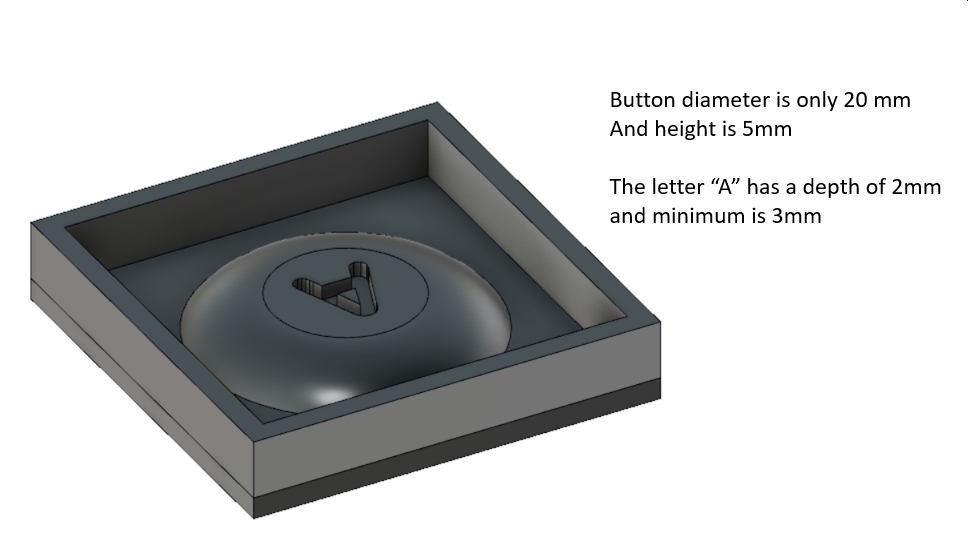
The file is available for downloading from autodesk.com cloud.
Using mods, the gcode for the tool path is generated. I then run Camotics to simulate the milling process to ensure that the letter "A" can be milled
Click Here to download the gcode *.nc file.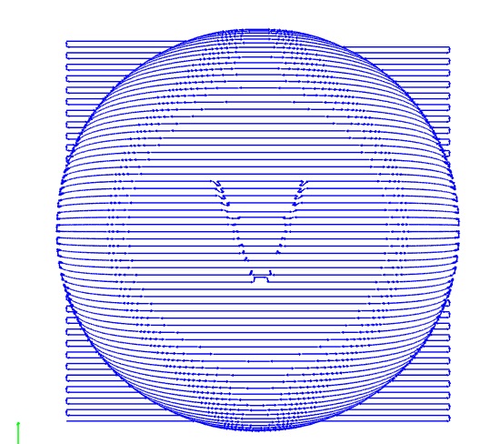
I milled this design using the following settings and the result is now satisfactory for the molding
- 2-mm flat-end mill
- Stepover - 0.1 times tool diameter
- Spindle speed 10000 rpm
- Cut Speed 250 mm/s
- plunge speed 250 mm/s
Part 3: Molding Process
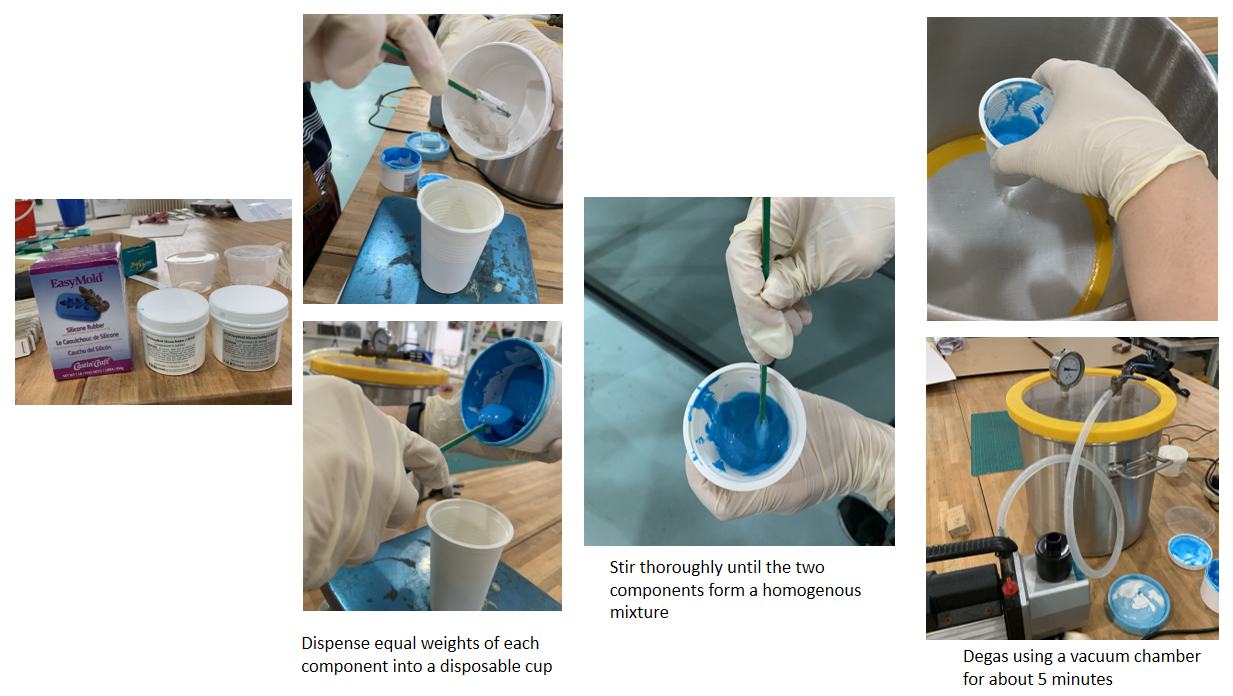
For the mold, our team used the EasyMold Silicone Rubber. The molding mixture is prepared by mixing equal weights of each component and stir thoroughly. It was noted that the molding mixture was unusually viscous, the team suspected that the chemicals may have deteriorated by nevertheless decided to go ahead and used it. As it is usually viscous, degassing using the vacuum chamber was performed. According to the product documentation, degassing is not required for EasyMold. The steps are summarised in the image below.
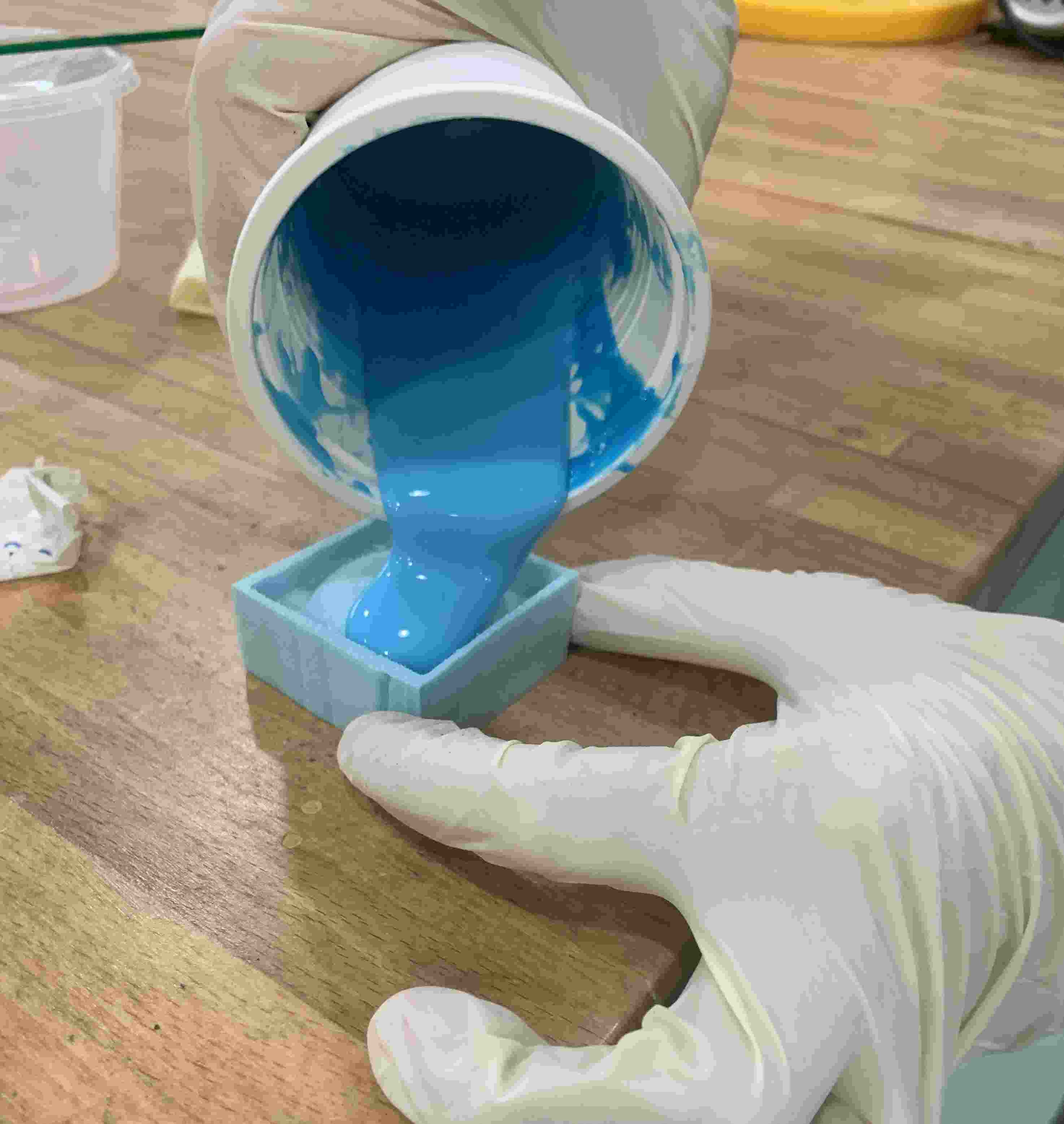
After degassing, the molding mixture can be pour carefully into the mold and allowed to dry overnight.
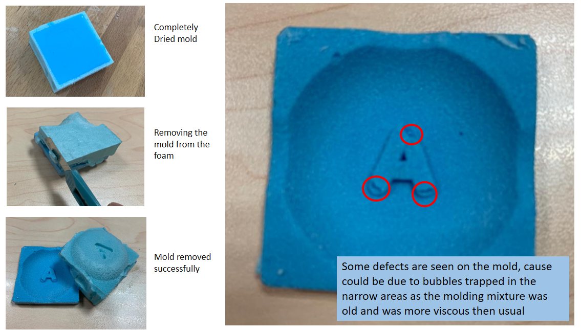
After more than 24 hours, the mold can be removed from the foam. Several defects were noted and it was believed to be due to air bubble trapped. Although not perfect, I am happy that it still looks good.
Part 4: Casting Process
For casting, I tried 3 compounds, namely: Beeswax, Parrafin Wax and Casting Epoxy (Epicote 1003). Epicote 1003 is a low-volatility epoxy resin.
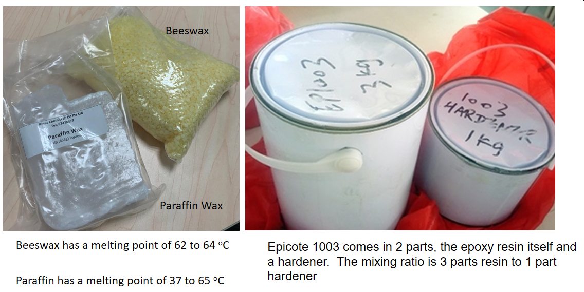
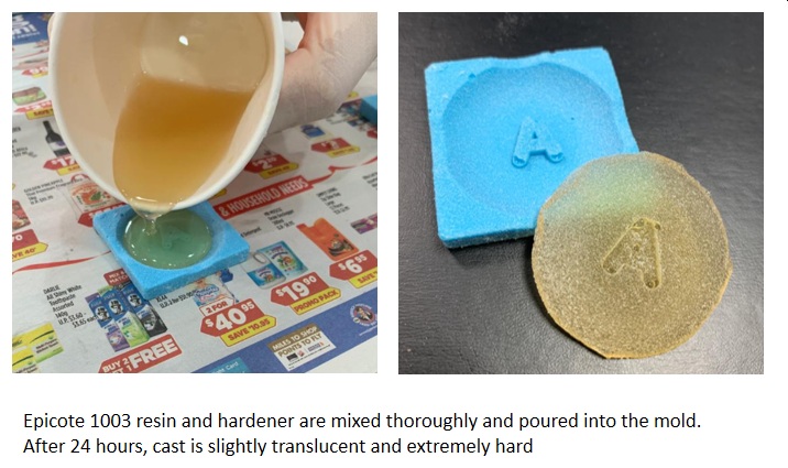
Casting with Epicote 1003
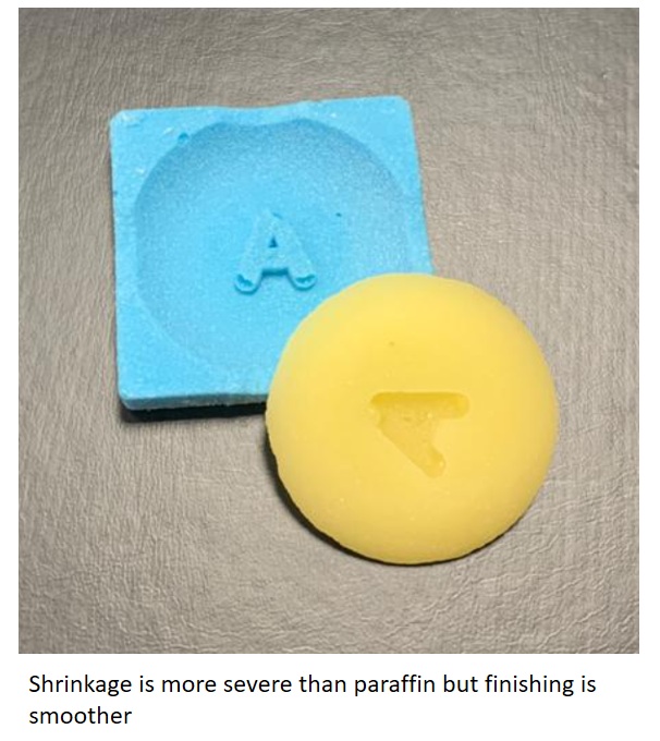
For the other two materials: paraffin wax and beeswax, they are simply heated on a hotplate until they melt completely. The molten wax is then poured into the silicone mold and left to harden.
Casting with Paraffin
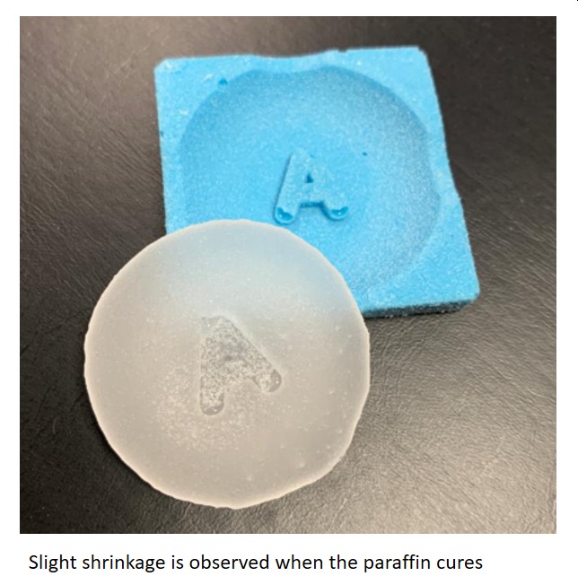
Casting with Paraffin
Lessons Learnt
- It is very important to consider at the design stage how the parts is to be manufactured. (i.e. Design for manufacturing)
- Cavities that are too small will trap air pockets resulting in imperfect cast