Exercise 14 - Networking and Communications7/5/2020 to 13/5/2020
There are 2 tasks for this week:
- Individual Assignment:: design, build, and connect wired or wireless node(s) with network or bus addresses
- Group Assignment:: Send a message between two projects
The group assignment is done with Noel Kristian, Yeo Gau Siong and Lucas Lim.
Due to Covid-19 situation, we are all working from home (WFH), hence we decided to study the different communication protols such as I2C, SPI, UART and Bluetooth BLE that are used for communications between electronic devices using Arduino UNO boards for our group assignment.
Our collective work is documented on the SP Fablab Website
.Individual Assignment
Part 1: Arduino-to-Arduino
In the Output Device assignment, I have tried to light up a LCD using the I2C (Inter-Integrated Circuit) protocol with an Arduino UNO board. Thus the first thing I want to try is to try use I2C to communicate between two Arduino boards with one acting as the MASTER and the other acts as a SLAVE. I followed the tutorial by Piyush K Singh in Arduico Project Hub. For this simple tutorial, only VCC, GND, pins A4 and A5 are used. The A4 and A5 pins on one Arduino UNO board are connected to the same pins on the other UNO board using dupont wires. For this tutorial, the Piyush's Sketch program on the Master will command the Slave Arduino to blink its built-in LED once or twice depending on the received value. Below is a video clip of the test I tried
.In the above example, the Master program has a counter that counts to 5 and rests to 0, the count is continuously transmitted to the Slave board. The slave will blink rapidly when the count value received is "0" and slowly when the count value is "5". To truly use the Master board to control the Slave board, I created another set of Sketch codes as follows:
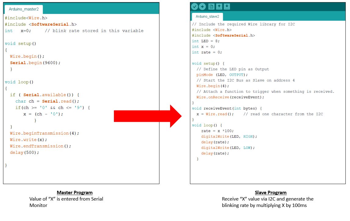
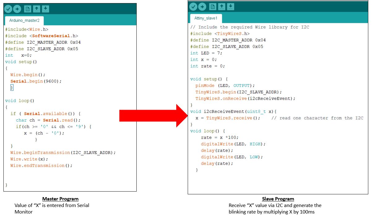
For this program, a value between 0 and 9 is entered into the serial monitor of the Master Arduino board. This value is transmitted via I2C to the Slave board. The value is multiplied by 100 milliseconds to give the LED blinking rate. In the video, a value of "1" was first entered, this made the LED on the Slave board blinks rapidly. Next a value of 9 was enetered and the LED blinks slowly.
Part 2: Arduino-to-ATtiny
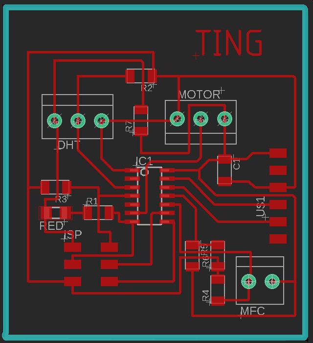
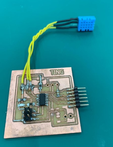
As SP Fablab is closed due to Covid-19 and we are working from home. I have limited components and equipment to work on. My Hello board is soemhow dead and cannot be used. Out of desperatiuon, I turned to my ATtiny44 board that I made for my Input Devices assignment. For that assignment, I have designed a board using ATtiny44 with 3 pull-ups to cater to a humidity meter, a motor and the microbial fuelcell. Although working, I have decided to discard this board as the memory for ATtiny44 is too small and SP Fablab does not have ATtiny 84. In addition, there were also a few mistakes on it such as unavailablility of header pin, which that made it unsuitable for use in my final project. The board layout and image of the partially stuffed board is as below.
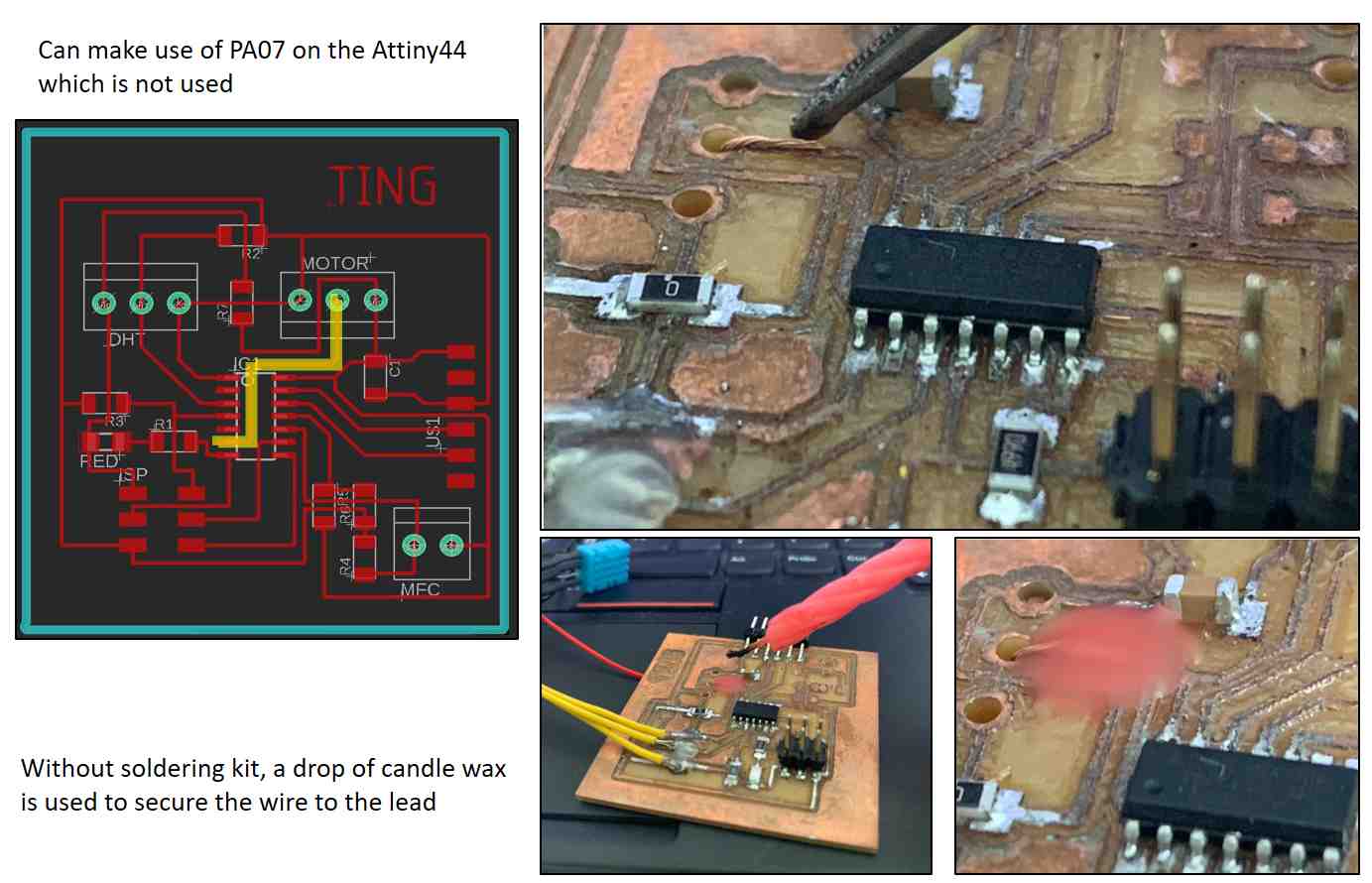
I decided to make improvision to board so that it can be used of the assignment this week. I passed a piece of wire though the centre terminal hole and secured it with a drop of candle wax (which is what I can fins at home). I then connect this wire to a 570 Ω resistor and a red LED. With this improvision, I can continue with my assignment. In hindsight, I could have simply connect the LED to my FDTI pins since I am not going to use the TX and RX pins for this assignment.
Using ATtiny44 board as the Slave
As I only have one working ATtiny44 board, I have to use Ardunio UNO board as my Master board and the ATtiny as the Slave board. For this exercise I referred to WanderingEngineer.com website as a guide. As ATtiny44 only has 4 Kb of memory, the TinyWireS.h library must be used instead of the Wire.h library. The TinyWireS.h (S denotes Slave) can be downloaded from Rambo Github site.
Using the tutorials on Arduino ProjectHub and theWanderingEngineer.com as guides, I modified the slave sketch program while keeping the sketch file for the master the same. The alogrithm is the same as Part 1 when two Arduino boards are used.
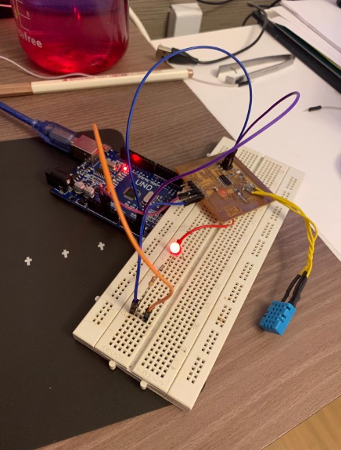
Both sketch programs can be compiled and loaded to the UNO and ATtiny44 boards. For the ATtiny44, the SDA and SCL are tapped from the ISP header and connected to A4 and A5 on the Arduino UNO board. However, the program failed to run unlike above. The LED stay lit all the time and does not response to input in the serial monitor of the UNO board. The value of X is somehow not received by the slave board. Below is an image of the setup.
After consulting my coach, Steven, I decided to try running Steven's program using UNO as Master and my Attiny44 as the Slave board. Steven's program is as below:
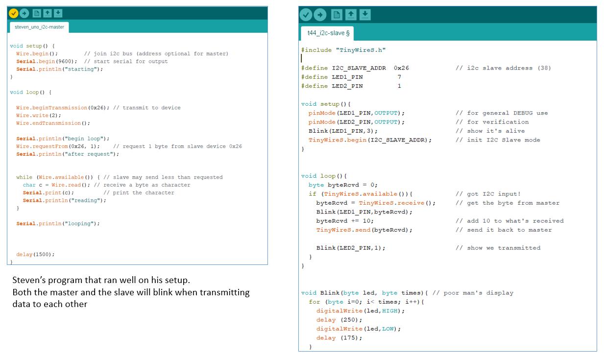
My setup however, failed to function as expected, referring to the video clip on the left, the Serial Monitor of the UNO board can run when the SDA and SCL cables are not connected to the ATtiny44 board but once the cables are connected, the serial monitor froze. When just powered, the LED blinks 3 times, as per the "void setup()" in the Sketch program, indicating that the program is properly uploaded into the ATtiny44 board. I suspected there could be some issues with my board, since the program can run properly on my coach's setup. As I do not have proper equipment to even check for continuity nor do I have another circuit board to test, I decided to abort further testing until I can have access to SP Fablab. I plan to make a new board to complete this assignment.
Video from my coach, Steven showing how the program should operate
Updates
For the final project, I made a new board using ATmega 328. I connected the HC-04 Bluetooth BLE module to the TX and RX pins (Pin 1 and Pin 0) and used it to transmit voltage reading from the potentiometer to an Android smartphone. An APP written using MIT App Inventor was created to read the voltage reading. More information is available on the final project page
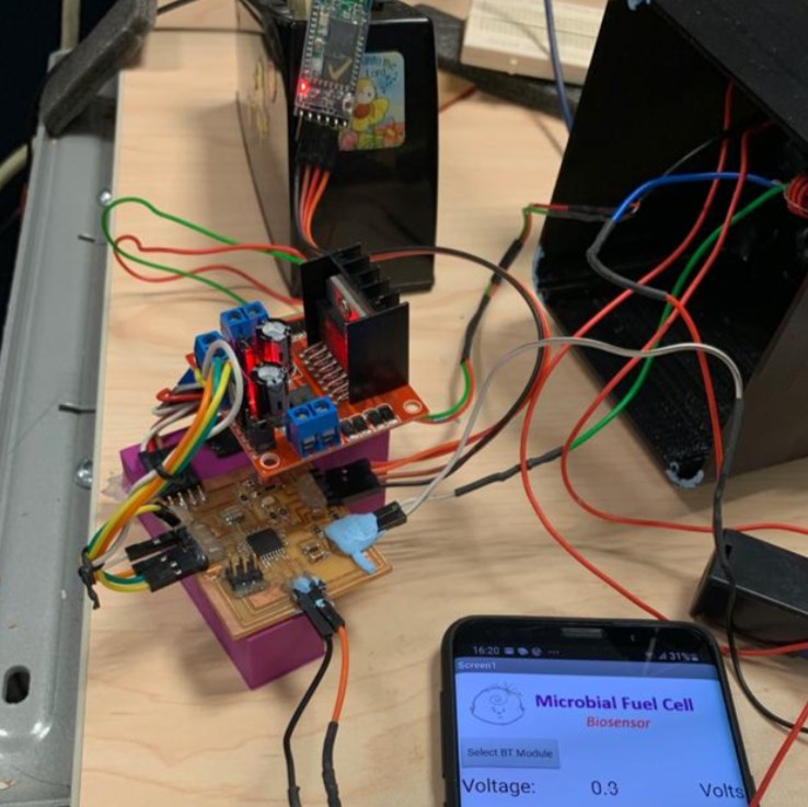
The video below shows data being transmitted via bluetooth to the smartphone
Final Test