Exercise 12 - Interface and Application Programming23/4/2020 to 29/4/2020
There are 2 tasks for this week:
- Individual Assignment: Write an application that interfaces a user with an input and/or output device that you have made.
- Group Assignment: Compare as many tool options as possible.
The group assignment is done with Noel Kristian, Yeo Gau Siong and Lucas Lim.
Our collective work is documented on the SP Fablab Website
✨Individual Assignment✨
Similar to last week's assignment, with the closure of SP Fablab due to Covid-19, the assignment can only be completed using the Arduino UNO board with sensors and electronic components that I managed to bring home.
For this assignment, I carried out 2 studies, namely:
- Use Laptop running Python to control the Ardunio pin
- Use Laptop running Python to capture and process data from a sensor on an Arduino UNO board.
(1) Python-To-Arduino
For this study, my aim is to write a program in python to control an ardunio pin using a graphic user interface (GUI). My learning journey can be divided into several phases, as below:
(A) Acquire basic knowledge on Python programming. Being completely new to programming (the last time I touch programming was almost 3 decades ago and it was Fortran 77!), I watched several tutorial videos on Youtube. One trainer that I particularly like is YK from CS Dojo.
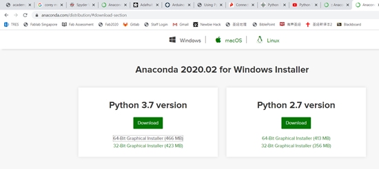
(B) Install softwares. I do not need to install Python as my laptop pre-installed with Python verson 3.8. Following the training videos, I installed Anancoda , for Python 3.7, which is a package manager.
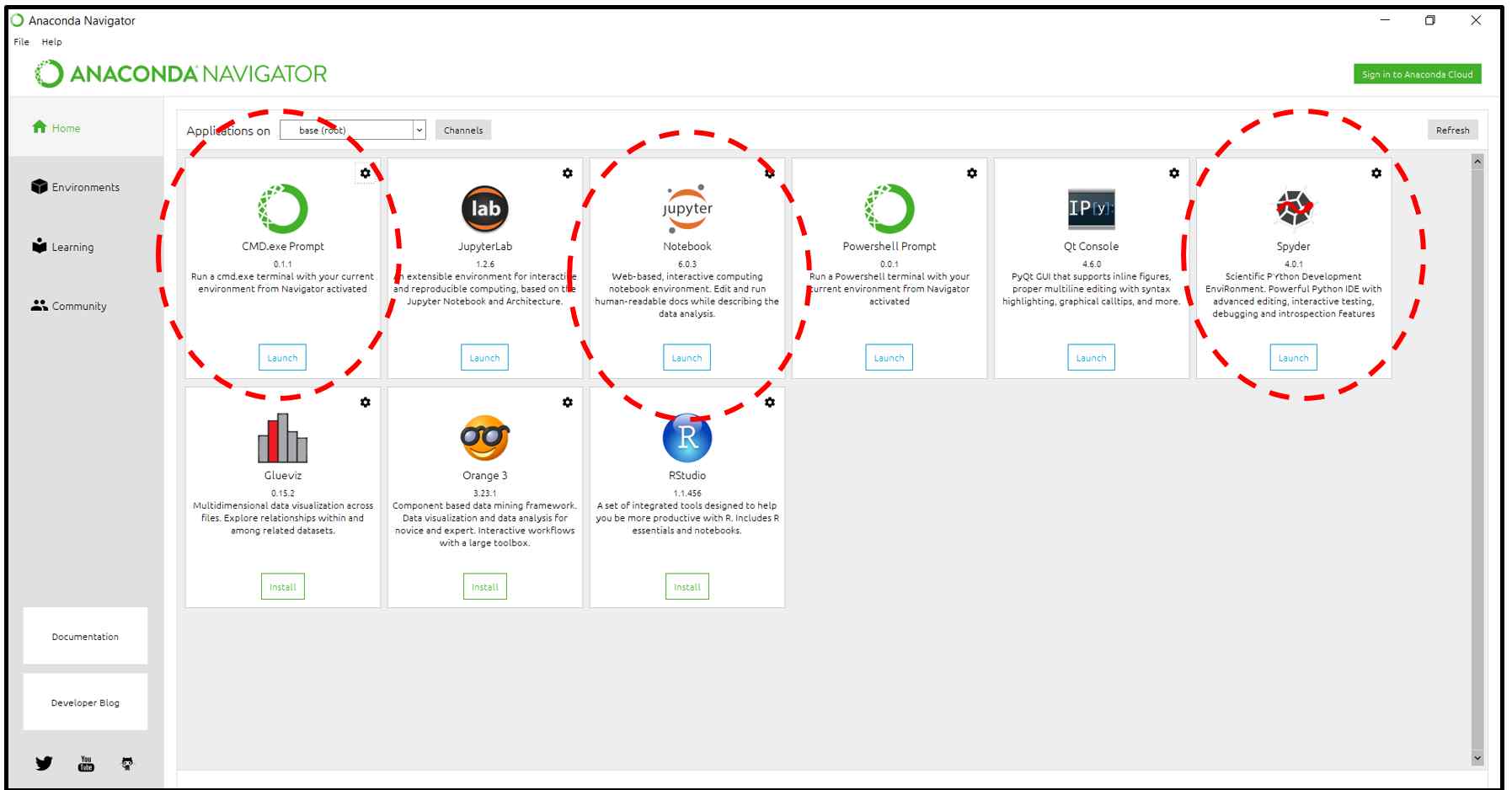
After installation, I launched the anaconda navigator that provides a convenient interface for me to assess other programs such as Jupter Notebook and Sypder.
(C) Circuit Setup and writing Ardunio Sketch program. Since this is my first attempt at coding, to avoid complication in debugging, I build a simple circuit on Arduino UNO board with only one red LED and a 220-Ω (the only small resistor I can find at home). The photo and the Sketch program are as below. I modified the Sketch program from the youtube video by MonkHaus

to download the Arduino Sketch file.
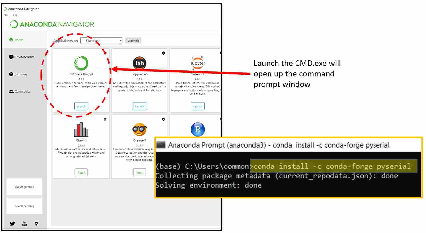
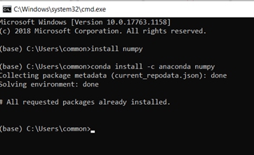
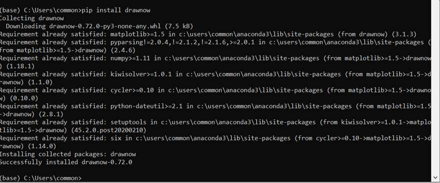
(D) Coding Python Program. In order for the python program to communicate with the Arduino serial port, the module pyserial must first be installed. Since I have installed Anaconda package manager, installing this is easily done through the command prompt.
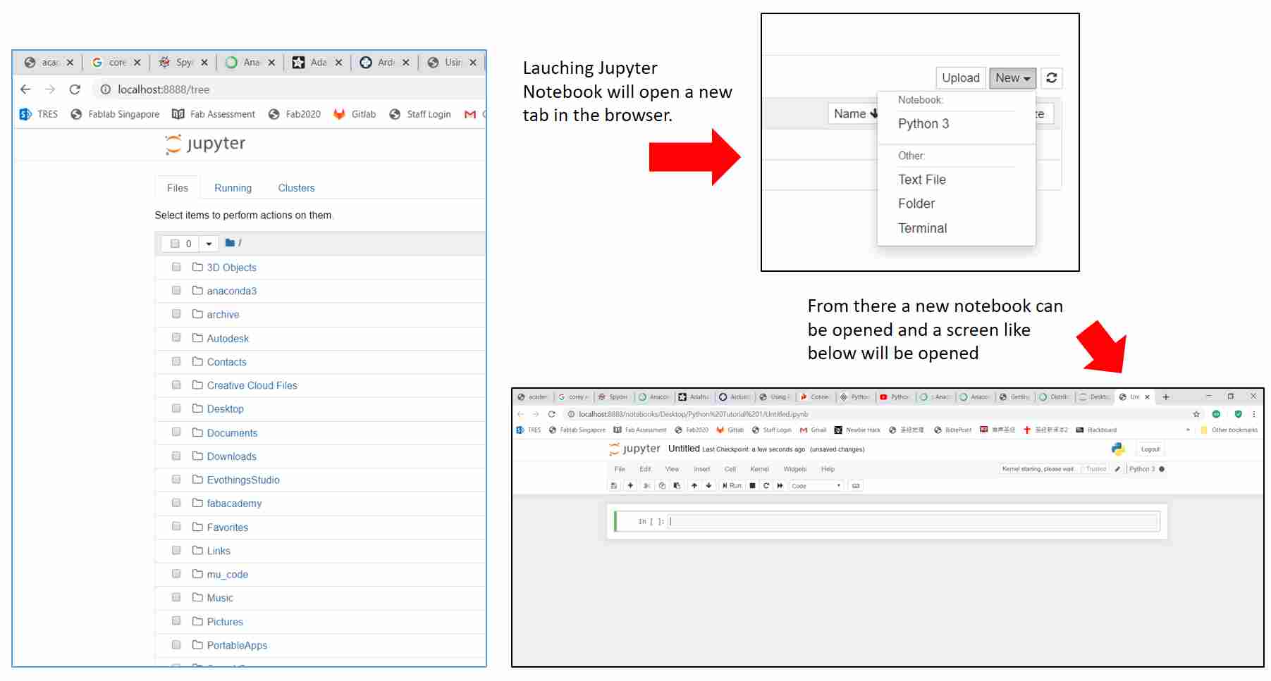
After installing the pyserial module, I can start the python coding using Jupyter Notebook as it allows me to run my code line by line.
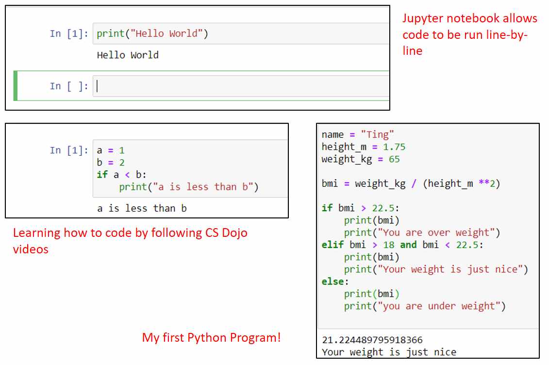
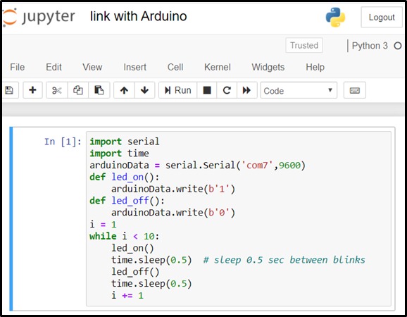
Below is the python code I wrote and a short video clip of the circuit in operation. When run, it will send a command to the Arduino UNO board to turn on the LED 9 times.
Having successfully use python program from the laptop to control an Arduino pin, the next task is to design a graphic user interface (GUI). For this, I again watched several training videos and eventually decided to use Tkinter.
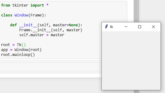
Tkinter is a standard library in python which allows the user to easily create windows and graphical user interfaces. Following the training video of Tkinter website. I was able to effortlessly create a very basic window in just 8 lines which can be resize, minimize, maximize, and close.
The next step is to create a button which I can used to run the python program I wrote earlier for turning on the LED. Below is the new python code as well as the video showing the window with the button.
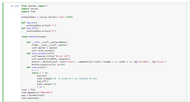
In this video, when the Run button is clicked, a window with a purple button will appear. Pressing the button with blink the LED 9 times.
This completes the study to use python to control an Arduino pin using a GUI
to download the python file.
(2) Arduino-To-Python
In the study above, I attempted to use python to send a command to Arduino. In this study, I tried to code in python to receive data from Arduino to my laptop. The approach is similar to the study above. As the first 2 steps are already completed, I proceeded immediately to the third step.
(A) Circuit Setup and writing Ardunio Sketch program.
For this exercise, I setup the ultrasonic sensor to measure the distance and send the data via the serial plot. I used the Sketch program that my teammate Noel has coded for our group assignment for the Input Devices lesson.
The arduino sketch program can be downloaded from Noel's page. For the Python programs, I followed the video tutorial from WaveShapePlay closely and was able to quickly collect the data from the Arduino board.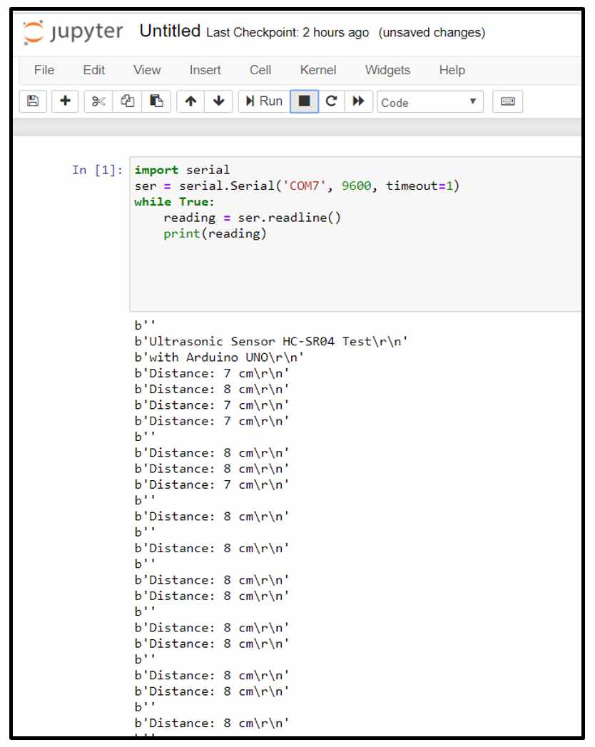
Being able to capture the data from the Arduino board to my laptop using python, the next step is to present that data in graphical form. As I am unfamiliar with the ultrasonic sketch program, I decided to follow the article from the Problem Solving With Python website. I built a simple voltage divider circuit using a 10 KΩ potentiometer to generate analog signals instead of using the ultrasonic sensor for simplicity. When the potentiometer is turned, the corresponding voltage will be sent as an analog signal from Pin A0 via the serial port to the laptop. I added a red LED and a 220-Ω resistor to check that the circuit is working properly. The LED will light up when the resistance is more than 5 KΩ. The setup and the Arduino Sketch program are as below:
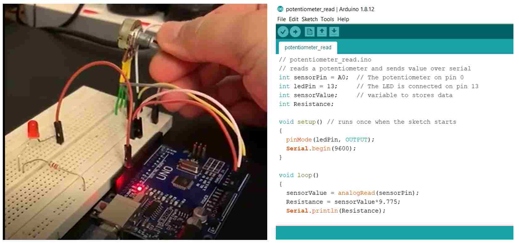
to download the Arduino Sketch file.
For the python program, I used Matpoltlib to my realtime graph. I installed the matplotlib modules using Ananconda in the same way as I did for pyserial. Using the article as a guide, I managed to code and run my python program. The code however was only able to collect the data first and thereafter plot the data into a resistance-time graph. This is not what I plan to achieve.
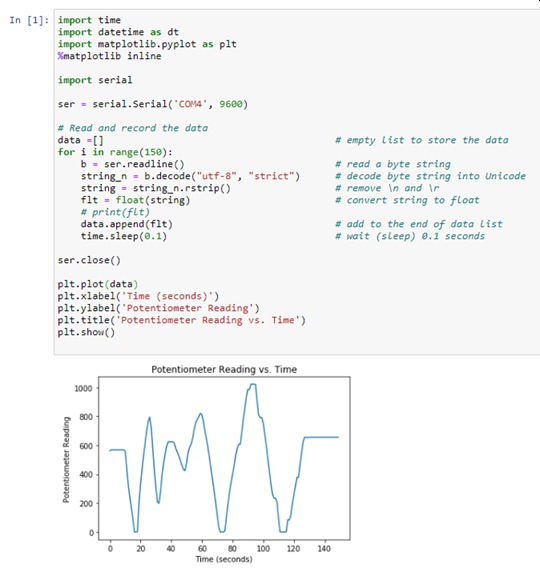
to download the python file.
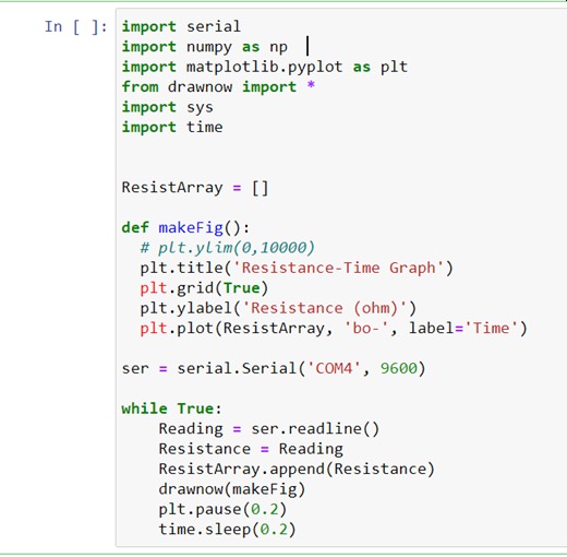
To display the chart in real-time as the data comes in, I watched the video by Corey Schafer to learn how to code. To display the chart in realtime, I installed another 2 modules in python, namely numpy and drawnow.
After installing these modules, I managed to get the program to display the chart in real time. The python program and the video are as follows:
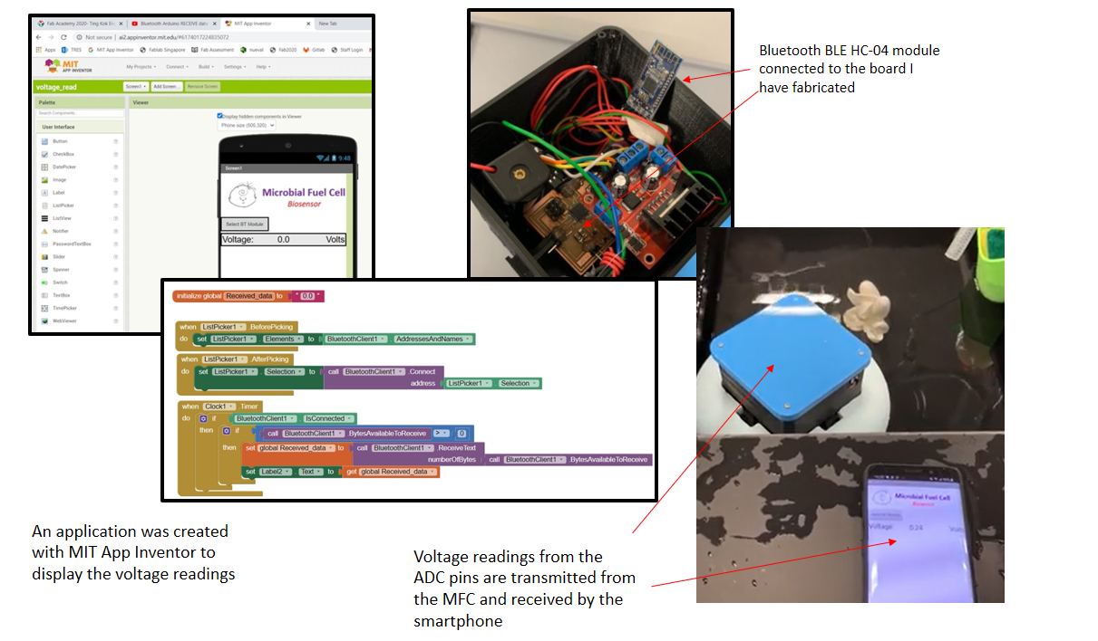
This completes the assignment for this week. For the requirement of writing an application that interfaces a user with an input and/or output device that I have made, I have decided to use MIT App inventor to create an App to receive and display data from my MFC (Input device) when SP Fablab is opened.
to download the python file.
Updates
SP Fablab was opened from 8 Jun 2020 and I managed to fabricate a board using ATmega 328 chip. I connected HC-04 bluetooth BLE board to this board and used it to transmit voltage readings from the ADC pins to a smart phone. For the Smartphone, I used MIT App Inventor to create an application to display the voltage.
More details are available from the following Final project pages: