Exercise 11 - Output Devices16/4/2020 to 22/4/2020
There are 2 tasks for this week:
- Individual Assignment: Add an output device to a microcontroller board that you have designed and program it to do something
- Group Assignment: Measure the power consumption of an output device.
The group assignment is done with Noel Kristian and Yeo Gau Siong.
Our collective work is documented on the SP Fablab Website
Individual Assignment
In week 9, I have designed and fabricated a microcontroller board that can be used for my final project. For this microcontroller, I planned to use ATtiny84 which has 8K of memory that should be sufficient for the final project requirement. However, I was told that SP Fablab does not have ATtiny84 hence I have to use ATtiny44 instead. With only 4K of memory, I encountered insufficient memory when trying to run just the DHT11 library. Since the microcontroller is to also control a DC motor, read the voltages from the biosensor and transmit the data via bluetooth, I decided to abandon this microcontroller board that I have built and make a new board using Atmega 328 chip instead.
As SP Fablab is closed due to COVID-19, I cannot fabricate a new board, hence the assignment for output devices is done using Ardunio UNO board which also uses the Atmega 328 chip.
For the output devices, I tested the following:
To have a basic understanding about stepper motor, I referred to Adafruit.com website. According to the website, stepper motors are DC motors that move in discrete steps. They have multiple coils and by energizing the each coil in sequence, the motor hence does not rotate but steps, one step at a time. Because of this, very precise positioning and/or speed control can be achieved with stepper motor.
For this assignment, a small 5V stepper motor (28BYJ-48) is used.
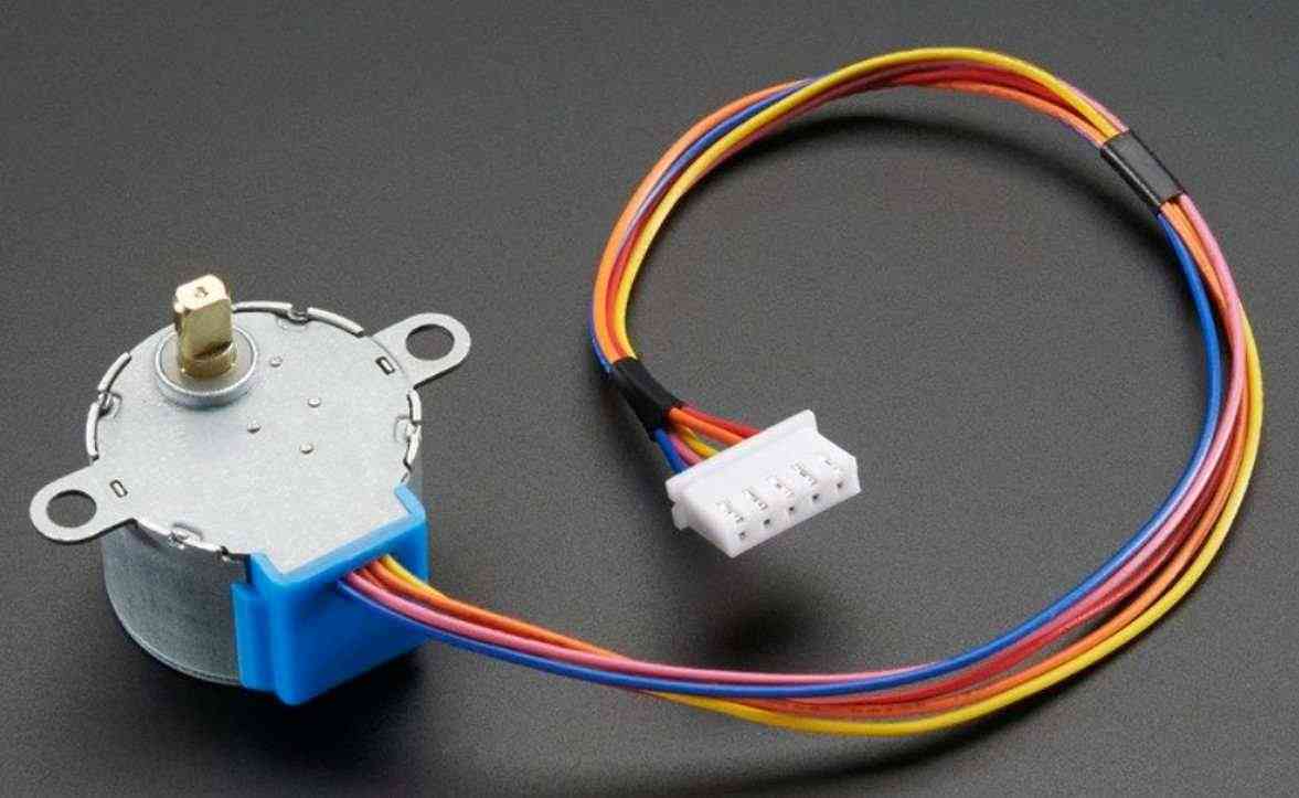
From Adafruit.com website again, this stepper motor is uni-polar and takes 32 steps to make one revolution (11.25 degree) per revolution which works out to be 11.25 degree per step. Due to the gearing inside, interleaved or micro-stepping should not be used to control the motor, single or double stepping is recommended. With a 5V supply, the recommended speed is under 25 RPM.
More information about the motor are as follows:
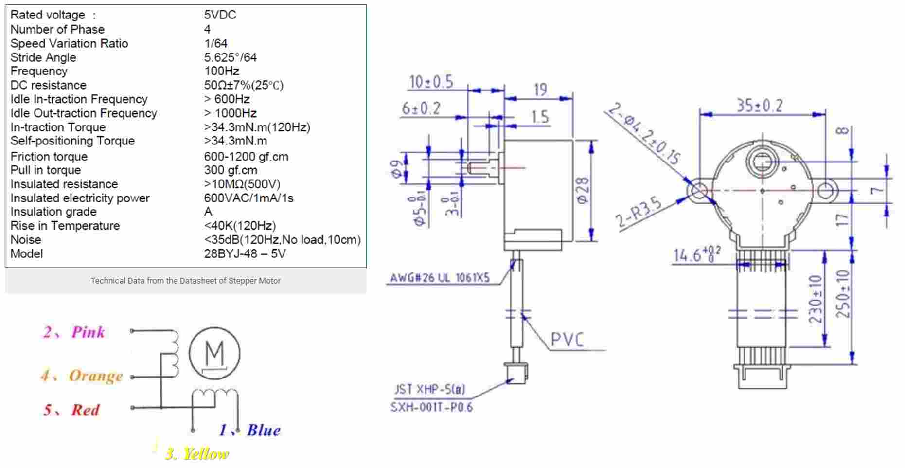
From the image above, the 28BYJ-48 stepper motor has 5 coloured wires. The red wire is the supply (5V, VCC) while the remaining four wires will be pulled to ground for triggering the respective coil. With a microcontroller, these four coils can be energized in a particular sequence to make the motor perform the required number of steps.
Although this motor requires only 5V, to drive it, a motor driver module is required as the controller module (in my case Arduino UNO) is not able to supply sufficient current from its I/O pins to operate the motor. For this assignment, the ULN2003 motor driver module is used.
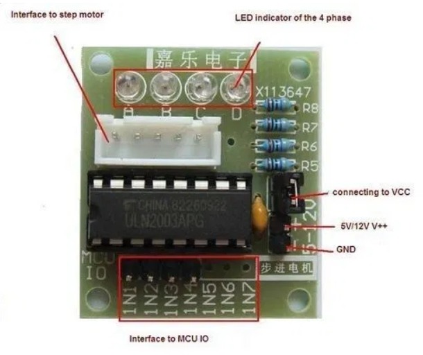
The workflow to operate the stepper motor using the Ardunio UNO board is as follows:
- Connect an external 5V supply to the ULN2003 driver module
- Connect the 28BYJ-48 stepper motor to the driver module
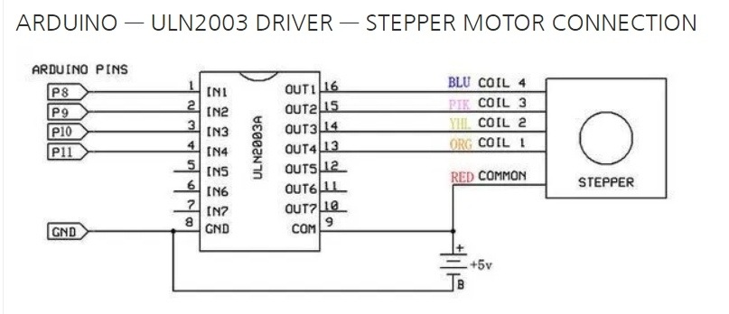
- Use Dupont wires to connect the driver module to Ardunio UNO board (refer to image below)
- Upload Sketch program to the UNO board to operate the stepper motor
Operating the stepper motor in Ardunio IDE is easy as it already contains a library called Stepper.h. Being new to programming, for the Sketch program, I followed the tutorial from Circuitdigest.com and used the ardunio Sketch program given in the tutorial. The program is as below:
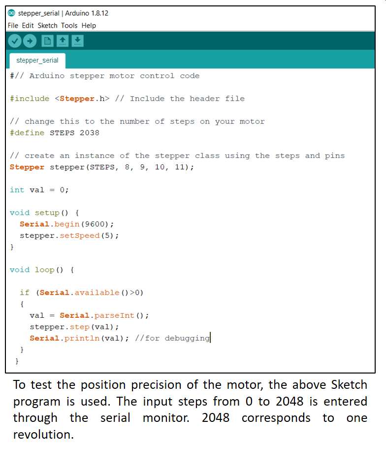
For this stepper motor, the number of steps per revolution is 32 and the gear ratio is 64, hence for one revolution, the value is 2048.
to download the Arduino Sketch files from Circuitdigest.com.My local coach, challenged me to operate this stepper with using the ardinuo stepper.h library. I will revisit this when I have completed my other output devices and the new board design using Atmega 328 chip.
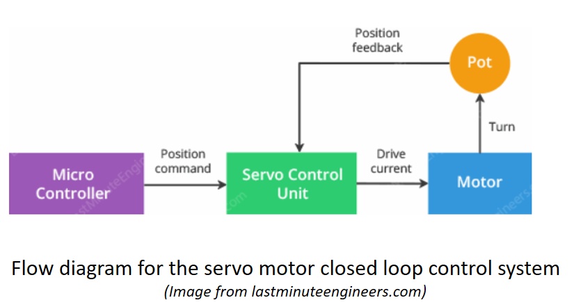
For servo motor, I referred to lastminuteengineers.com website to have a basic understanding for what a servo motor is, its characteristics and mode of operation. From the website, I learnt that a servo motor is actually made up of a simple high speed, low torque DC motor and a gear box that is connected to a potentiometer. The potentiometer provides position feedback to the servo control unit where the present position of the motor is compared to the target position. The control unit then moves the motor so that the actual position matches the target position. This is better explained using the flow diagram from the website
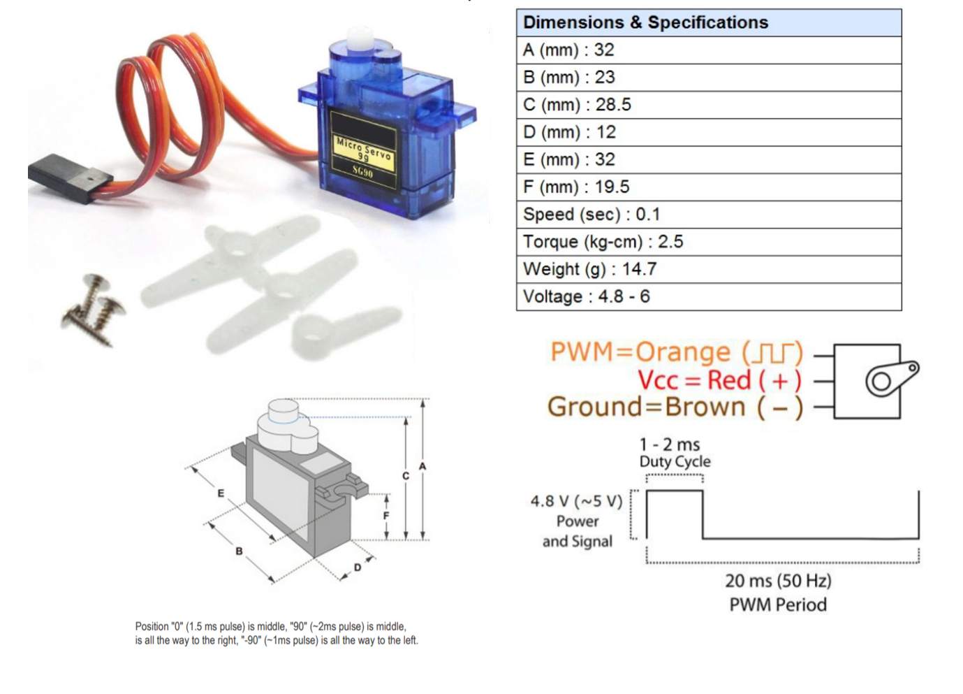
For this assignment, a 9-gram micro-servo motor (SG90) is used. This motor has 3 wires; namely supply, ground and control (PWM).
The workflow to operate the servo motor using the Ardunio UNO board is quite similar to the stepper and is as follows:
As this motor draws only around 100 to 250 mA during operation, I connected it directly to the Ardunio UNO board to power it.
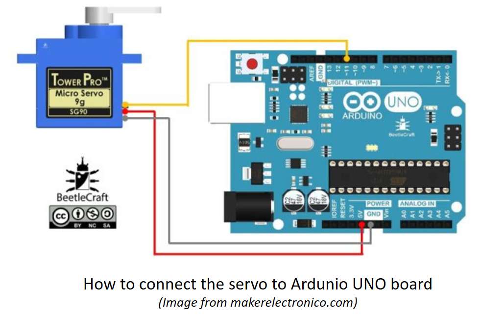
- Connect the red and black cables of the servo motor to the Ardunio board 5V and Ground using Dupont wires.
- Connect the orange cable using Dupont wires to the PWM pin (pin 9) on the Ardunio UNO board (refer to image below)
- Upload Sketch program to the UNO board to operate the servo motor
Like stepper motor, Ardunio has a library for servo motors. To use, simply include the line Servo.h at the first line of the sketch program.
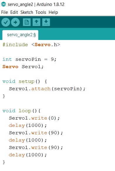
The Sketch program makes the motor turns 90 degree, pauses for 1 second, then turn another 90 degree, wait for 1 second then return to start position
3. DC Motors
From electronics-tutorials.ws, DC motors are commonly used actuator for producing continuous movement as their speeds of rotation can easily be controlled. For these motors, the speed of rotation is almost linearly related to the applied DC voltage while the output torques are determined by the current flowing through the motor windings.
The speed of rotation of any DC motor can be varied from a few revolutions per minute (rpm) to many thousands of revolutions per minute making them suitable for electronic, automotive or robotic applications. By connecting them to gearboxes, their output speeds can be decreased while the torque output can be increased.
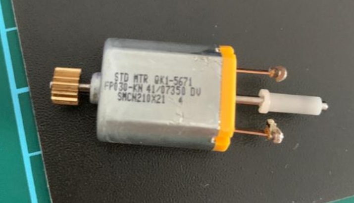
For this assignment, I used a small DC motor (image above) that I recovered from a spoilt Canon deskjet printer. It is a 4.5V motor but can operate when a 3V supply is used. Little information is available when a google research is done for this motor 9STD MTR QK1-5671), however I decided to proceed with this motor for learning and later moved to the water pump (brushless DC motor) which I will used for my final project.
In order to have control over the speed as well as the direction of the DC motor, the L298N motor driver controller board is used. To use this controller, I referred to lastminuteengineers.com. The tutorial on the website is very comprehensive. Below is a brief summary of my learning from the website.
(All images and diagrams are taken form the website)
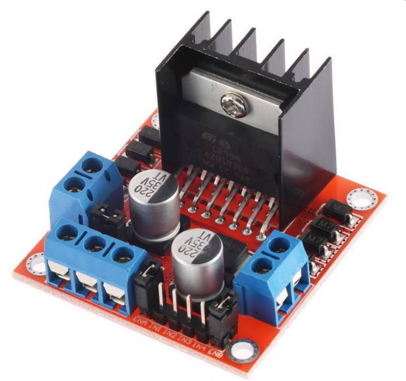
L298N is a H-bridge motor driver that can control 2 DC motors. The speed of a DC motor is controlled by varying the motor input voltage through the use pulse width modulation (PWM) while the direction of the motor is via the H-bridge. The L298N motor driver IC has two input power pins: Vss and Vs. The Vs pin supplies power to the H-Bridge to drive the motor, while the Vss is used for driving the logic circuitry.
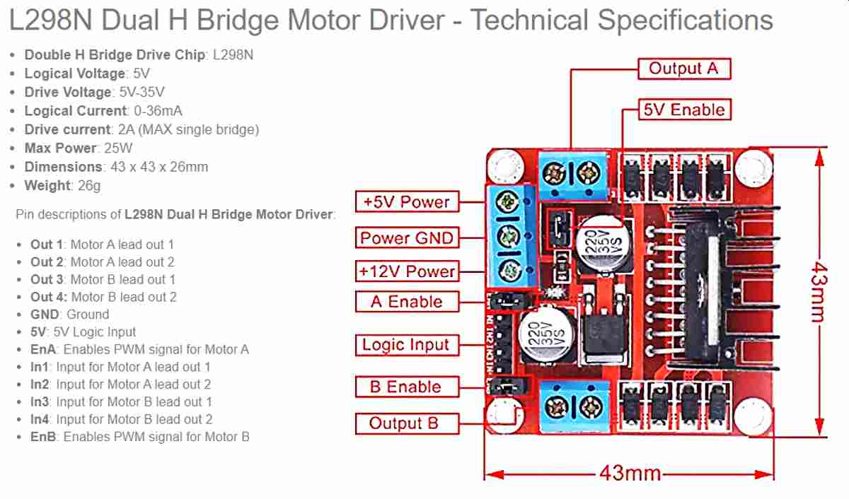
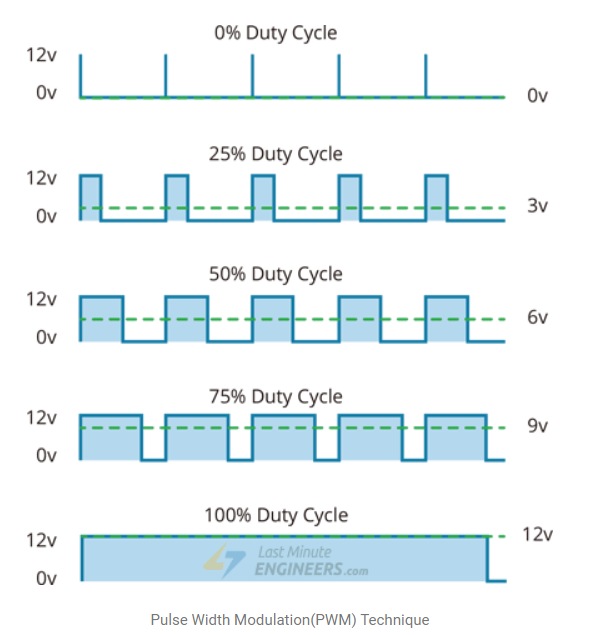
Motor speed is controlled using the ENA and ENB pins. To enable the use of these pins, the jumpers must be removed. When this jumper is in place, the motor spins at maximum speed when turns on. To control the motor speed, PWM is used. PWN is a technique where the average value of the input voltage is adjusted by sending a series of ON-OFF pulses. The average voltage is proportional to the width of the pulses known as Duty Cycle.
The higher the duty cycle, the greater the average voltage and the faster the motor will turn.
The workflow to operate the DC motor using the Ardunio UNO board is straight forward as follows:
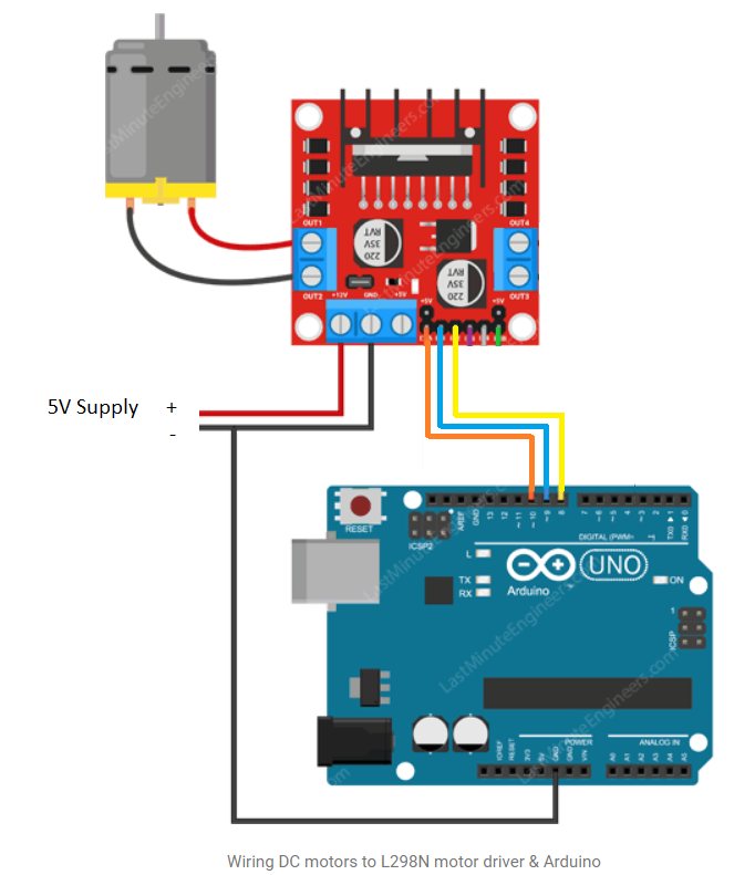
- Connect the power supply to L298N 5V and GND terminals. (As the input voltage is less than 12V, the jumper is in place which enable the 5V regulator. As such that the 5V supply can supply power for both the circuitry and the motor
- Connect the EnA, IN1 and IN2 pins using Dupont wires to the pins 10, 9 and 8 respectively on the Ardunio UNO board (refer to image below)
- Upload Sketch program to the UNO board to operate the servo motor
I tried two Ardunio sketch programs. In the first, only IN1 and IN2 are connected to Ardunio pin 9 and 8. This program allows me to understand about controlling the direction of spin. Below is a screen capture of the program as well as a video of the motor in operation.
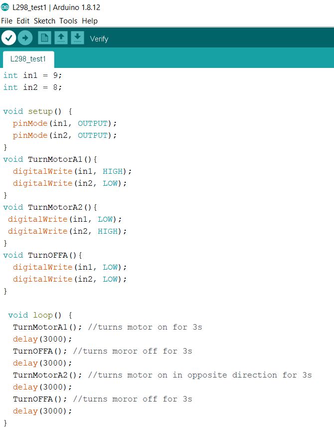
The Sketch program makes the motor spins for 3 seconds stop then spins in opposite direction for another 3 seconds.
The second program, is to learn how ro control the speed of the DC motor using PWM. The jumper at the EnA is removed and the pin is connected to Pin 10 on the Ardunio UNO board which is a PWM pin.
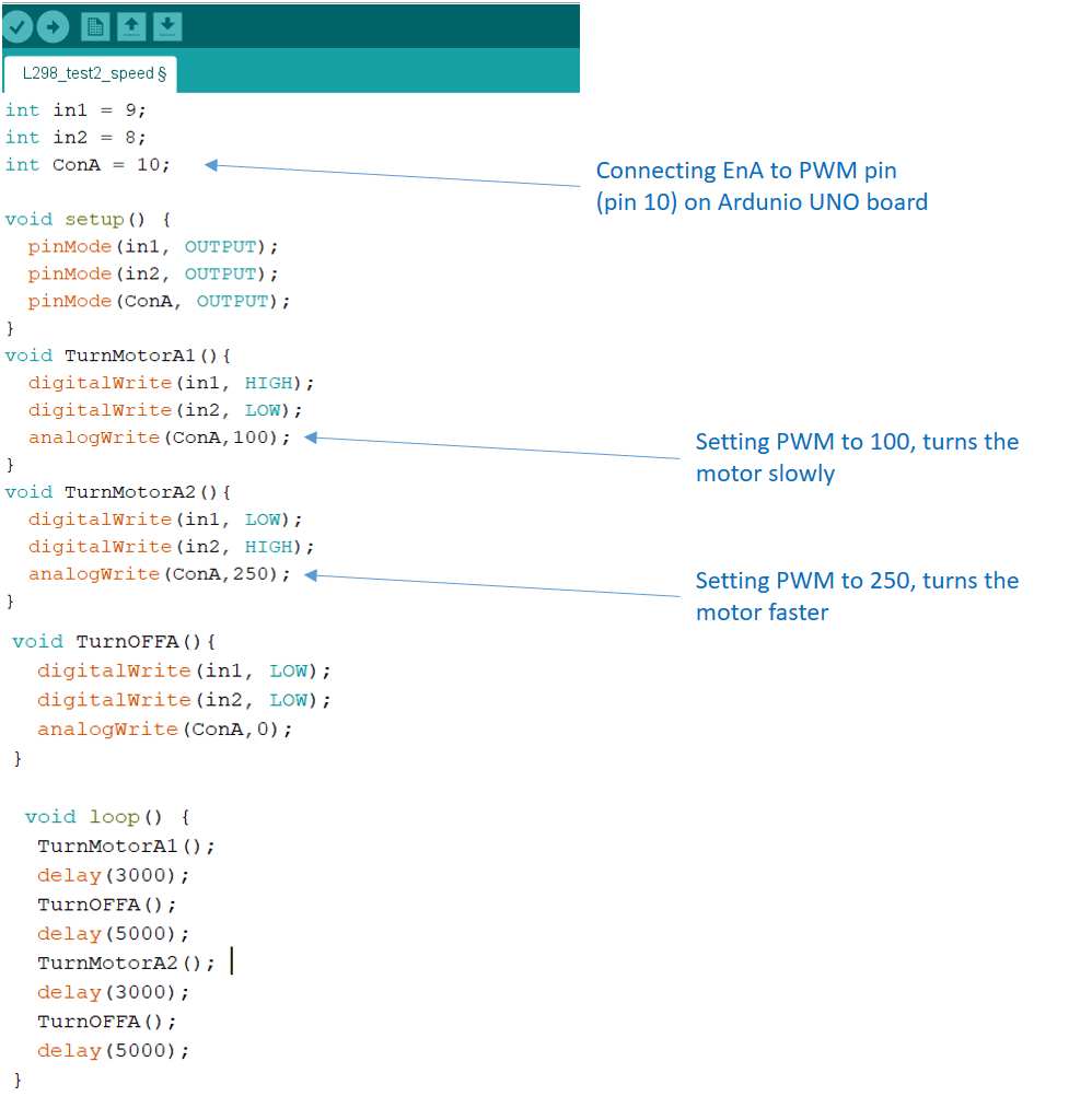
The Sketch program makes the motor spins slowly for 3 seconds stop then spins rapidly in opposite direction for another 3 seconds.
The Ardunio codes for the two runs are as follows:
to download the Arduino Sketch file for the first run.to download the Arduino Sketch file for the second run.
For my final project, I need a submersible water pump to be on intermittently to bring fresh solution to the anodic chamber of the microbal fuelcell. I plan to use the QR30B water pump. This is a 5V 2.3W brushless DC pump that is submersible.
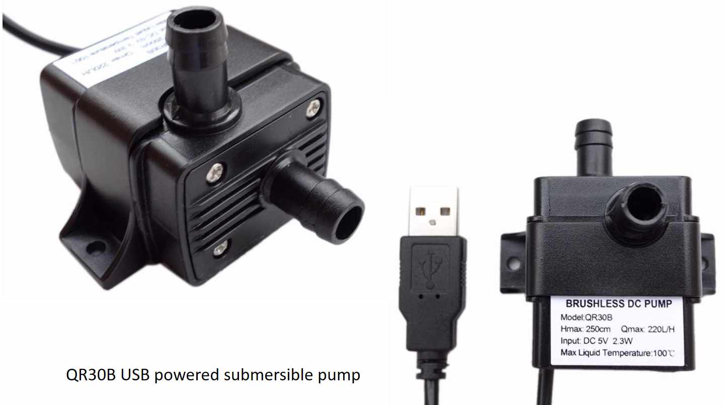
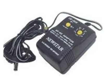
According to lastminuteengineers.com the typical voltage drop between the supply and the output is 2V. Hence to power this pump, a supply voltage of around 7V is required. I planned to use a 9-V battery to power this pump. This means a 5V regulator is required for the electronics if I want to use the same power source. I tested the pump using a Newstart AC/DC Multiple adapter set to 9V. The water pump works as planned. For the actual application I will need to determine if the flowrate is too high as it would flush out the micro-organism residing in the sponge media. The PWM command line will be added into the sketch program when required to reduce the flowrate.
The pump on for 5 seconds stops for 2 seconds then on again according to the Sketch program.
For this assignment, the QAPASS 1602 LCD is used. This is an industrial character type LCD that can display 32 characters (16 column 2 line). It comes coupled with the I2C Serial Interface Adapter Module which make wiring a breeze as there are only 4 pins on the I2C module, namely: GNC, VCC, Serial Clock (or SCL) and Serial Data.
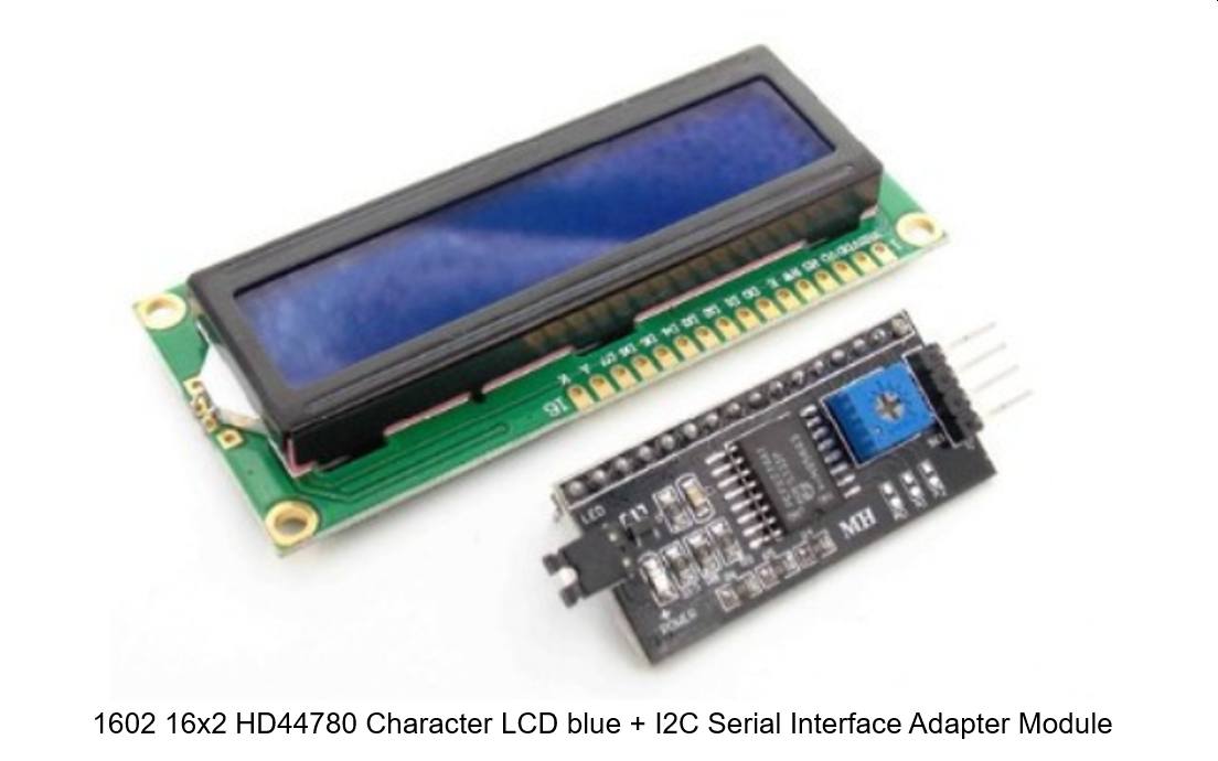
To use this LCD in Ardunio IDE, the SDA and SCL pins are connected to Analog pins A4 and A5 respectively while VCC and GND are connected to 5V and GND as usual.
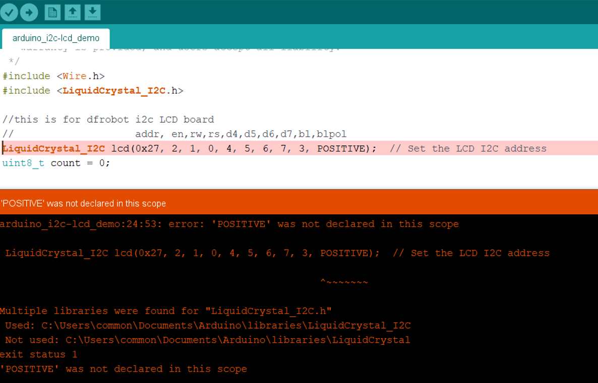
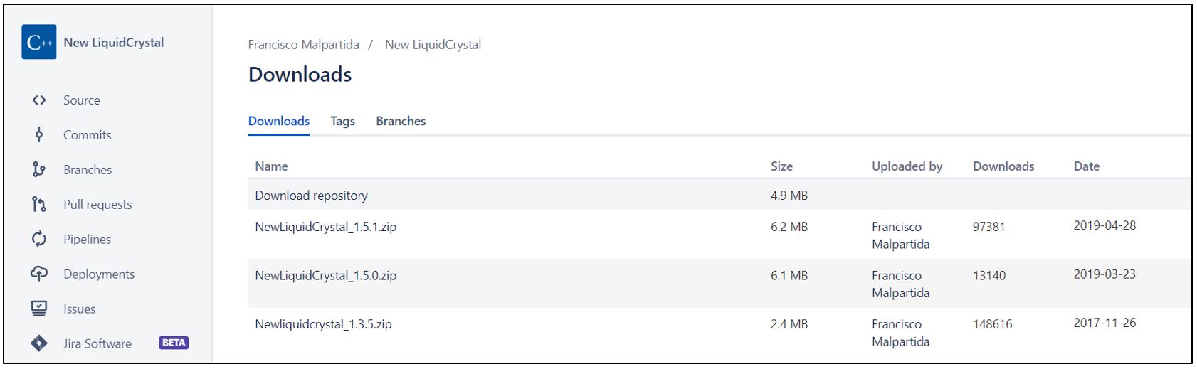
To run the Sketch program, 2 libraries are required. The wire.h library is already in the latest version of Ardunio IDE but must still be specify in the Sketch program (#include wire.h). The second library is the LiquidCrystal_I2C.h. There are several versions of this library available and may not be compatible for the hardware used.
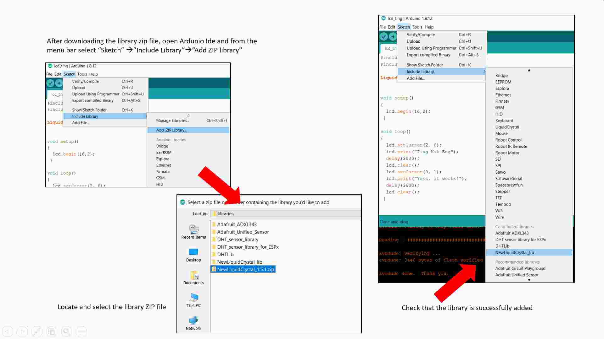
After adding the library, the Sketch file can be added and compiled. The program however failed to compile and the following error is obtained:
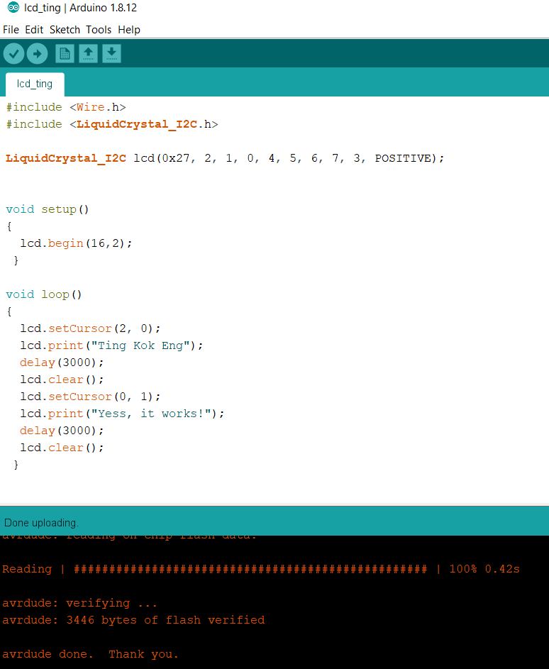
Using this new library, my Sketch program can be compiled and run
This complete the testing on the 4 output devices. The next task is to connect an output device to a new board that I have made. My work on the circuit board design and productuib is documented under the final project tab and only the vidoe showing the servo motor that is connected to my board working properly. For this test, I modified the program used above and change the output pin accordingly.
The motor will turn 90 degree, pauses for 1 second, then turn another 180 degree, wait for 1 second then return to start position