Exercise 9 - Input Devices26/3/2020 to 1/4/2020
There are 2 tasks for this week:
- Individual Assignment: Part 1: Measure something: Add a sensor to a microcontroller board that you have designed and read it
- Group Assignment:: We are to probe an input device(s)’s analog and digital signals.
The group assignment is done with Noel Kristian and Yeo Gau Siong. Our collective work is documented on the SP Fablab Website and as follows:
For the group assignment we tested the following:
- Ultrasonic sensor HC-SR04 that produces digital signal
- Temperature/humidity sensor DHT11 that produces digital signal
- Light Dependant Resistor (LDR) that produces analog signal.
Our collective work is documented on the SP Fablab Website
To simplify the workflow without making new board, ARDUINO UNO board is used for each of the sensor and the programming is done in Arduino IDE.
1. Ultrasonic sensor HC-SR04
The details of the workflow in using ARDUINO UNO with Ultrasonic sensor HC-SRO4 can be seen in Noel Kristian'sindividual page.
2. Humidity/Tmeperature sensor DHT11 sensor
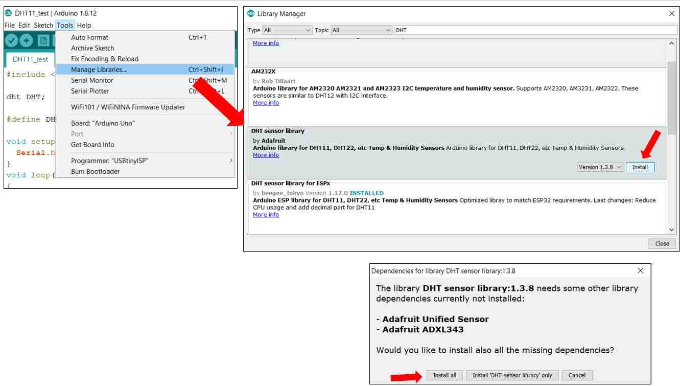
To use DHT11 in Ardinuo IDE, the library must be updated from "Tools" -->"Manage libraries"
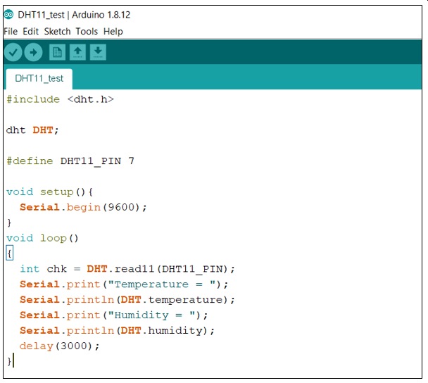
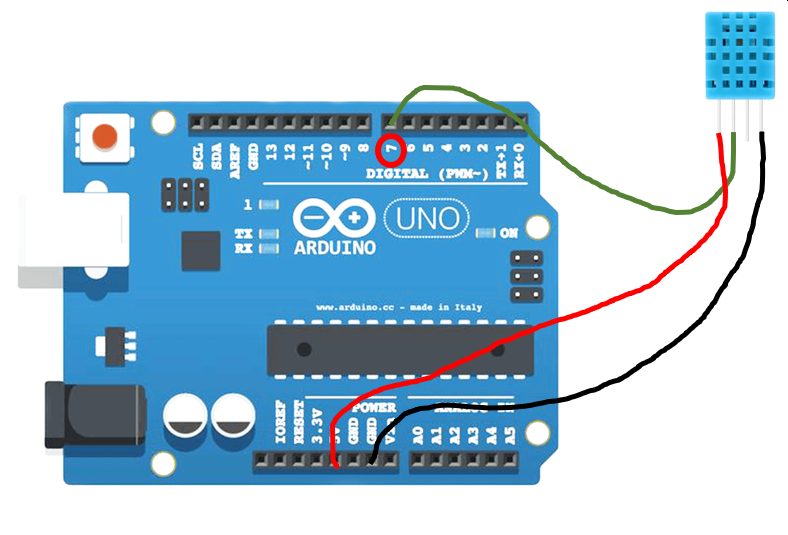
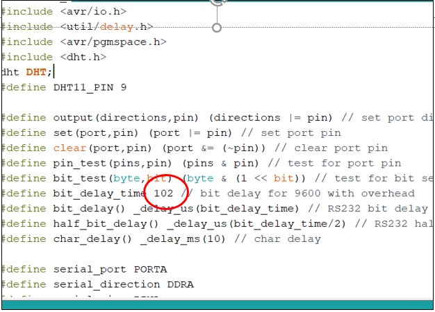
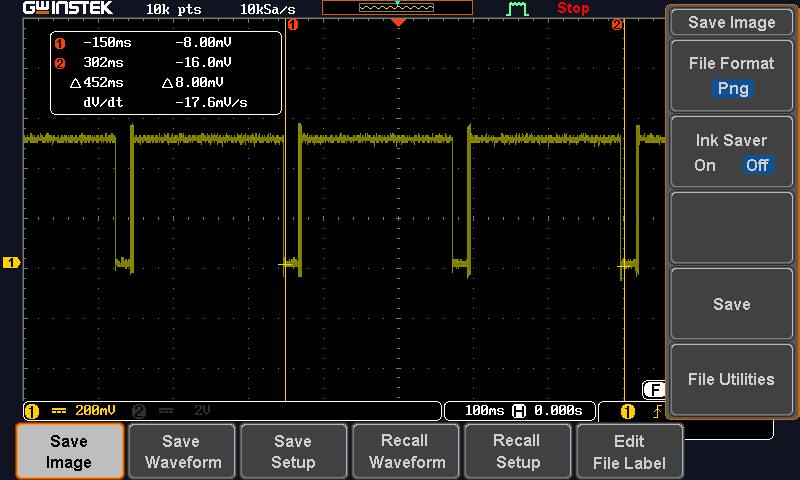
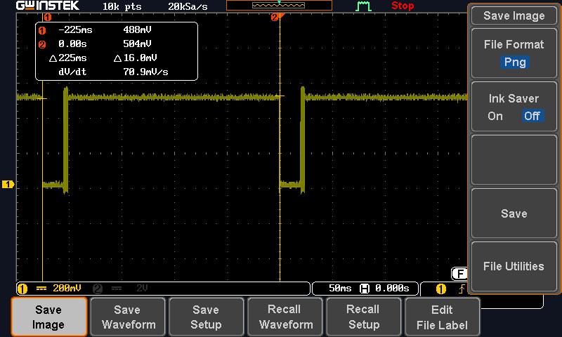
After adding the library, a simple program is written and compiled using Sketch. For connection, since the output from the sensor is digital, pins 2 to 13 can be used. Pin 7 is selected as it is at the end and easily located. Also as the sampling rate should be slower than 1 Hz, hence a delay of 3 seconds was used. However, when probing using an oscilloscope, the was changed to 200ms.
Using the "Serial Monitor" under "Tools", the humidity and temperature readings is being captured every 3 seconds. This showed that the sensor is working properly and the connection and the program correct. For the oscilloscope sampling, the delay timing is changed to 200ms for easy capturing.
Click Here to download ardunio code
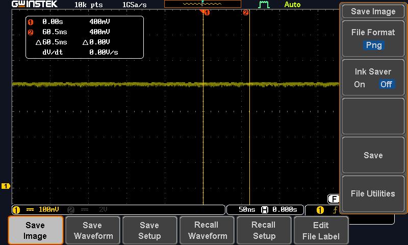
Below are the screen captures of the oscilloscope during the measurement.
3. Testing the LDR Circuit (Analog signal)
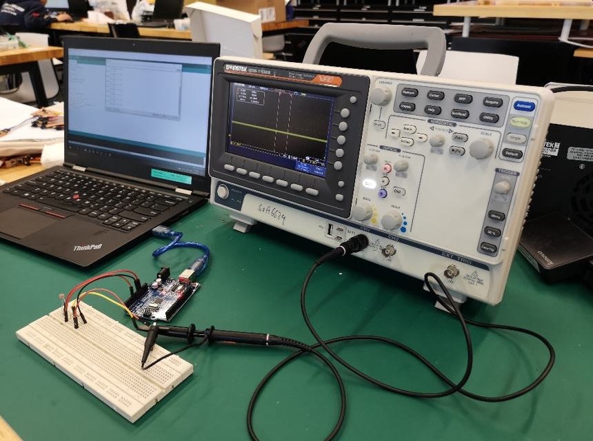
To probe an analog signal, a LDR and a 4.7 kohm resistor is connected in series. The LDR is connected to VCC (5V) while the 4.7 kohm resistor is connected to ground. The signal at the junction is tapped and analysed using the ardunio IDE and with an oscilloscope. Since the signal is analog, A0 pin on the Ardunio UNO board is used.
Below is the setup and video of the measurement using oscilloscope. It can be seen how the signals gradually changed when the LDR is not covered (exposed to light) and covered.
Below are the screen captures of the oscilloscope during the measurement. LDR not covered. Shows high signals around 400 mv
The x10 switch on the oscilloscope probe is accidentally switched on, which explains why the values are 10 times smaller than what is registered on the serial monitor.
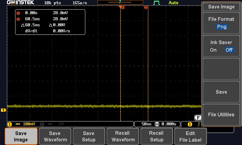
LDR Covered
LDR Exposed to light
Click Here to download ardunio code
Individual Assignment
This individual assignment is essentially about selecting a sensor and incorporated it to the microcontroller board design and use it to meansure that physical parameter (that the sensor is designed for).
Referring to the assessment guidelines for this assignment; fabricating an unmodified board is considered as electronics production and does not count towards any design skill. Hence I decided to design a new board that I can also use later for my final project.
As for my final project, the microcontroller may need to be connected to more than one sensor and/or control an output device, the ATtiny45 chip may hence be inadequate as the number of programmable pins is only 5 (excluding the reset pin). I decided to use the knowledge from Weeks 4, 6 and 8, to build my new board using ATtiny44 instead.
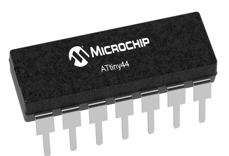 ATtiny44 microchip from Atmel
Phase One: Understanding the components I plan to use
(A) ATtiny44 microchip
Similar to ATtiny45, the full datasheet for the ATtiny84 chip is also very comprehensive (238 pages), there is also the summary of 26 pages for quick reference. They are both available from Atmel website. I felt relieved that after reviewing the datasheet for ATtiny45, looking at the datasheet for ATtiny44 is now less daunting.
Some characteristics and information about this ATtiny44 microchip that made sense to me now are listed below, they are generally similar to ATtiny45 that I have used before:
- 8-bit microcontroller with internal 8MHz clock
- 14-pin SOIC
- 12 Programmable I/O ports (the other 2 are VCC and GND)
- Each port has its own internal pull-up resistor
- Ports are multi-functional (e.g. digital I/O, PWM, TWI
- 4K Bytes of In-System Programmable Program Memory Flash
- 256 Bytes In-System Programmable EEPROM
- 256 Bytes Internal SRAM
- 8-bit Timer/Counter with Prescaler and Two PWM Channels
- 16-bit Timer/Counter with Prescaler and Two PWM Channels
- USI – Universal Serial Interface with Start Condition Detector
- 10-bit ADCs
- On-chip Analog Comparator
- Programmable configuration using Fuses
- Able to work between 2.7V and 5.5V
- Programmable Watchdog Timer with Separate On-chip Oscillator
- Speed Grade: 0 – 10 MHz @ 2.7 - 5.5V, 0 - 20 MHz @ 4.5 - 5.5V
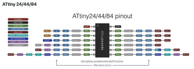
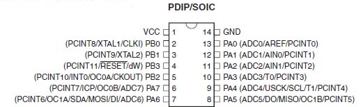 ATtiny44 Pinout from Datasheet (page 2)
(B) DHT11 - Humidity & Temperature sensor
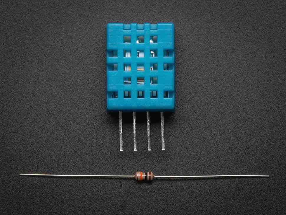
DHT-11 from www.adafruit.com
From Adafruit.com website, the DHT11 is a basic, low-cost digital temperature and humidity sensor. It uses a capacitive humidity sensor and a thermistor to measure the surrounding air, and output a digital signal on the data pin. The sensor also has a very basic chip inside that performs the analog to digital conversion.
Some technical details about the sensor are as below:
- 3 to 5V power and I/O
- 2.5mA max current while requesting data
- Good for 20-80% humidity readings with 5% accuracy
- Good for 0-50°C temperature readings ±2°C accuracy
- Sampling rate must not be more than 1 Hz (once every second).
- Body size 15.5mm x 12mm x 5.5mm
- 4 pins with 0.1" spacing
DHT11 has four pins. The left-most pin is for power (VCC), a voltage of 5V is recommended. The second pin is the data pin, a 10KΩ pullup resistor from this pin to 5.0V is required. The third pin is not used and the right-most pin is ground (GND).
Phase Two: Design the circuit
Since DHT11 is a digital sensor, using any pin will do, also since it only requires one pin (the other being VCC and GND), ATtiny45 would be more than sufficient. For my final project, I need to measure the voltage produced by a microbial fulecell MFC), this means I will need to use one of the pins for analog/digital conversion. From literature, the volatge produced by the MFC is typically between 0 and 0.5V. Since this voltage is quite small, I decided to use a wheatstone bridge and also utilise the differential ADC channels and the programmable gains.
In addition, I pullout the PWM pins, just in case I may need to use it to control a motor or water pump.
Having have a rough idea of what I want in my board, I started a new project in EAGLES and followed the instructions that I have documented for the Week 6 assignment on "Electron Design". I really appreciate the importance of "documenting-as-we-go-along" as I realised that I have actually forgotten several steps. I created the schematics without mucg difficulties. This time, I remember to use the "Name" function to define and connect the components instead of physically wiring them. The outcome is much neater and easier to read.
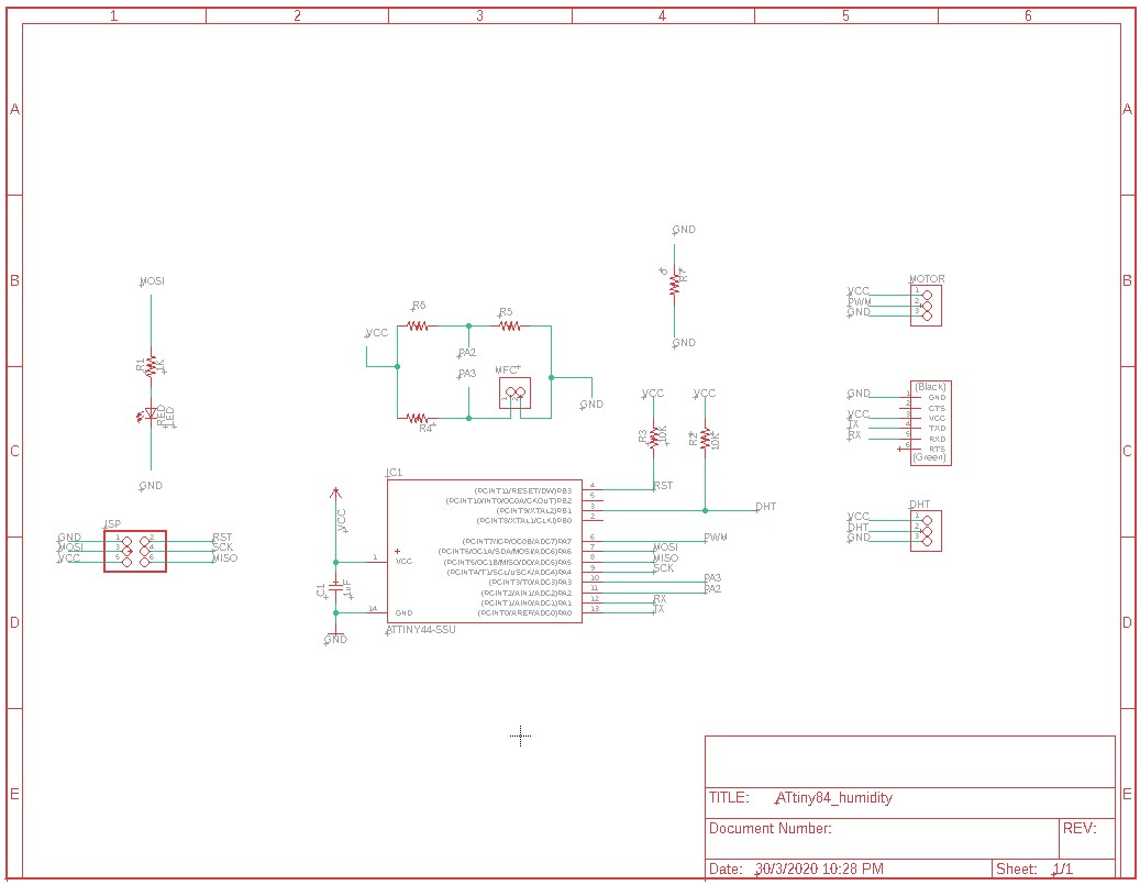
The explanation on the purpose of each part is as below:
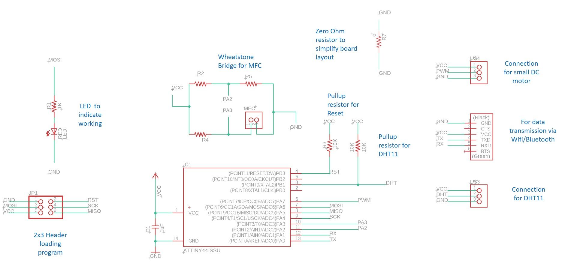
Right click Here to download the Schematic file
After completing the schematics, the next step is to do the board layout. With so many more components that in Week 6, I had a really hard time (more than 6 hours!) laying out everything properly and to pass the DRC (design rule check).
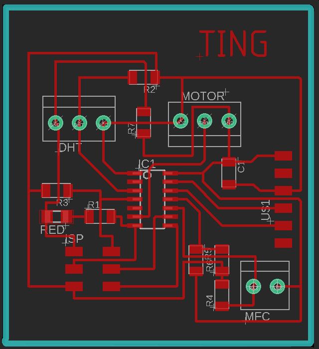
Right click Here to download the Board layout file
After completing the board layout, the next step is to generate the gcode files for the milling machine. To do this, image files in PNG format must first be exported from the board layout. Again, following my own documentation for Week6, I managed to create all the PNG image files without much difficulties. What is different is that for this board, I have to drill holes for the header pins.
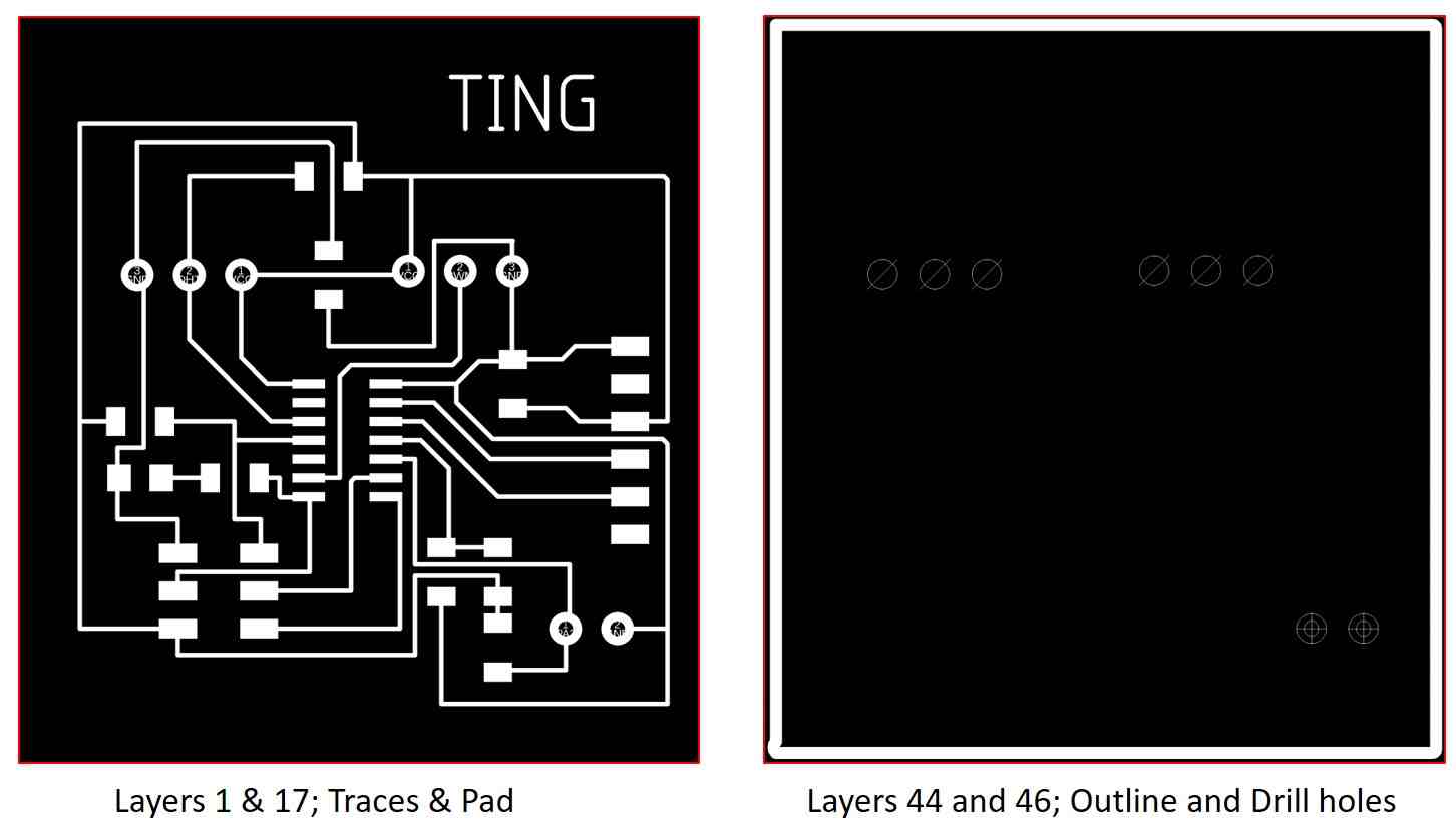
Right click Here to download the attiny84_trace.png file
Right click Here to download the attiny84_outline.png file
After generating the PNG files, the last step is to generate the gcode files. I used MODS again due to its simplicity. The steps are documented in Week 6 Assignment of "Electronic Design"
Right click Here to download the gcode file for the traces
Right click Here to download the gcode file for the outline
Phase Three: Fabricating the board - Milling with StepCraft CNC machine.
For the traces, the end mill used is V-shaped 0.1mm 10degree while for the outline and holes, 0.8mm flat end mill is used. The setup and operating procedures are captured in Week 4 and Week 6 assignments and are hence not included here.
Phase Four: Stuffing the board
As the design/requirement of my final project is yet to be confirmed, I have decided to leave part of the board such as the wheatstone bridge for the microbial fuelcell and the PWM pin for motor control unstuff and focus only on components necessary for meeting this week's assignment requirement.
For the board production, I encountered several issues, while they are good learning points, they have rendered my board unsuitable for my final project. I decided to made changes to the design and mill a new board, however due to machine availability and time constraints, I decided to make do with this board first for the weekly assignment first.
Issue 1 - Unavailability of terminal socket
During the milling process, the StepCraft program stalled and the holes are not milled. I am not confident encough to align the cutting tool to the exact smae place before the program stalled so I decided to manually drill the holes instead. The smalled drill bit that I can get hold of is 1.5mm, as a result the holes I drilled are too big for any pin and make soldering extremely difficult.
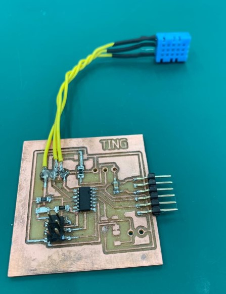
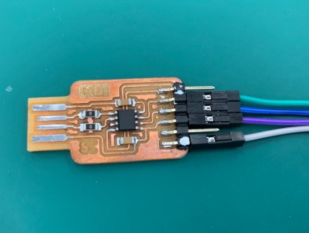
After drilling the holes, I approached the technician for the components. I should have checked with the Fablab technician at the design stage! The Fablab does not have the terminal socket that I can used. After consulting my coach, Rodney, I decided to solder the wires directly onto the board for this week's assignment.
Issue 2 - Difference between Design and Actual Fabrication
In EAGLES, everything looks OK, DRC will 12 mils gap also indicated no issue, however when I run mods, the toolpath actaully showed that a trace and 2 pads actaully fused together but I have take for granted that everything should be Ok and did not check carefully.
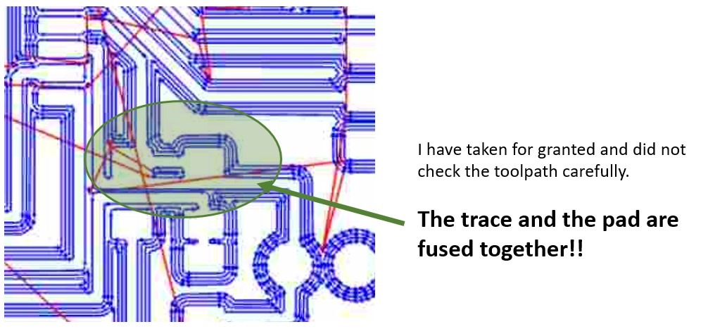
As a result, I have to use a penknife to carefully separate the trace from the pads. Despite all this, I have managed to get the board to work for this week's assignment
The partially stuff board is as follows:
Phase Five: Programming with Arduino IDE using Sketch
Although I have added the Ardunio Core to support the ATtiny45 chip earlier, after installing the support core for ESP8266 for Week 7 assignment, somehow the ATtiny boards cannot be found under "Tools"-->Boards. I have to go to "File"-->"Preference" and insert the URL (http://drazzy.com/package_drazzy.com_index.json) from Spence Konde again before the ATtiny board options can be dsiplayed under "Board Manager"
After selecting the correct board option, the Ardunio IDE is ready to test the program I wrote. For my program, since my DHT11 is connect to PB1, I referred to the ATtiny44 pinout to find the equivalent Ardunio pin defition which is Pin 9. My TX and RX were connected to A0 and A1, likewise, I defined them as Pin 0 and Pin 1.
To my dismay, the simply sketch program took up 104% of the available 4K memory that ATtiny44 has! I should have used ATtiny84 or ATtiny1614 instead. Sighhh! I approach my coach Steven for advice. Steven used Neil's code and modified it to suit my application. The program uses only 72%!
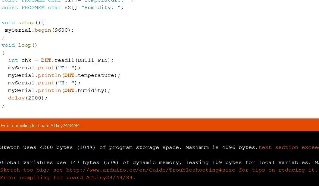
My Program is too BIG
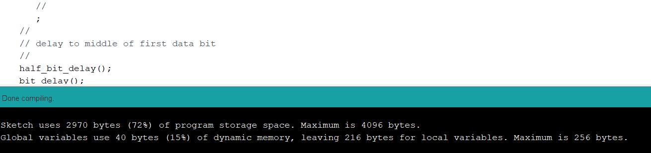
Steven's Program
Right click Here to download my sketch file
Right click Here to download my coach's sketch file
With the program settled, the next step is to upload the program onto my partially-stuff board with the USBTinyISP that we made in Week 4. The progress was smooth and the program is successfully loaded.
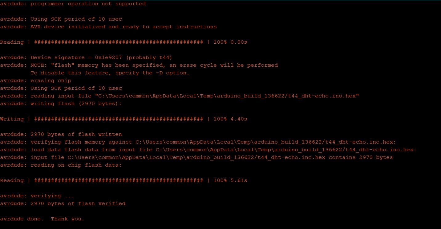
Program Uploaded
To run the program, I borrowed the FDTI board from my coach.
Steven's FTDI board
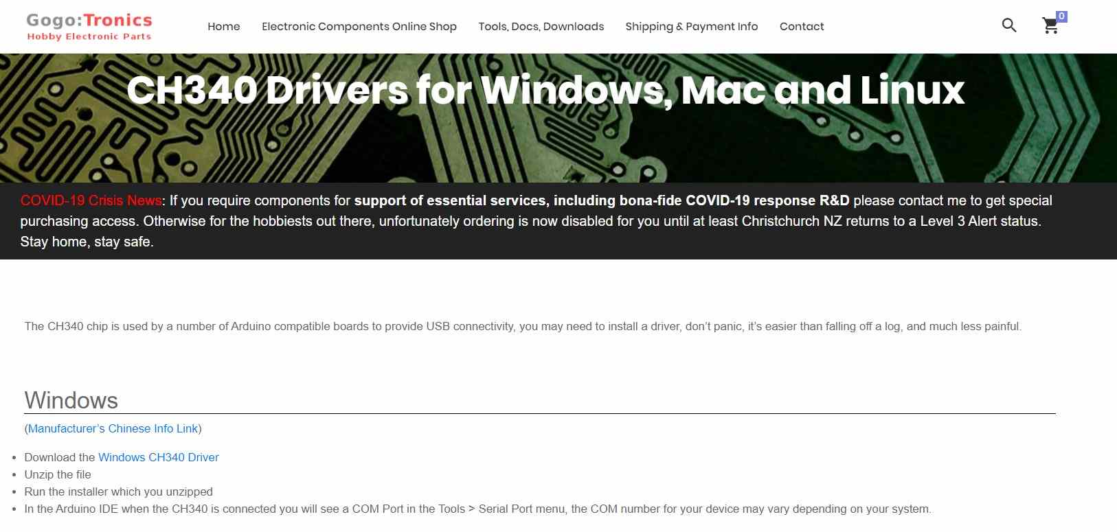
To get this board to work on my computer, the windows driver must first be installed. I went to Go-go-tronics to download and install this driver.
After installing the driver, I am still unable to get the humidity and temperature information displayed on the serial monitor. My coach explained that the sampling timing of the FTDI is probably wrong. He suggested that I tap the output from the board using an oscilloscope. This is the video of the signal I get. Although it is a mad rush with many mistakes, I can say that the assignment for this week is completed.