Exercise 7 - Computer-Controlled Machining 11/3/2020 to 18/3/2020
There are 2 tasks for this week:
- Group Assignment: Test runout, alignment, speeds, feeds, and toolpaths for the Versatil 2500 large-format CNC milling machinee
- Individual Assignment: make (design+mill+assemble) something big
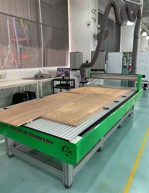
Versatil 2500
The group assignment is done with Noel Kristian and Yeo Gau Siong.
Our collective work is documented on the SP Fablab Website and hence only my learning and reflections are documented here
Individual Assignment
Before doing the individual assignment, the group spent sometime to familiarize ourselves with the terminologies and safe operation of the machine. These learning are recorded in the group assignment page. Only the safety pointers are included here again because of its importance.
(A) Safety
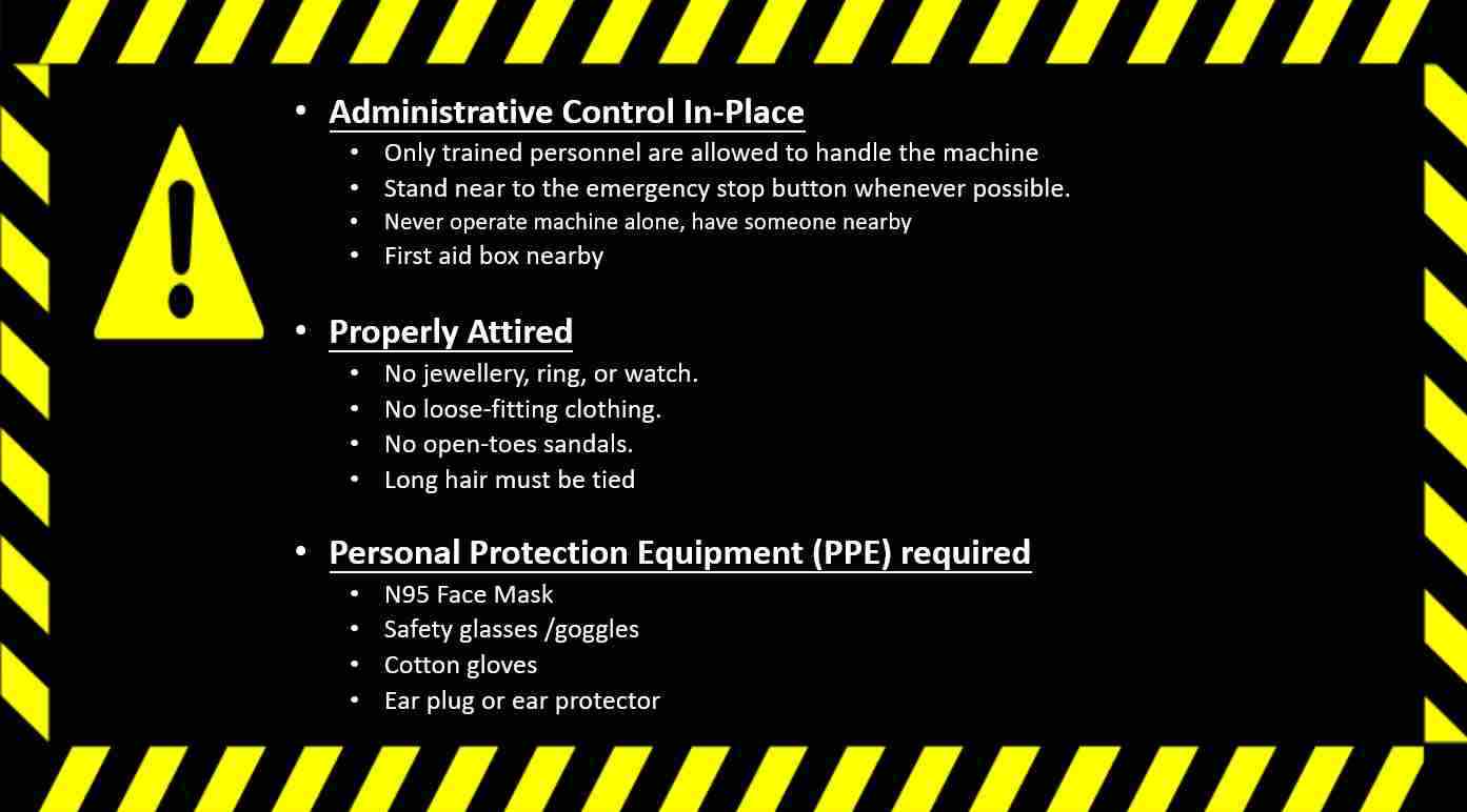
Safety Precautions for handling the CNC machine
(B) Mini Prototype
For the individual assignment I plan to design something completely new instead of modifying a design from one of the many training videos. To ensure that the design works, I decided to make a small prototype using laser cutting skills that I have learnt from the "Computer-Controlled Cutting" lesson. This is an image of the prototype.
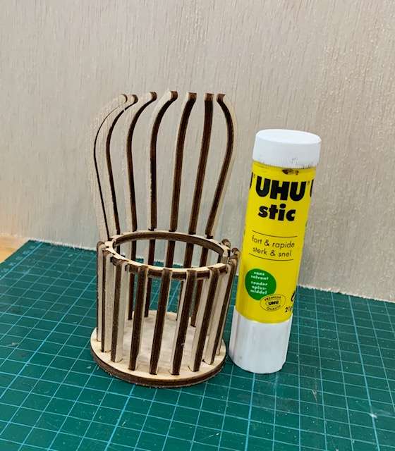
Mini Prototype for better visualisation
(C) Operating Versatil 2500
Versatil 2500 is a CNC (Computer Numerical Control) Milling machine, meaning the cutting tool will follow a tool path that is preloaded into the machine. Hence before the machine can cut, the tool path file (*.tap) must first be generated and loaded. There are several ways to do this. One way is to import a vector drawing in dxf format into a CAM software such as VCarve Pro to generate the tool path file. Another way is to use the CAM software within Fusion 360 to produce the tool path file. I have tried both methods but feel that VCarve Pro is much more intuititive and easier to use.
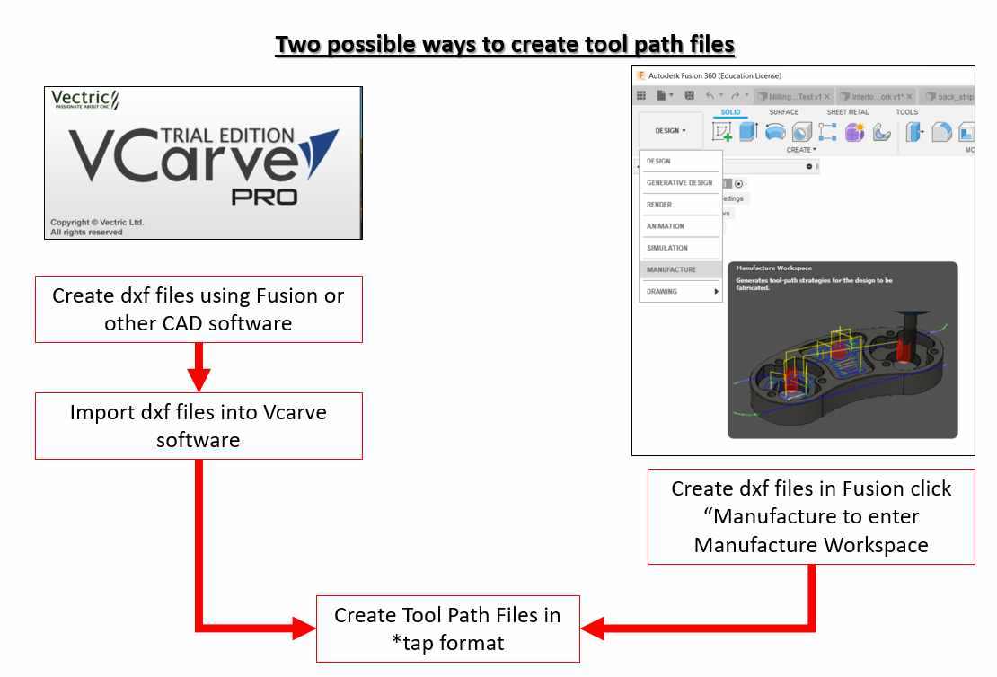
Step1: Prepare the tool path file (*.tap) with VCarve Pro
(C-1) Preparing the dxf drawing
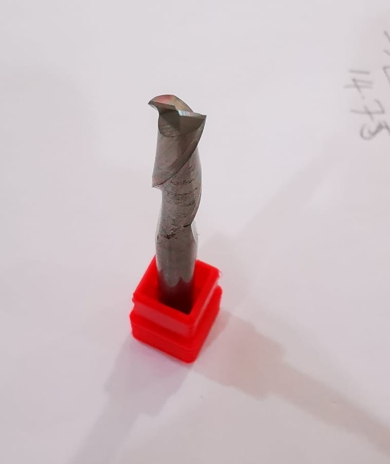
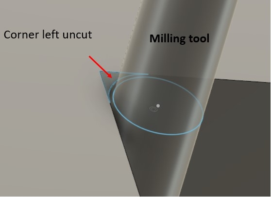
Referring to the image of the 2-flute cutting below, the diameter is 6 mm. When cutting internal corners, there will be portions that will be left uncut. These uncut portion will prevent straight edge pieces from slotting into each other completely.
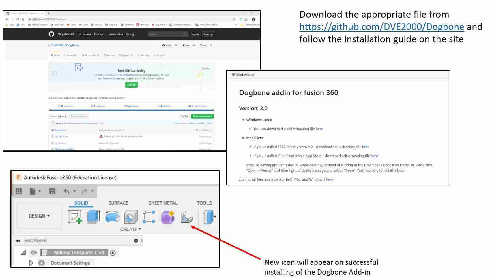
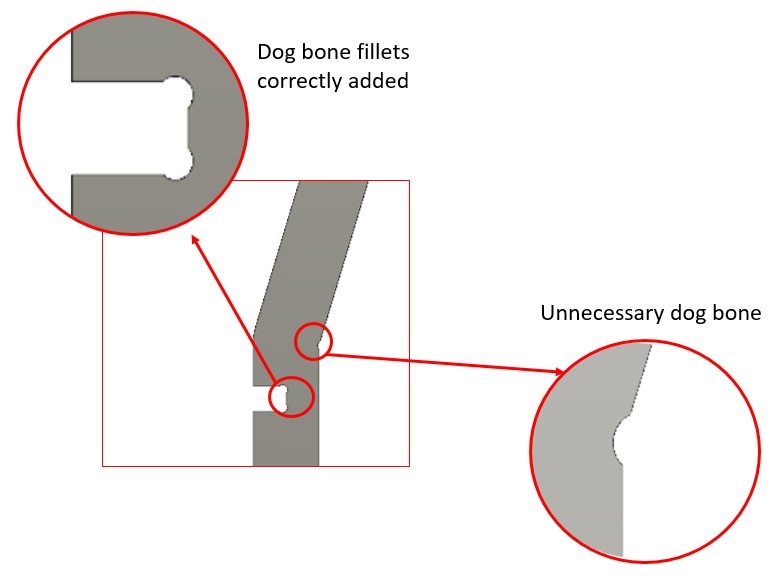
With this add-in, dogbone fillets can be added to all the corners with a few mouse clicks. While this is extremely convenient, the hindsight is that the fillets are added to corners where they are not required.
The next thing is to layout the pieces to be cut on a flat surface (known as Nesting) so as to minimise wastage of the stock. To do this, there are again Add-ins, I have however decided to use VCarve Pro to do the layout directly.
(C-2) Using VCarve Pro 10.0
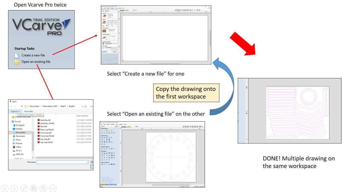
The dxf file is first loaded onto VCarve Pro by opening an existing file. VCarve Pro does not allow multiple dxf files to be opened on the same workspace. The trick to go around this is to open the program twice. For the first one, a new file is created, while on the second VCarve program, the "Open an existing file" command is selected. The drawing from this workspace can then be copied and pasted onto the new file that was created.
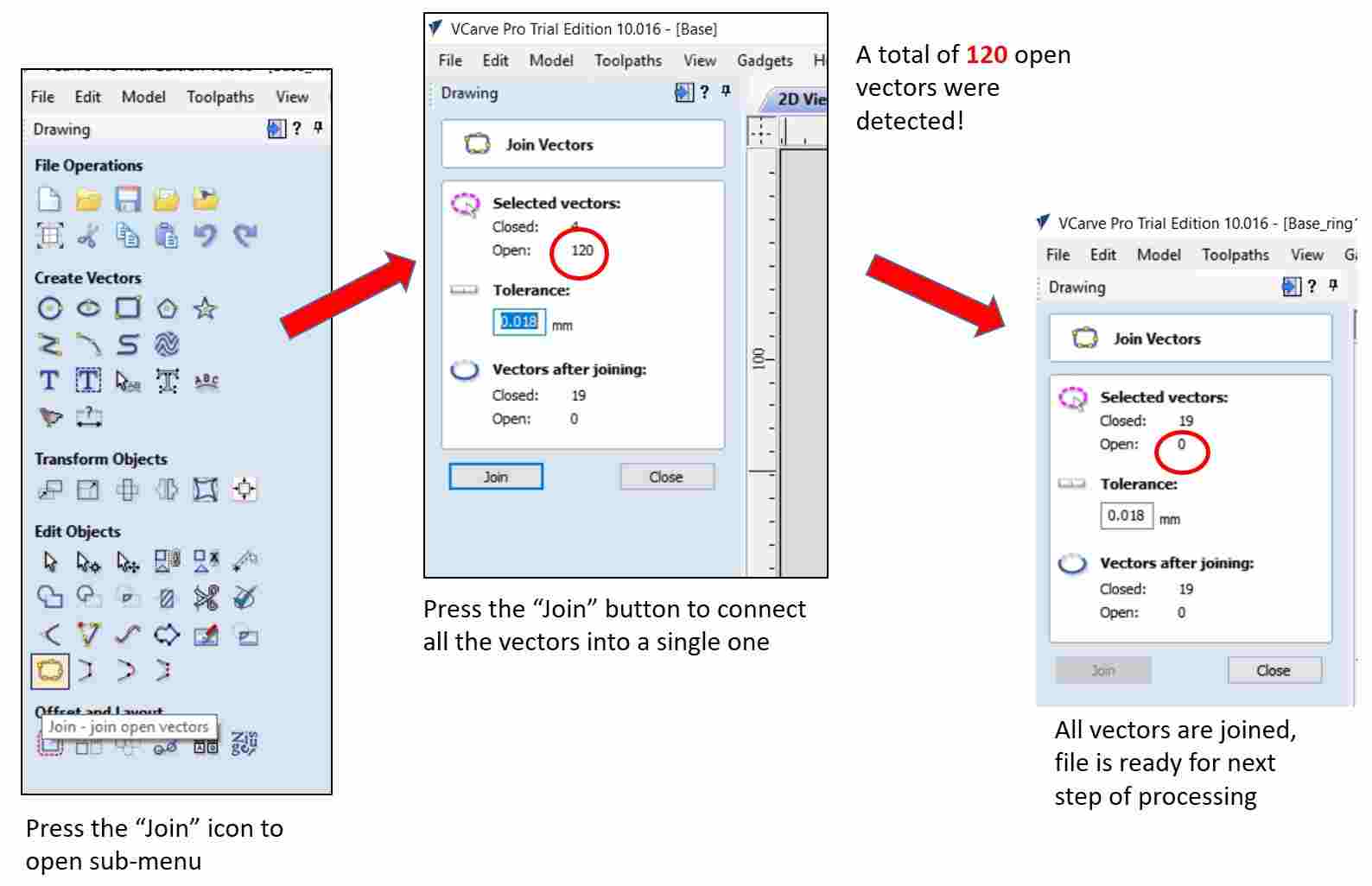
When the drawing is successfully joined with no open vector, the next step of processing can commence. By clicking on the icon on the left of the "2D-View" button, a toolpath command will open up and the required operation and settings have to be input.
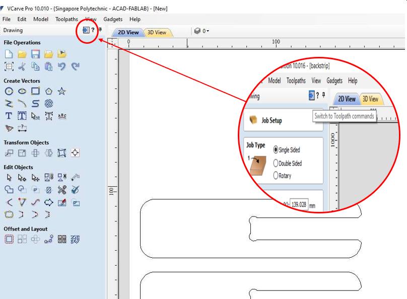
A toolpath menu will first open up and the required operation and settings have to be input.
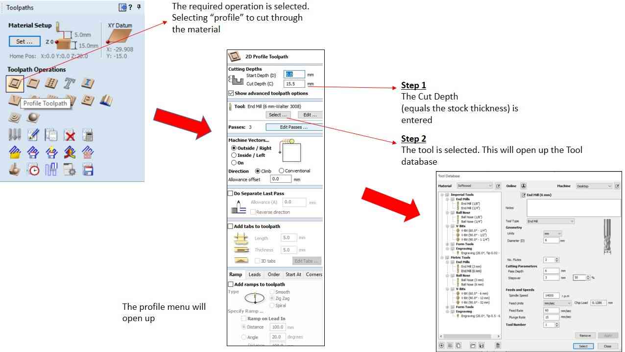
- Select the required operation. "Profile" for cutting through, "Pocket" for cutting only a certain depth.
- Selecting the "Profile" option will open the "profile menu" where the followings must be set
- Cut depth
- Tool & Tool setting
- Tabs
The cut depth is typically the same as the stock thickness
The Tool & Tool Setting sub-Menu will open up on clicking on the "Select..." button
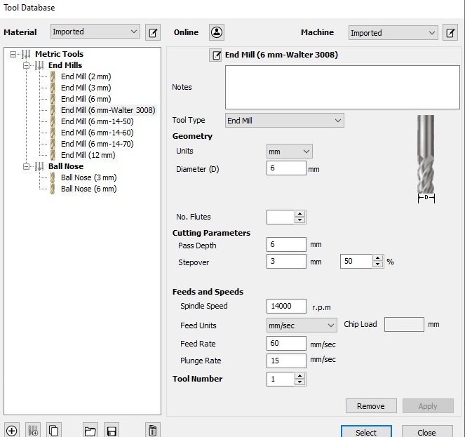
On this sub-menu page, the correct cutting tool must be selected. Following that the "StepOver"; the spindle speed; and the Feedrate must be specify. Next is the number of passes mus be set. The cutting depth for each pass is generally limit to the diameter of the cutting toolThe next important thing is to add "tabs". As mentioned in our group assignment,tabs are required to hold the work piece down and prevent movement during the milling processes. While the work piece is more secured with more tabs, having too many tabs will waste a lot of time as these tabs have to be manually chiselled off after the milling process. One important learning point is the placement of the tabs. Small gaps, tight corners and curves should be avoided as removing them will be very challenging.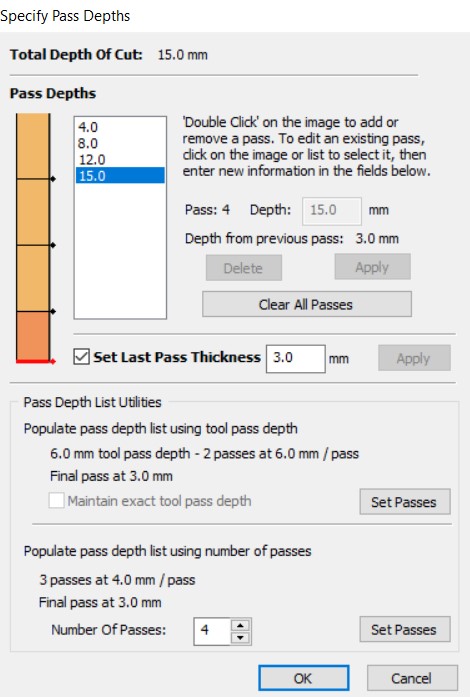 After all the above is done, the final step is to click on "calculate" at the bottom of the menu to generate the gcode file.
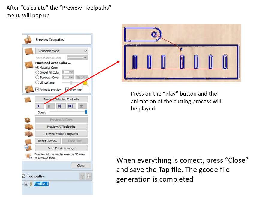
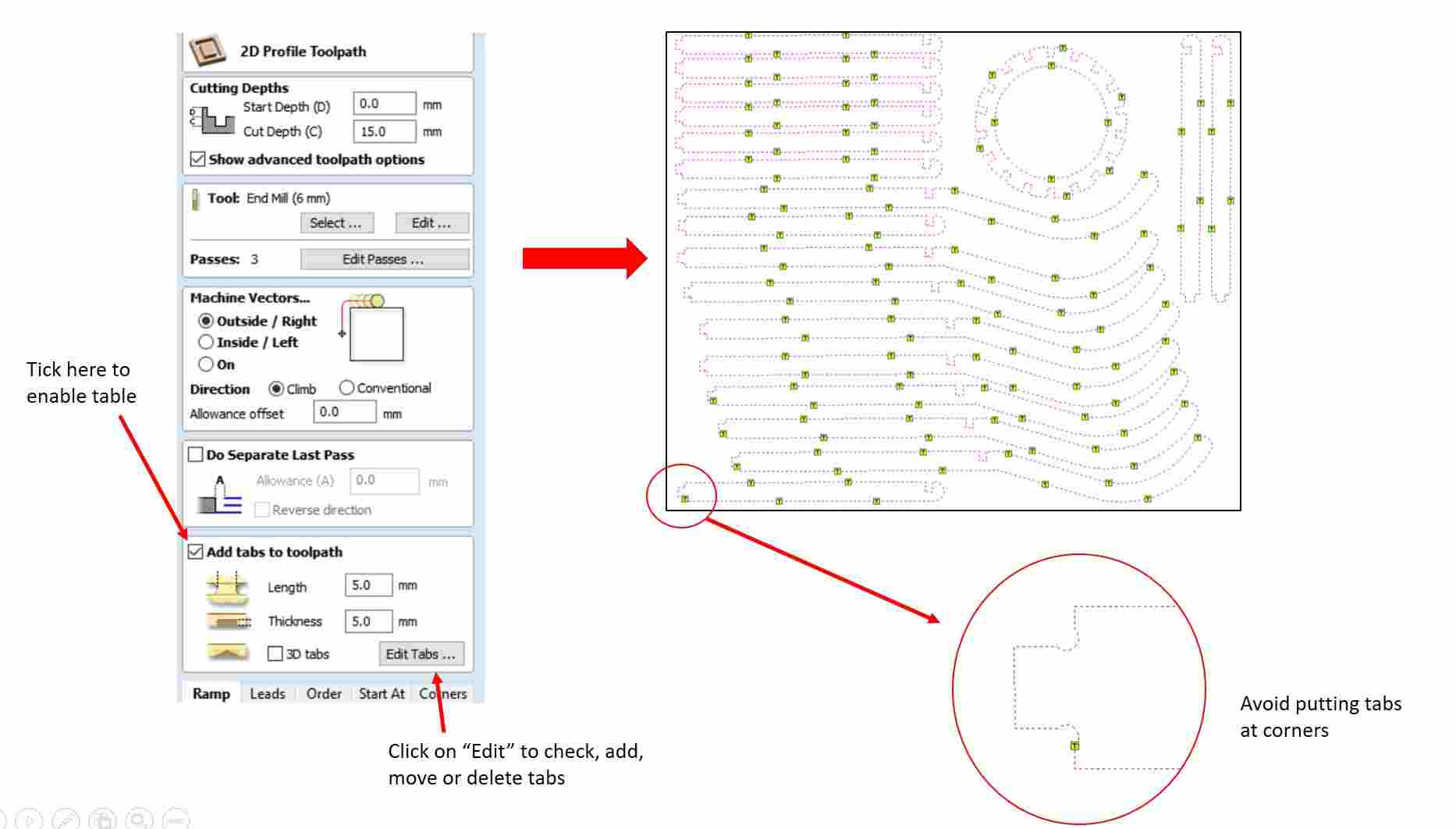 After "Calculate" the preview menu will pop up and the animation of the cutting process can be viewed to check that everything is correct before saving the gcode file in Tap format.
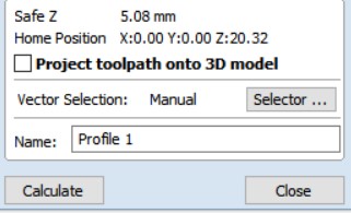
(C-3) Cutting the Design
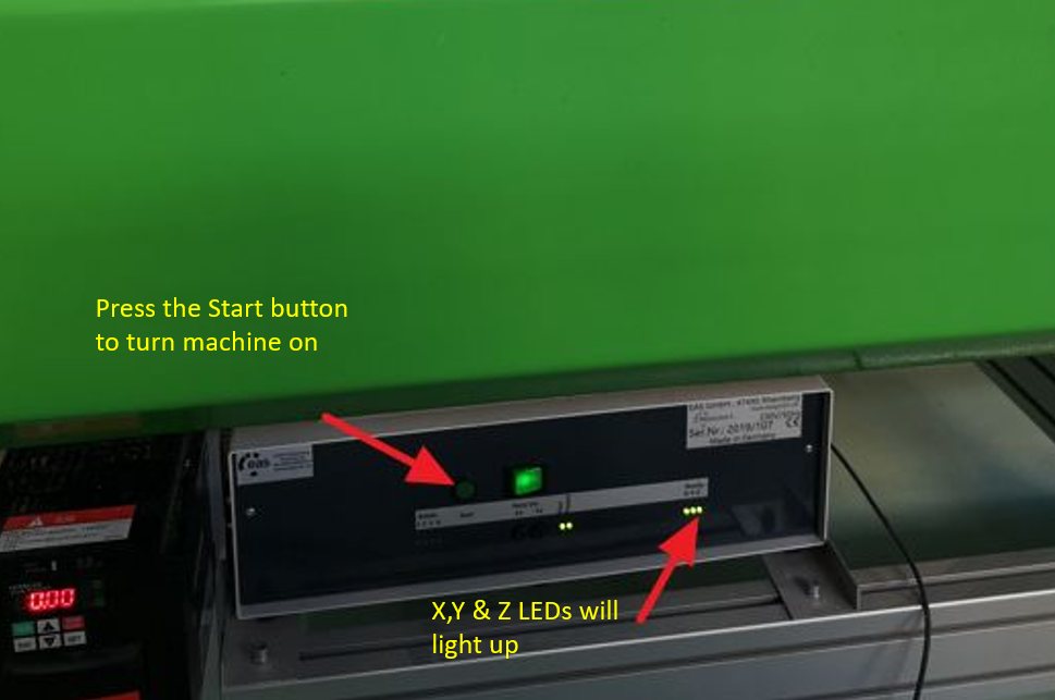
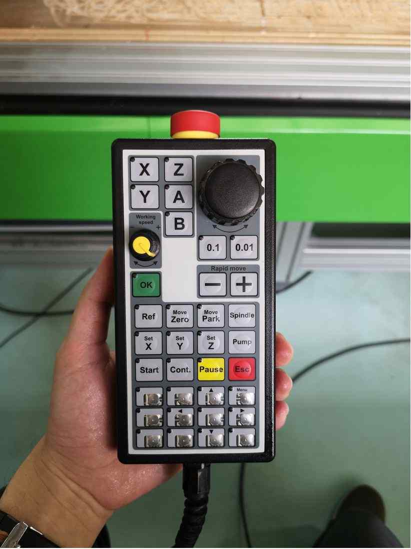
The first step is to load the tap file. Loading the file to the CNC Router software, NC-EAS(Y) Pro is similar to opening a Microsoft Word file. Following that, the milling machine can be powered on by pressing the ON button. The green led will be lit and subsequently the X, Y and Z LEDs will light up.
Next is to perform the spindle positioning
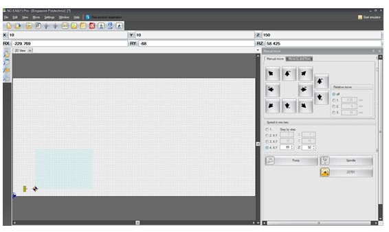
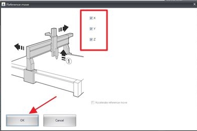
To position the spindle at the required location, the "reference move" on the menu bar is selected. After checking the X, Y, and Z boxes and press OK, the spindle will move to the default X, Y and Z positions. After this step, the spindle can be moved to the desired X and Y position using the hand controller and set the X and Y origin by pressing the buttons on the handheld controller or via the computer interface,
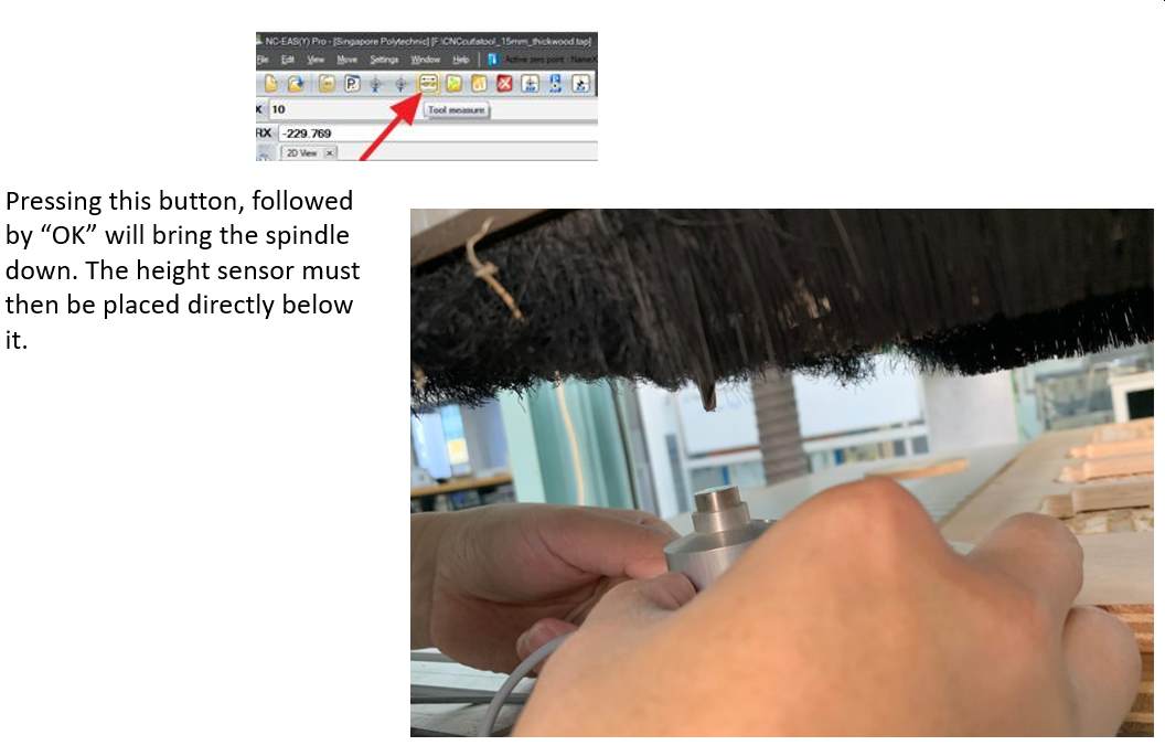
For the Z-direction, the "tool measure" button on the menu bar is selected instead. On clicking on OK the spindle will begin to descend slowly. At this instance, the height sensor must be placed directly below the cutting tool.
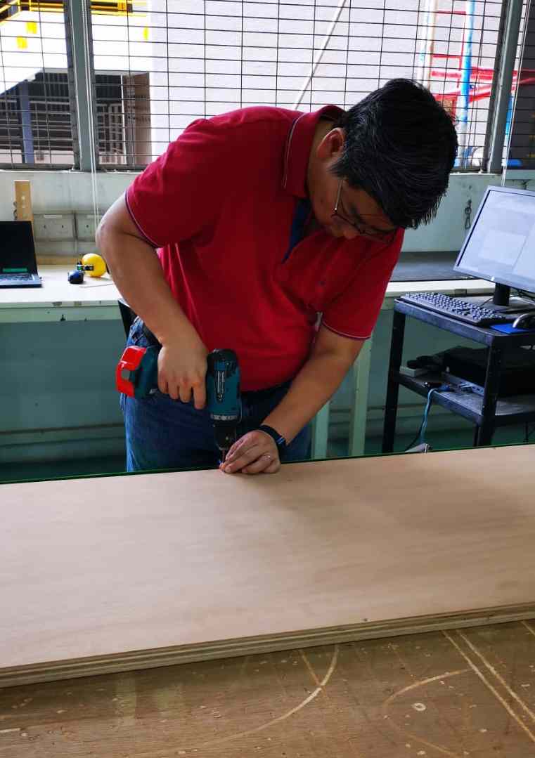
After setting the X,Y position and calibrating the Z direction, the next task is to secure the stock onto the sacrifical board to reduce the effect of board warppage.
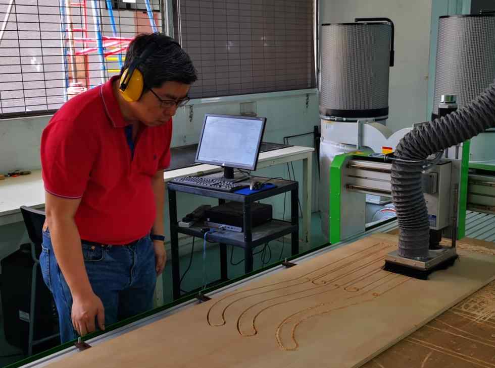
Once alignment and board securing is completed, milling can commence, when milling it is important to wear ear protection, turn on the vacuum and monitor the entire cutting process
After the milling is completed, the tabs must be manually removed with a chisel in order to separate the work pieces from the stock.
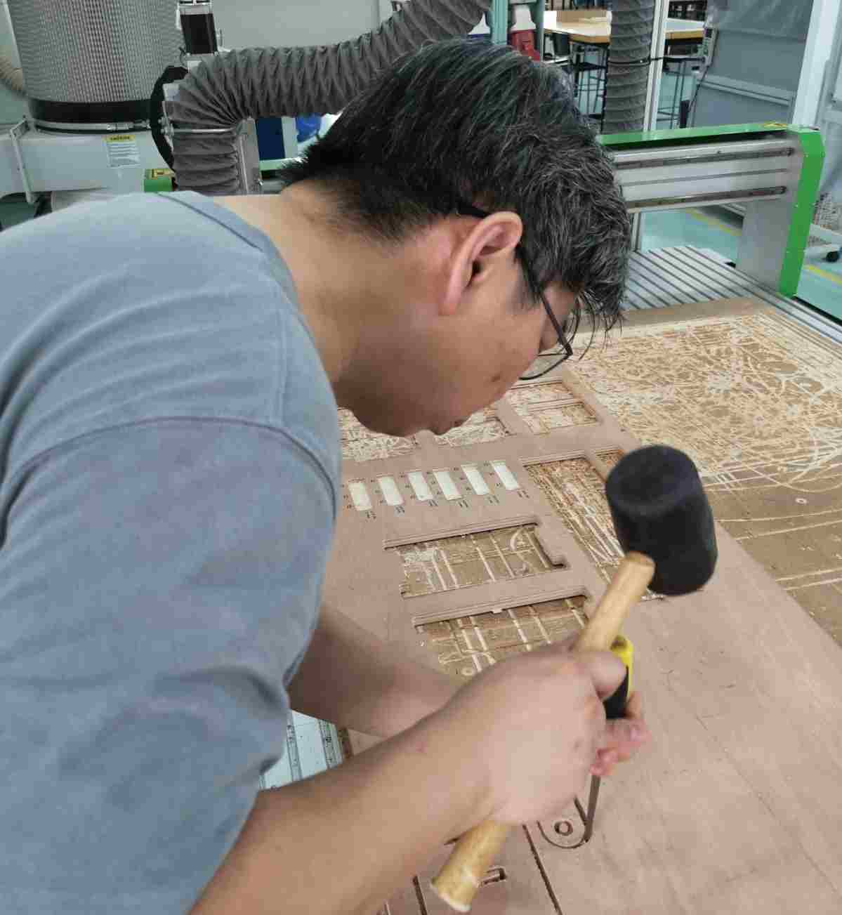
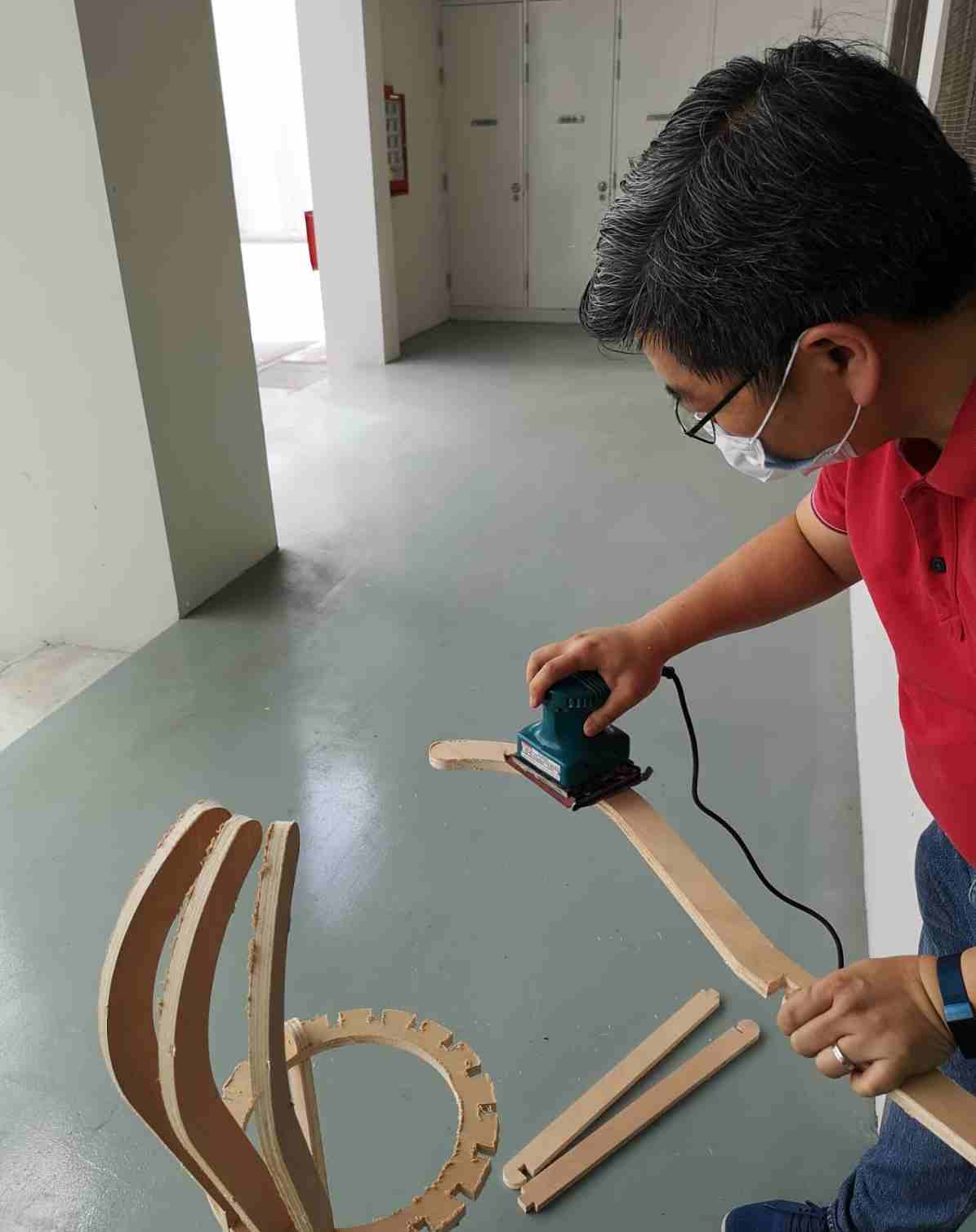
Before assembling, the rough edges of the work pieces are sanded off. Face-mask should be worn to avoid inhaling the saw-dust
Completed Something BIG
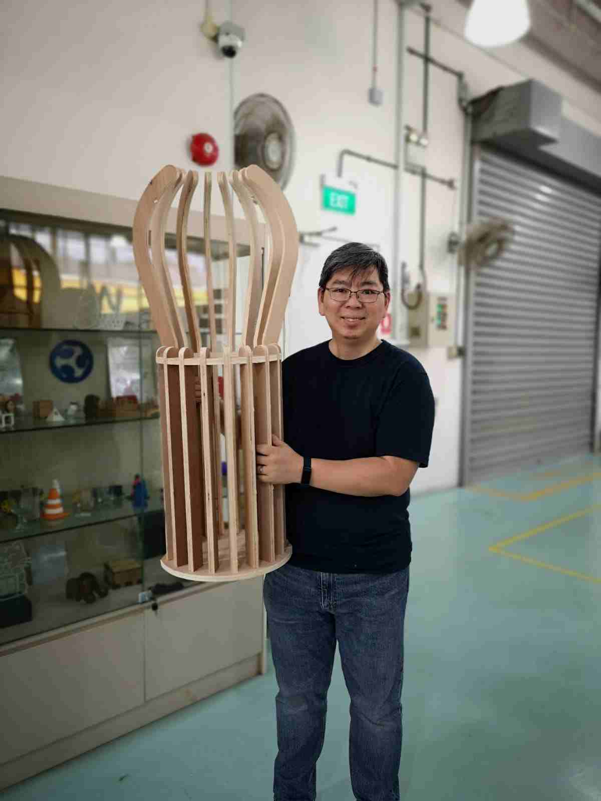
What is this? An Umbrella holder? A Chair?
No! It is a better Paper Bin!
All the Fusion 360 files are available for download individually from Autodesk360.com directly or collective as a Zip file