Exercise 5 - 3D Scanning and Printing 26/2/2020 to 3/3/2020
This week's assignment consists of 3 parts:
- Group Assignment: Test the design rule for the 3D printer in SP FabLab
- Individual Assignment 1: Design and 3D print an object that can not be easily made using subtractive technology
- Individual Assignment 2: 3D scan an object (and optionally print it)
Group Assignment: Test the design rule for the 3D printer in SP FabLab
This group assignment is done together with Noel Kristian and
Yeo Gau Siong.
Our collective work is documented on the SP Fablab Website and hence only my learning and reflections are documented here
What I have leant:
- Layer height (under quality) does not improve the finishing significantly between 0.1mm and 0.2mm although printing time can be doubled>
- Bridging actually becomes worse with small layer height
- How to use the slicer software (Cura 4.5) to generate gcode files for 3D printing
- The importance of print bed levelling (calibration)
Individual Assignment 1:
Design and 3D print an object that can not be easily made using subtractive technology
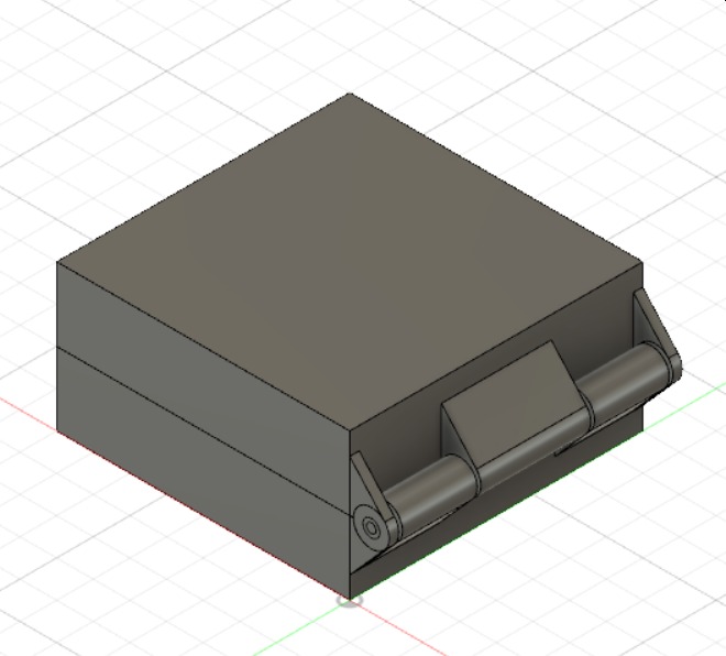
For this assignment, due to time constraints and machine availability, we are advised to design and make something small. I decided to make a hinge. I found the following 2-part video tutorial by Kevin Kennedy very useful
Video Tutorial Part 1Video Tutorial Part 2
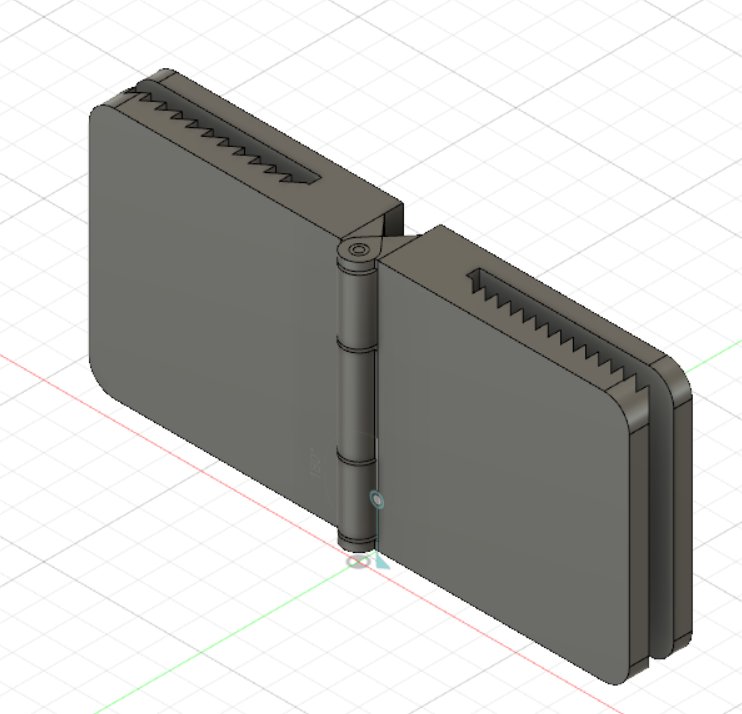
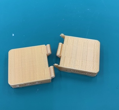
Following the instructions in the video, I successfully created my hinge. I have modified the design to exclude the "Shell" step to hollow out the box so that I can have a solid block of material
I also learnt how to rotae a component and add a motion in Fusion 360. The commands to do this are: Assembly --> As-Built Joint -->Revolute --> Select centre of rotation.
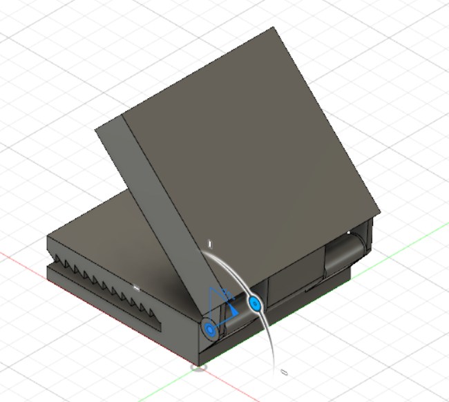
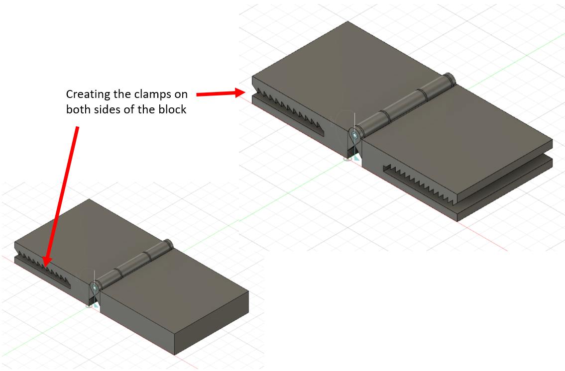
After this, I created the clamps on both blocks are follows
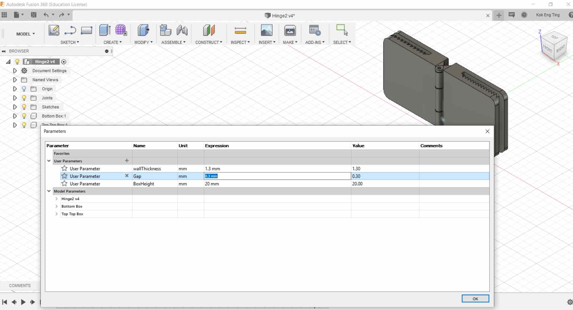
As the hinge seems to a little too loose, I decided to reprint again but reduce the gap to 0.3mm instead. As I have setup the parameters earlier, changing this was a breeze.
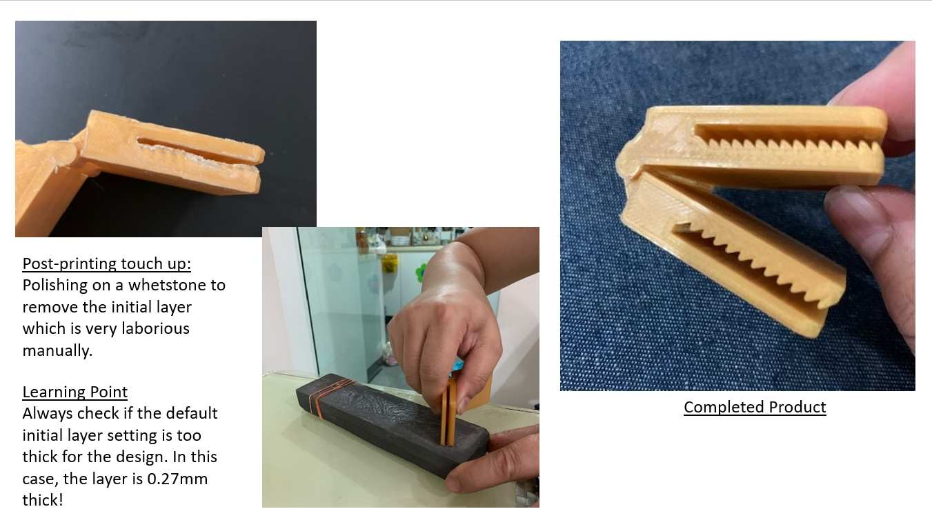
Using 0.3mm, the gap becomes too small. Although our characterisation showed that the minimum clearance is 0.2mm, the model printed with a gap of 0.3mm is too tight and broke when I tried to turn it.
Click to download STL file
Click to download Fusion 360 file
Individual Assignment 2:
3D scan an object (and optionally, print it)
For this assignment, I tried 2 different methods:
- 3D scanning using 3D scanners
- Photogrammetry with a handphone
2 different 3D scanners were evaluated. They are the NextEngin Desktop Scanner and the Sense 2 handheld scanner
The user interface for both scanners are easy to use. For the NextEngine Scanner, the object is placed on the turntable.
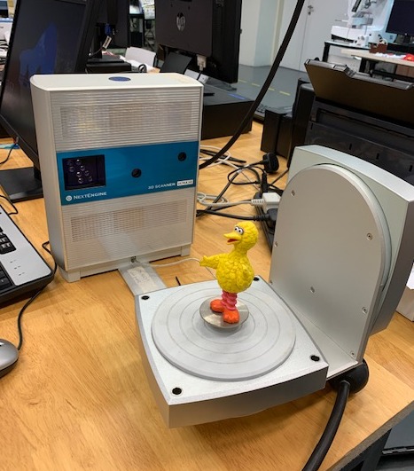
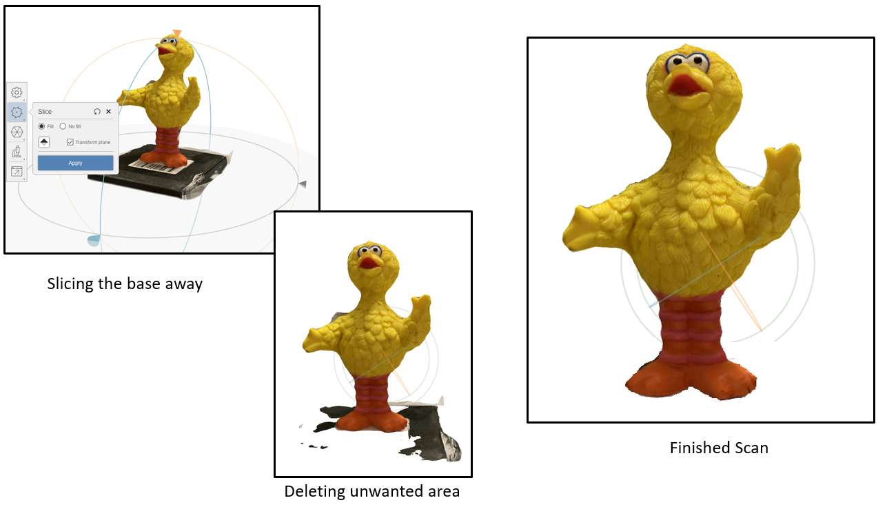
After a few mouse clicks, the scanning starts. Scanning took more than 40 minutes, the post scanning processing however was not easily and I am not able to get a good scan at this time. Scanning using the handheld scanner is more successful. For the scanning, the object can be stationary and the scanner move around it, or the scanner can be stationary and the object is revolved at its own axis. By mounting the object on a turntable, a reasonable good 3D scan is obtained as follows:
For Photogrammetry, Recap Photo software from Auotdesk is used.
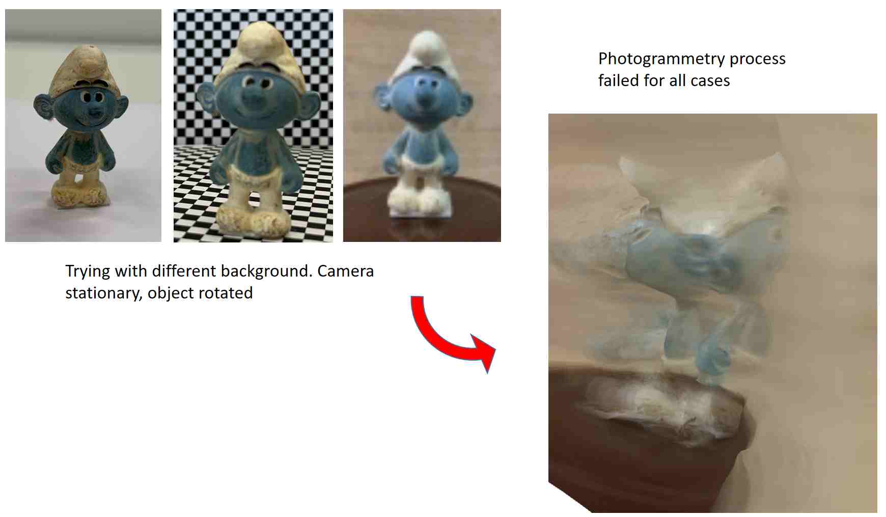
For Autodesk Recap Photo, a minimum of 20 and a maximum of 200 photographs taken from different angles of the object must be used. Unlike the 3D scanner, fixing the camera and turning the object cannot work. There must be significant changes in the background for the software to capture the object from various angles.
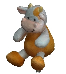
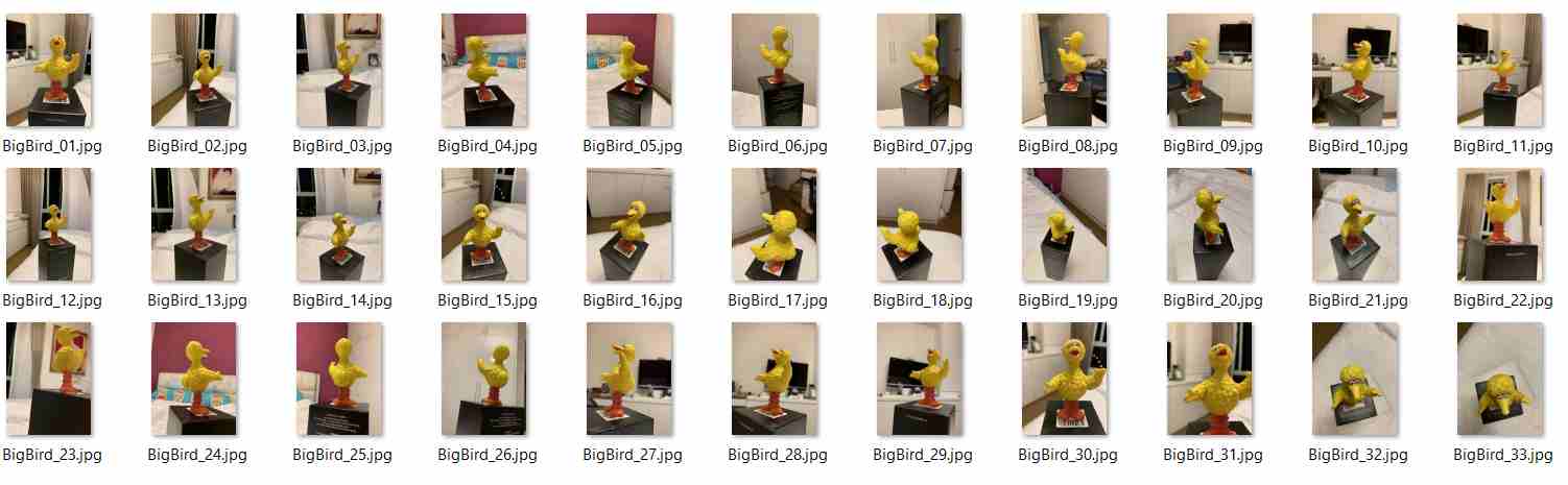
I tried taking 33 high resolution photos around the object and upload them onto Recap Photo Software to try again.
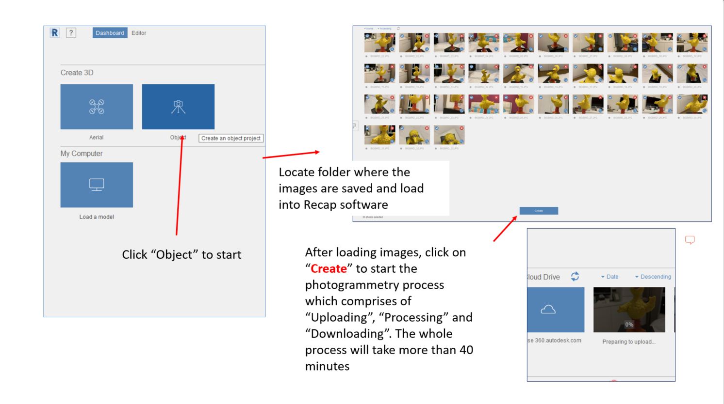
The process is straightforward following the instruction prompts by the software. The image below summarised the process.
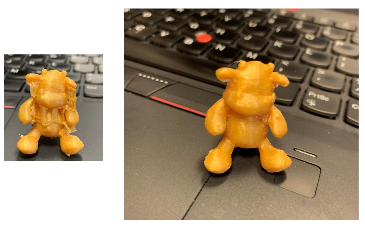
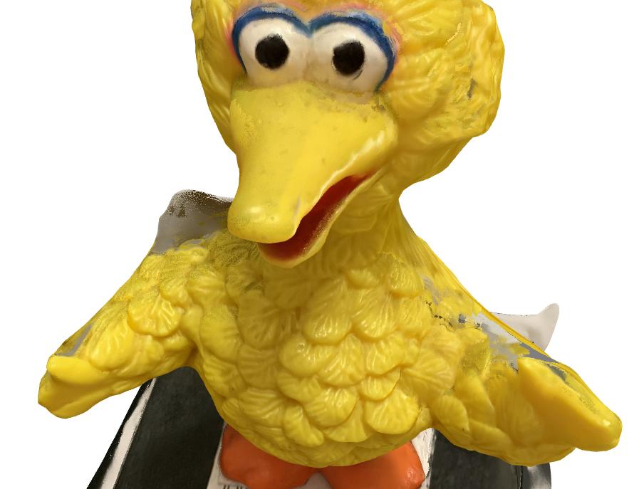
The processing took more than 1 hour 40 minutes but the result was satisfactory as shown below. The 3D file (*.rcm) is a large 22.3 Mb and hence is not included here.
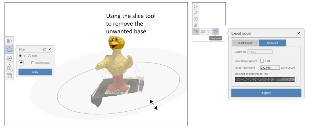
After the photogrammetry process, the 3D image still requires editting before it can be used for generating the stl files for 3D printing. This can be done using the built-in slicing function in Recap Photo software. The editting function is available in the toolbar on the left. After editting, the file can be exported as OBJ or STL fo 3D printing, again by selecting the export button in the toolbar on the left. The process is summarised below.