Exercise 3 - Computer Controlled Cutting 13/2/2020 to 19/2/2020
There are 3 tasks for this current week:
- Use the vinyl cutting to produce a sticker for laptop.
- Determine the optimum setting (Power, Speed and Frequency) for a 2-D laser cutter for cutting different material of varying thicknesses
- Design and make a press-fit construction kit
Task 1: Use the Vinyl Cutter to produce a sticker for laptop
After going through the tutorial on the FabAcademy.org website, I learnt that the vinyl cutter uses a computer-controlled blade to cut out shapes designed using vector graphics. Additionally, the vector image must only be lines with no fill.
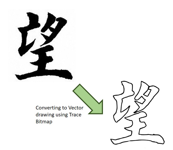
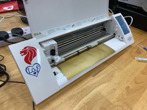
I loaded this image to the Cameo Vinyl Cutter
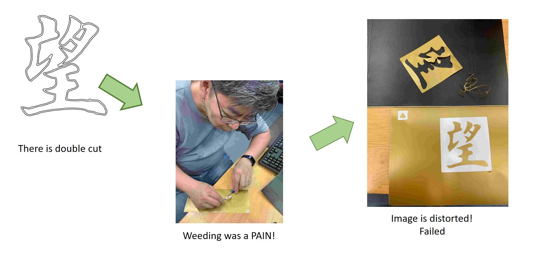
To my surprise, there was double cut around the image as shown in the picture below, and weeding it was really a pain.
I decided to create my image file from scratch again. This
time, instead of using "Edge Detection" option in "Trace Bitmap"
function, I used the "Brightness Cut-Off" option. After that I
use the "Fill and Stroke" function to obtain the final image
that has a line thickness of one pixel.

I used this file for the vinyl cutting and was able to get a
clean cut. After weeding, I applied the transfer tape and stick
the sticker on my laptop! Job Accomplished!
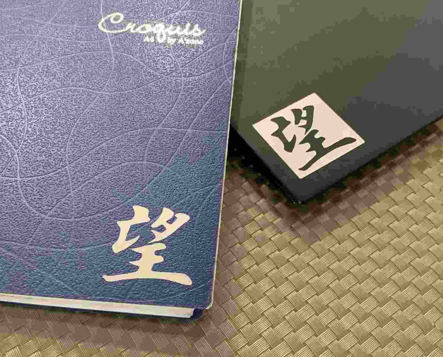
Chinese Character for Hope
Task 2: Determine the optimum setting (Power, Speed and Frequency) for a 2-D laser cutter (Group Work)
This is a group assignment done with Noel
Kristian and Yeo
Gau Siong.
Our collective work is documented on the SP
Fablab Website and hence only my learning
and reflections are documented here
What I have learned:
- about the relation between speed, power and frequency (PPI) and how it affects the results.
- the higher the power, the bigger the kerf
- for multiple passes, the speed for the first pass can be
slow, but for subsequent passes speed should be high to
minimize charring
- to position the laser head so as to minimize wastage of materials.
- to calculate kerf and use it to adjust the parameters of the model.
- about the difference between sketch and actual cut.
Task 3: Design and make a press-fit construction kit
Parametrical design
In order to make the press-fit construction kit, the learning from Task 2 must be applied. In addition, knowing parametrical design is of vital important as the thickness of the material that I eventually will work on may not be the same as what I based on when I develop the model in 3D software. Parametrical design will allow changing measurements according to the size of the cutting materials or design needs easily without tediously going into the "sketch" designs to change each dimension manually.
To understand parametric press-fit construction and Kref, I
consulted my My local instructor, Mr Rodney. Mr Rodney
demonstrated how to draw a simple parametric press-fit 3D box
using Fusion 360. After his demonstration I tried using Fusion
360 to create something similar and my learning journey is
documented below:
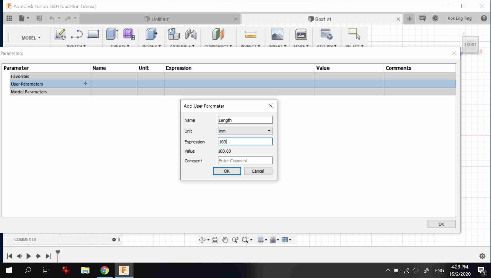
The first step is to setup the parameters for the model by going to "Modify" then "Change Parameter" to enter parameters such as Length, Width and Thickness.
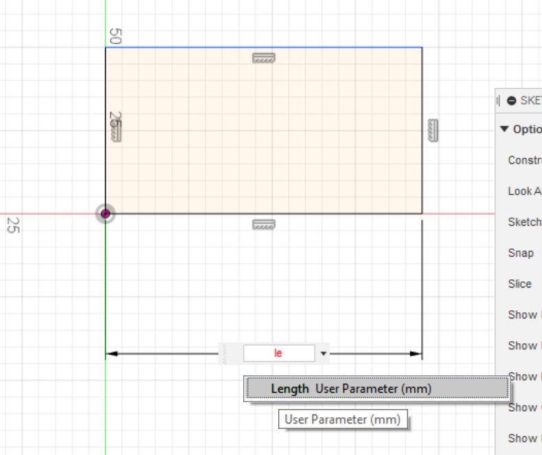
After setting up the parameters, to use, the dimension ('D" button) function is first activated, but instead of entering the values, the name of the parameter (such as length) is used.
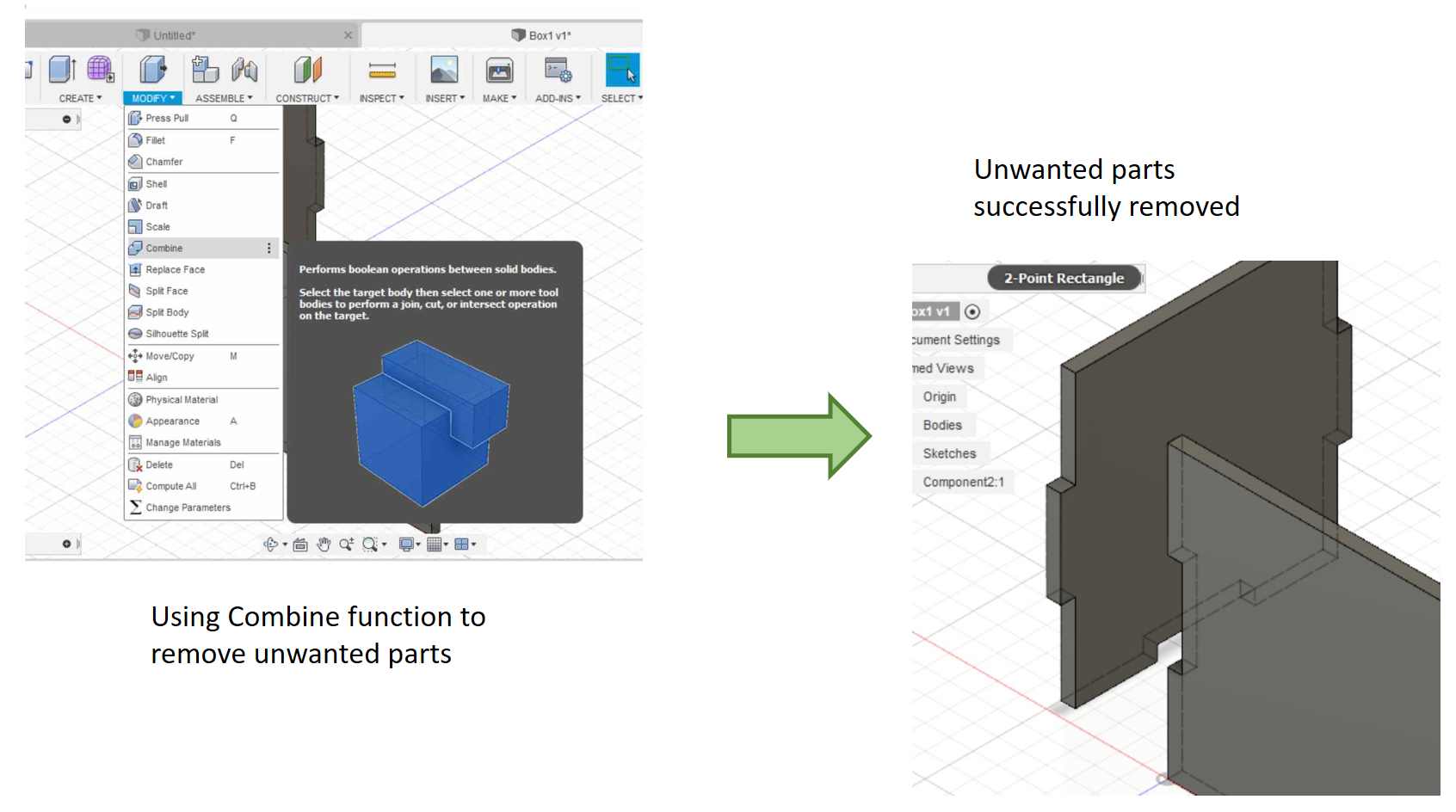
After drawing 2 sides of the box, I used the combine function to remove the unwanted parts
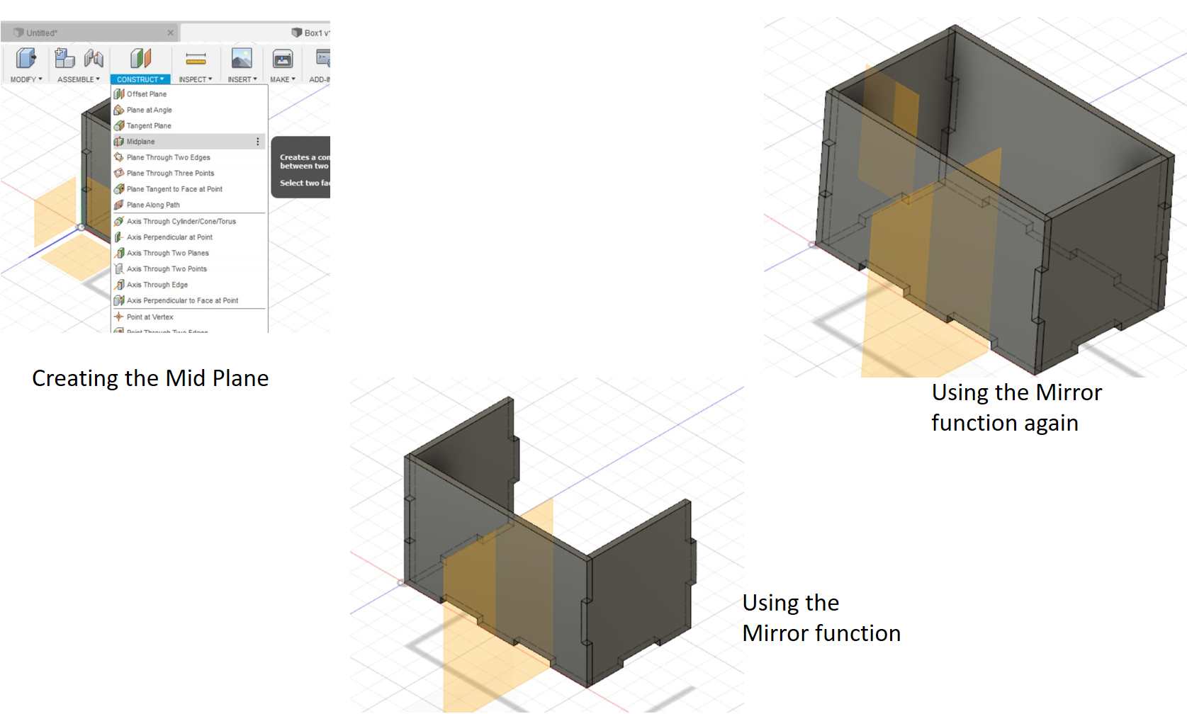
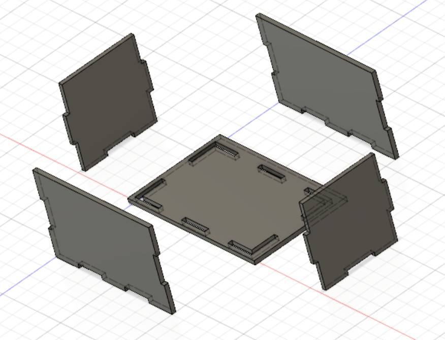
This is a screen capture of the completed box.
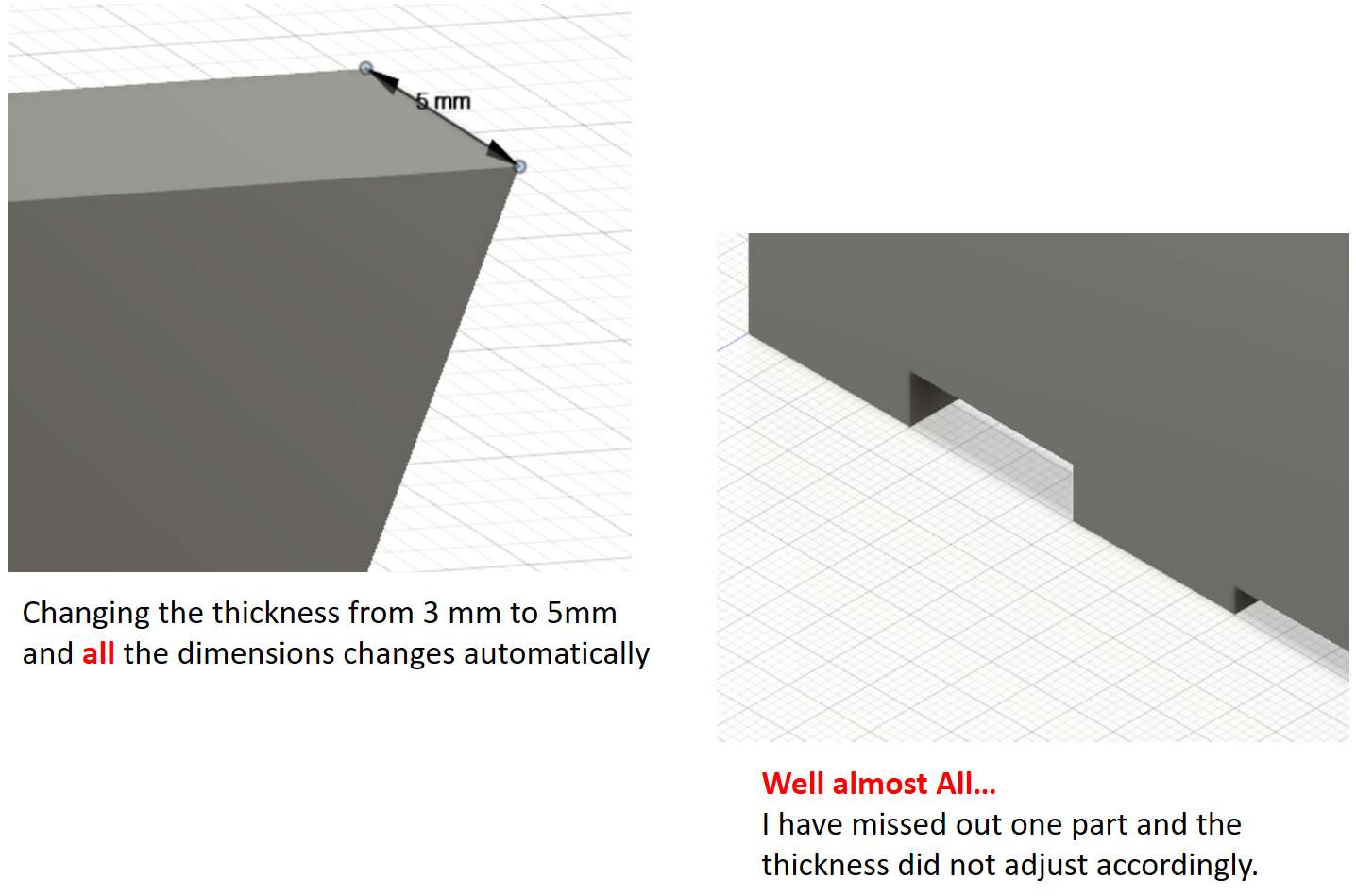
After modelling the box, I tried to change the thickness of the material (under change parameter in Modify)
Click to download Fusion 360 file
From the laser characterization study, the kerf for plywood is 0.05mm. As the plywood material I planned to use is 2.4mm, I used "modify paramter" and adjusted the "Thickness" to 2.3mm.
For the construction kit, the requirements are:
- Press-Fit; no glue is allowed
- Can be assembled in several ways
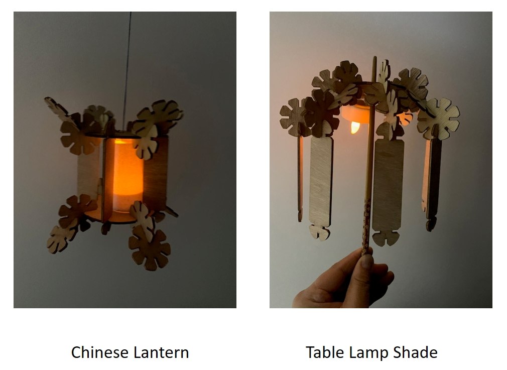
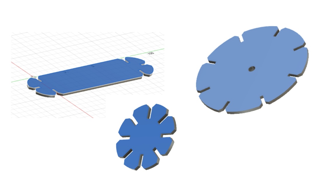
I planned to design a construction kit that can be assembled into several lamp designs. I created 3 different parts using Fusion 360 as follows
The DXF drawing files are as
follows:
Download the Fusion 360 fies here:
After saving the file, I started the laser cutting on the Universal laser system. I realized that the so-called optimum setting that we obtained from the characterization study cannot consistently produce good cuts. After consulting our local coaches, we realized that quality of the plywood can vary from batch to batch and fine-tuning is expected before every run especially when we are trying to produce press-fit models. I have to adjust the laser power from 70% to 75% before all the parts can be smoothly cut out.
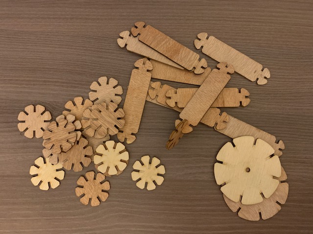
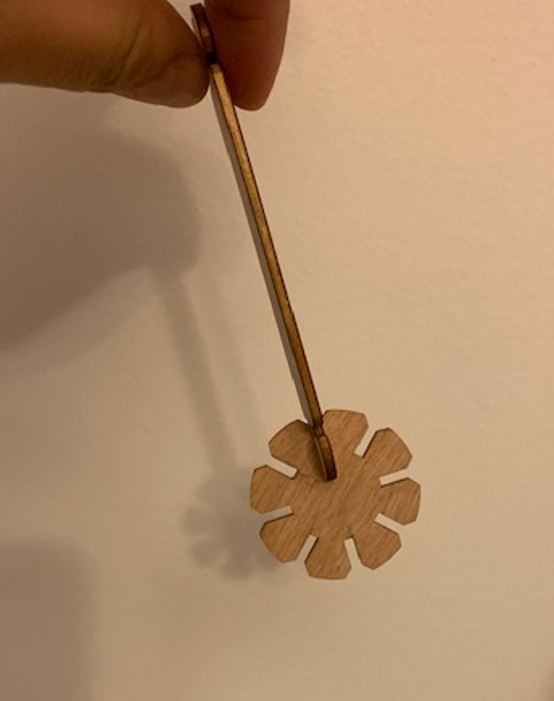
These loose pieces can be assembled in numerous ways to make for example a Chinese Lantern or a table lamp shade