I tried to finish all the setup and start milling, but it didn't work.
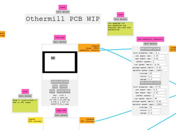
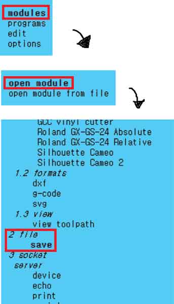
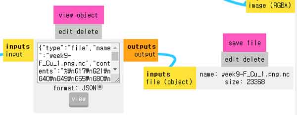
I had to find a new way and decided to save the setup as a G-code file and operate the machine.
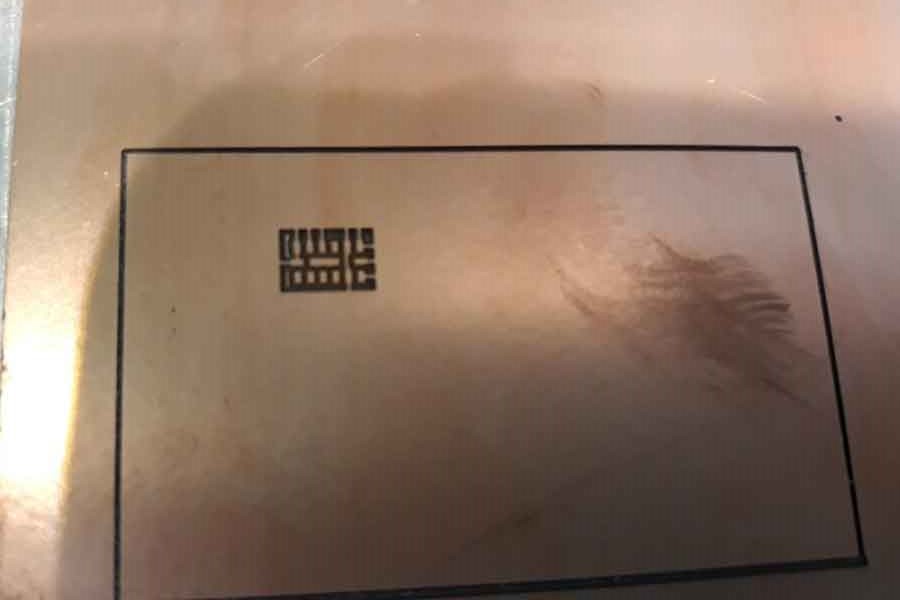
I tried to mill the 0.1mm end mill part first.
I thought it was neat, so I milling the rest and making the "first" board.
The sensor seemed to have been soldered well, but I burning to attiny85 while soldering
I tried to save the board, but things got worse.
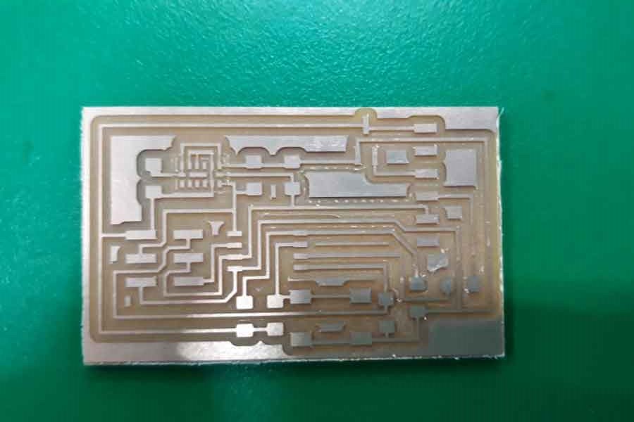
So I failed the first board and made the second board.
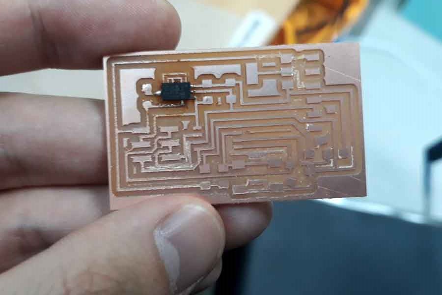
The second board was good for sensors and everything was good.
I couldn't take a picture of the completed board, but I tried programming..
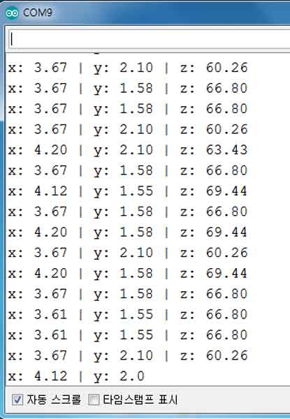
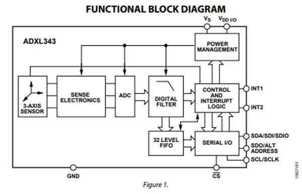
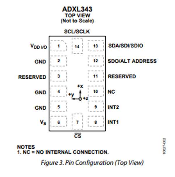
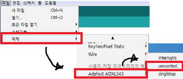
I downloaded the ADXL343 library from the Arduino Library Manager and ran the example.
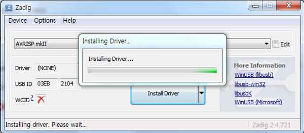
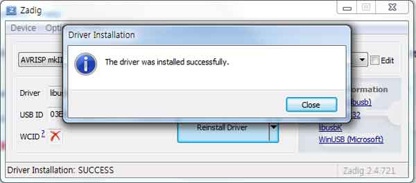
I installed the driver with Zadig to use AVRISP in Windows 7.
The programming was not uploaded to the board and the problem was that a voltage of 3.3V should be inserted, but a voltage of more than 4V could be identified.
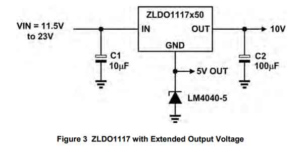
The problem was caused by the use of a 0.1A regulator, which should have used more than 0.3A regulator.
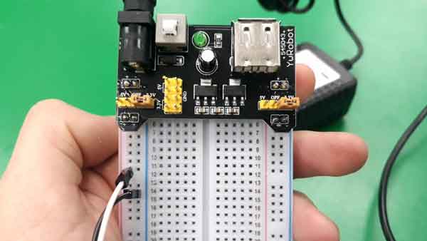
Remove regulator and re-program the board with a voltage of 3.3 V using YwRobot Bradboard Power Supply.
Programming was uploaded intermittently due to poor connection between 6pin header and Attiny85.
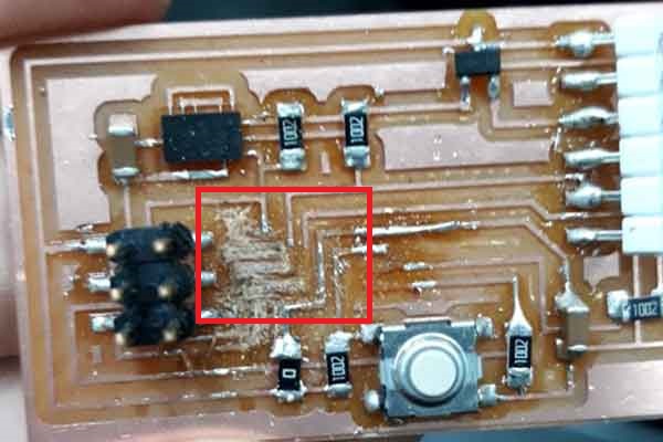
My greed is endless, and I repeat the same mistakes.
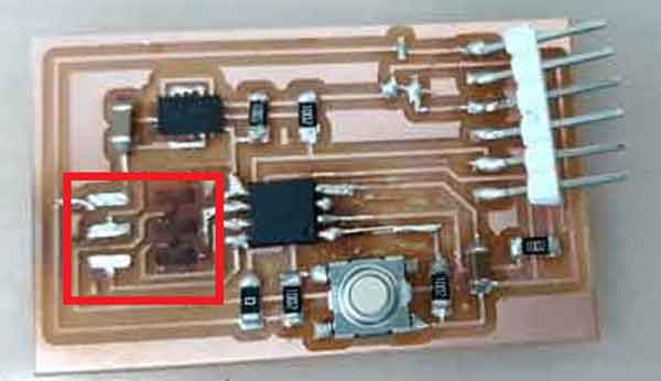
I wanted a clean connection, so I had to do soldering again, and then I burned the board Disaster.....
I decided to make a third board to solve the regulator problem.
The sot223 regulator was 1A regulator, which was larger than the 0.3A I needed, so I was able to solve the problem.
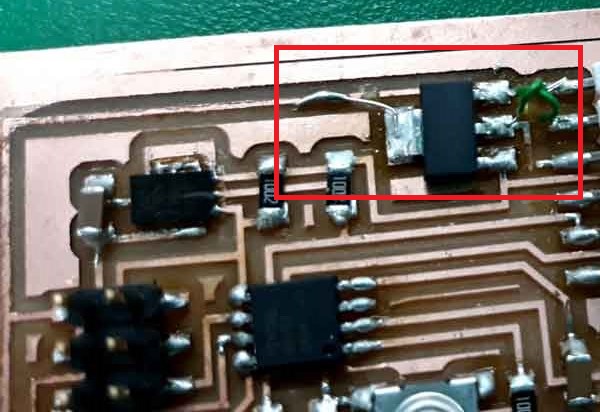
Smoke came out of the regulator when I made a board and connected it to a laptop.
I checked with a multimeter and GND and VCC were connected.
I soldered it again and connected it to my laptop, but the regulator burned again.
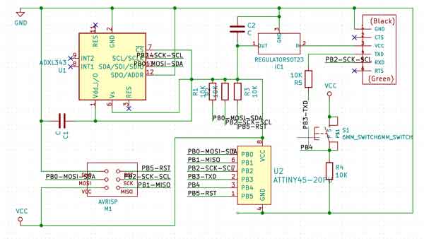
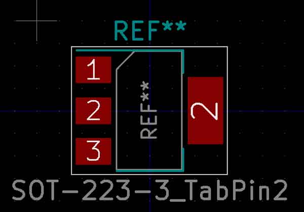
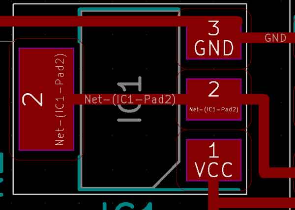
I looked up the pinout of the sot223 because I don't think it's a connection problem.
The footprint I used was different from the pinout of the actual sot233.
OMG... I was connecting GND and VIN in reverse
I cut the board connection with a piece knife and used a wire to solve the problem.
However, I tried to connect the board from my laptop to see if the sensor had a bad connection, but I couldn't find the board.
I made the fourth board but In the process of connecting the sensor, the vcc and gnd were connected.
I used all the available sensors and I was Despair
.jpg)


