Milling
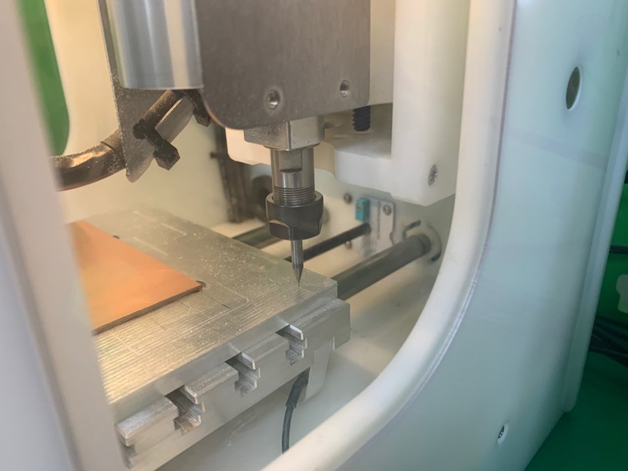
I used the Bantam CNC in the fab. Bantam has three removable windows and can have a collet and spanner attached. It can use Bantam tools or fab mods for software.”
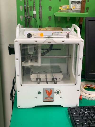
This machine is Bantam. I couldn't believe it was a CNC machine when I first saw it.
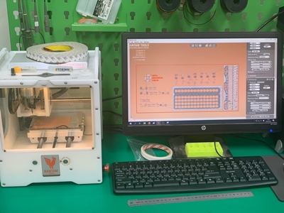
This is a picture taken with Bantamtool. It is built so that you can see the PC and the manufacturing pad together.
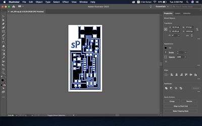
I took a PNG file from the tutorial, filled the place where Cooper was not needed with white through the illustrator, and initialed the SP from Seokpa.
I also received interior PNG.
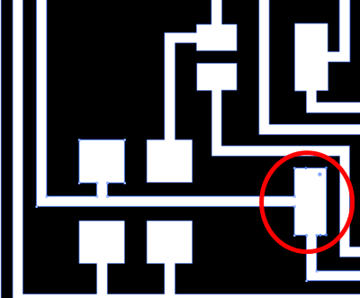
In the illustration, all paths were not recognized by BAntamtool. There was a sign on the screen that the black part was too thin to pass. So I stretched the black part, or the cutting part, a bit so that the software could read in the illustration. The red part did. Sections smaller than the end mill size in the Bantam tool could be identified by a red mark.
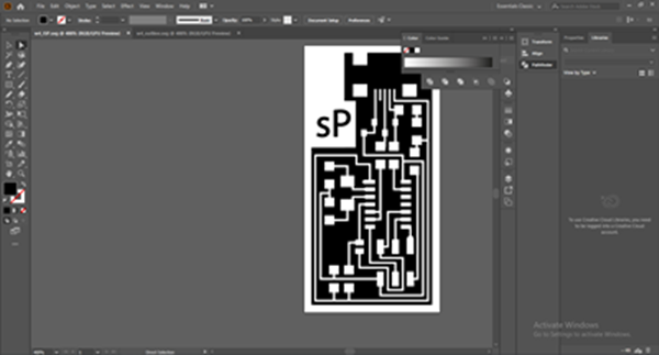
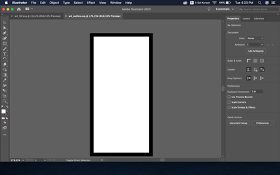
It looks like the final illustration and removes the white part from the background and leaves only the art board and the black part.
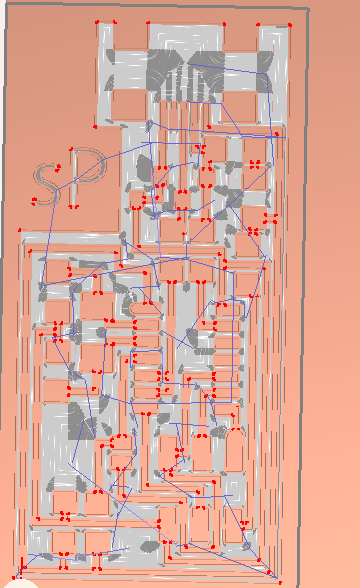
This shows the progress of the work at Bantamtool. The red part indicates that it is impossible to milling, but what is shown here appears because it cannot be made vertically. Because end mill is round.
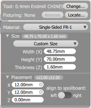
A window that sets the size and location of the material in the software. X: 12 mm Y:12 mm in the placement was entered because the metal was made to fit the vertical in the bed.
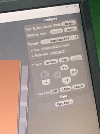
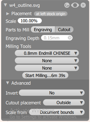
This window shows the setting value to cut the PCB board with an end mill of 0.8mm.
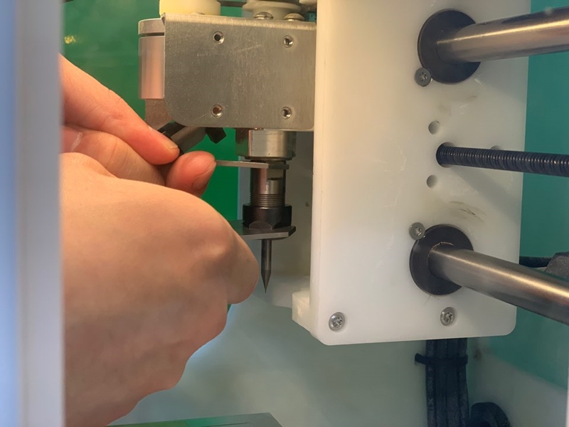
The end mill is set at 0.04mm. I used 0.04 before cutting after Engrave. And when securing end mill with a spanner, it should not be too weak or too strong. Secure with proper force!
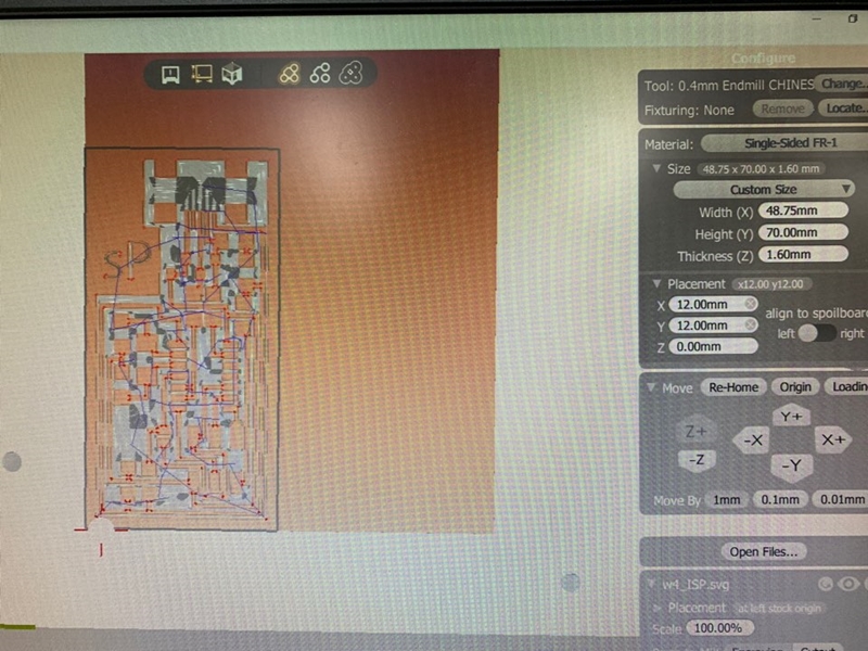
Shows the path of the final Batamtool and where the end mill is located. Here you can check if there is a collision going off course in advance.
It is to create a Z-axis zero value for the end-mill. You can set the zero value on the bed and cut it by the height of the material.
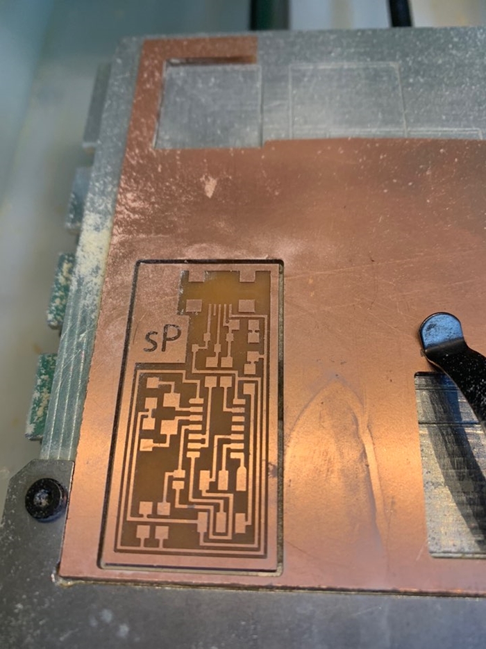
This is what it looks like after the engrabbing and Cutting. I felt good because there was nothing particularly wrong! :)
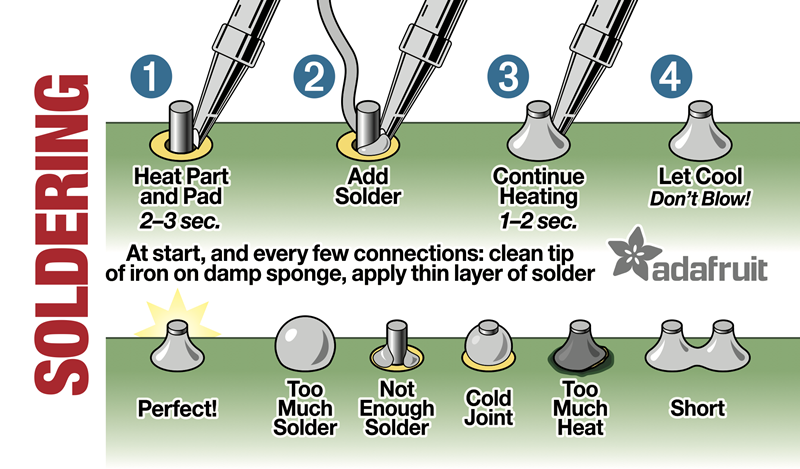
PCB Soldering
From now on, the order is to solder components on the cutting board. The point is to find the components in the tutorial correctly and solder it in the direction. Then you have to have a procedure to check if the current is flowing.
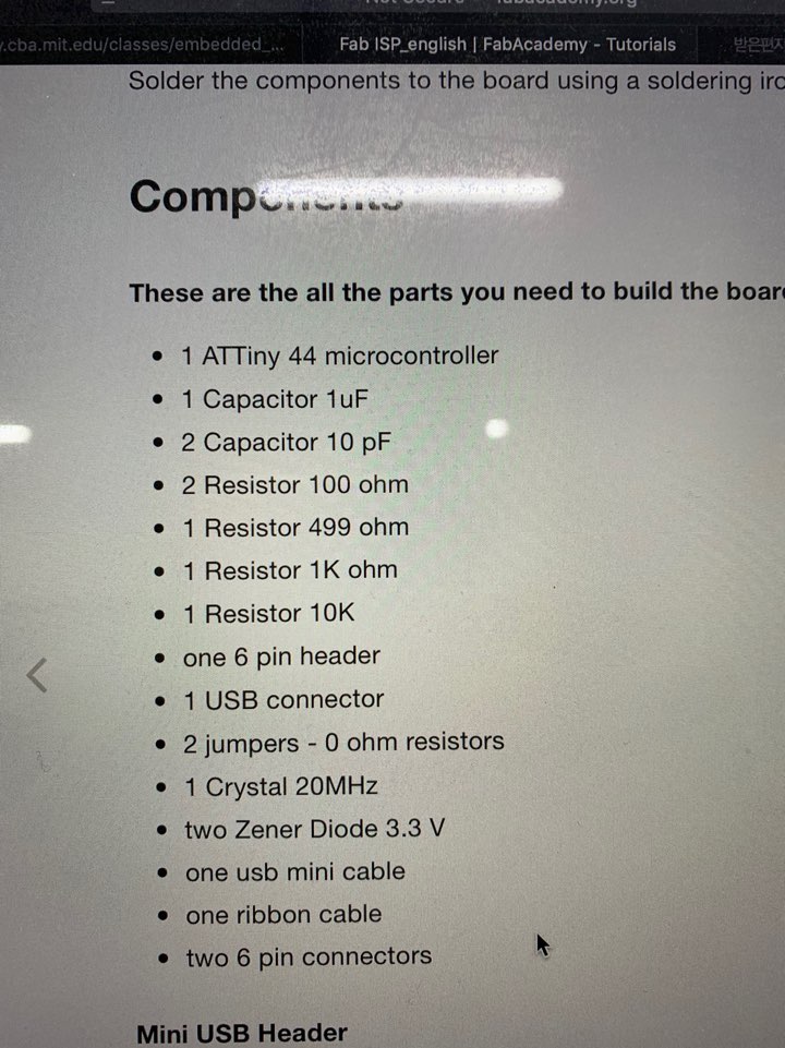
A list of each component. When I first saw them, I had to look for numbers because they were similar names.
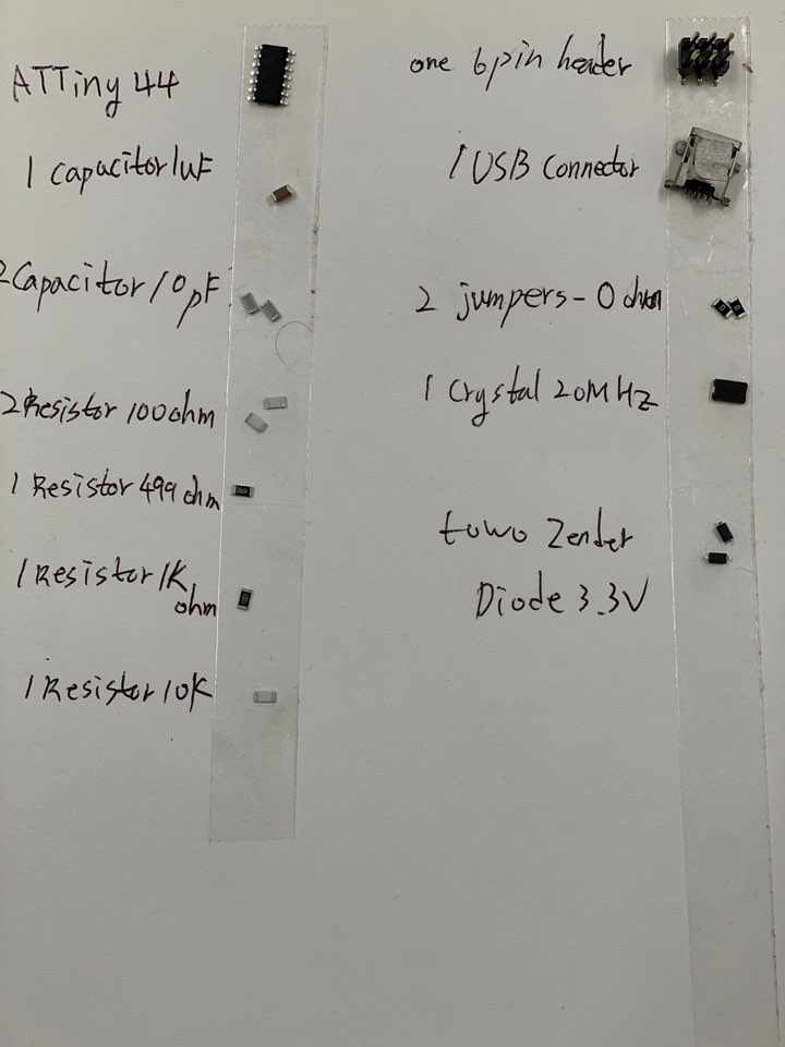
And since it's so small, it's better to attach double-sided tape to the paper and fix it while looking for it. Otherwise, you can lose it. It may be 10 or 100!
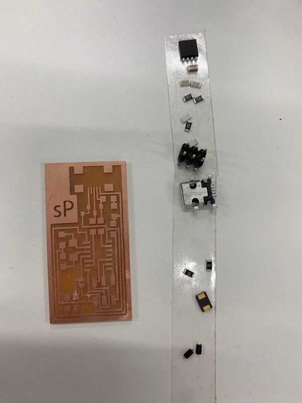
Check the number of components by looking at the board!
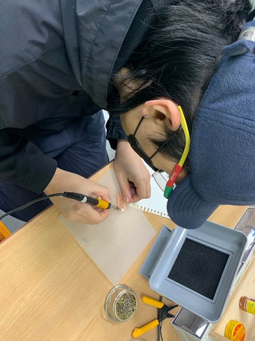
There is something to be careful about when soldering. Don't take out the pharynx too. Because if Cooper burns, it becomes unusable.
I didn't do as I said above! Because during the Regional Review, Saverio, the infrastructure of Shanghai, gave details on how to pay. So the picture before the attempt...
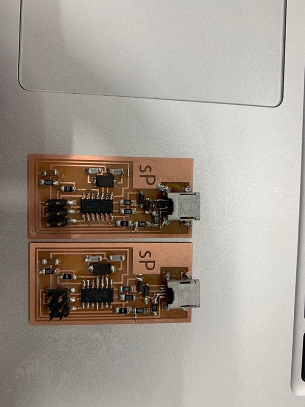
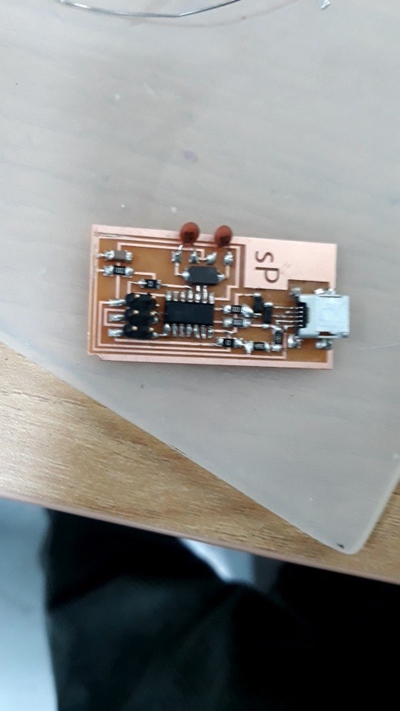
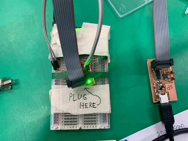
The picture above is the first board and the one below is the newly rebuilt board! I thought I was checking the flow of the current and going over without any problems...!!
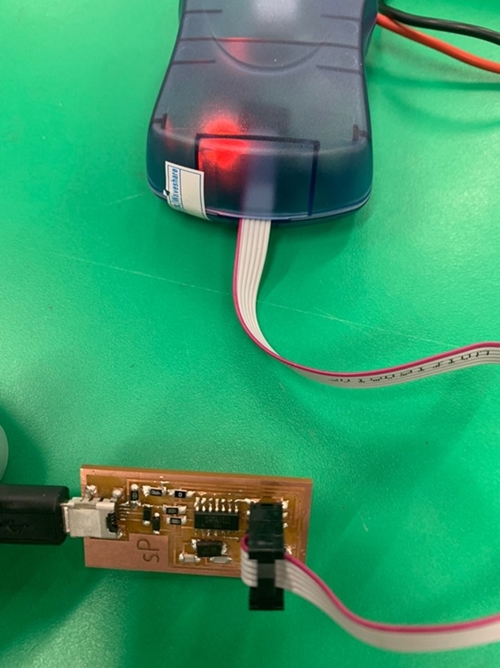
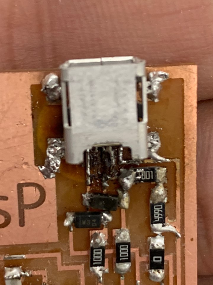
MK's machine checked the board's current flow, but... Red light means there's something wrong! So I rechecked it. over and over and over and over and over again. And I found that was Red Light shows no normal voltage flowing on the board.
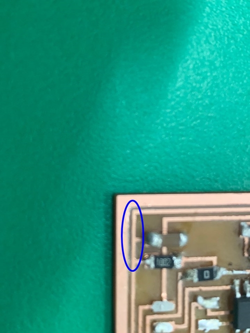
Craig of Seoul Innovation Fablab found out a problem with my board. That's where the Cooper on the board was supposed to fall. So where it should not work, there was an electric current going on So I cut out the part of the picture with a cutter! :)
Then the green light turned on!!!!!! At this time I made a noise, and I made a loud noise. I don't know exactly what you're talking about, lol
ISP Programming
From now on, we will work on building the possibility of programming in the board when there is no problem with the board! It's a part that sets the environment so that code can be read in the board, so you need to make sure it's typed correctly!

First, install the Xcode and prepare the necessary things.
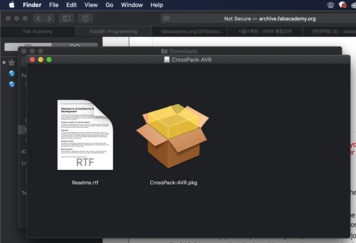
This is to install the firmware, but you have to specify the location of the firmware so that the next time you install the path through the terminal, you can make file, make hex, make fuse, make program. I can think of this as creating an environment that allows real programming to go into the board that I made.
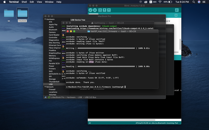
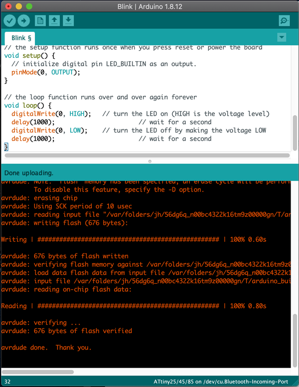
It looks like making hex, fuse, and trying a program at a terminal. Here, make fuse is often unsuccessful, but it was successful in one try! And make program made fuse and succeeded make program. Make clean command is a command to clean up existing code, and Make and make hex converts my .c code into a hex file ready for uploading to the attiny microcontroller. Make fuses sets the internal fuse on the chip. The fuses control important properties like the clock speed and EEPROM memory. Finally, the Make program is to install a program with ISP function.
http://eleccelerator.com/fusecalc/fusecalc.php?chip=attiny85
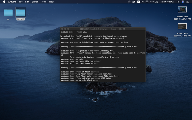
This is how the make program looks successful!
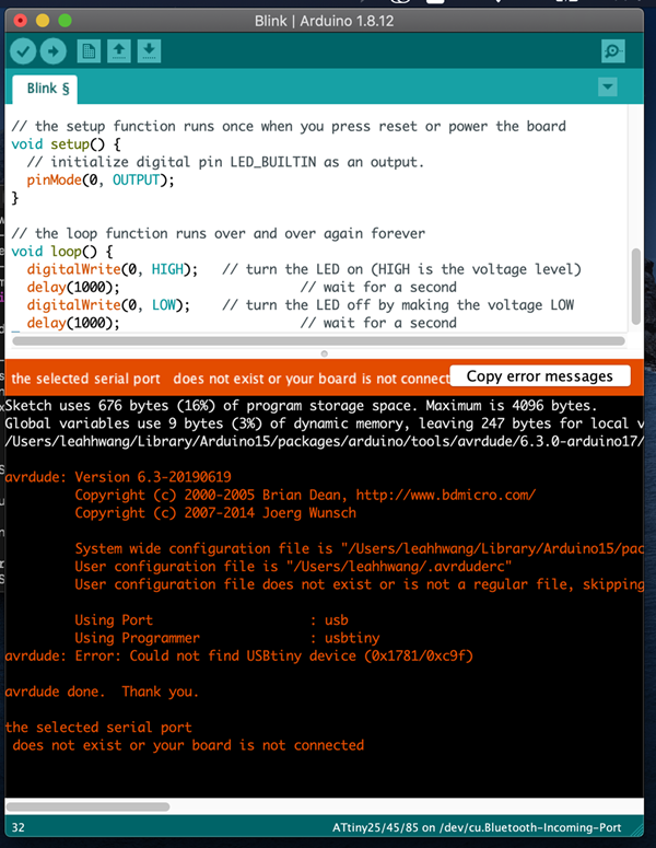
However, the following error occurred when trying to enter the LED color change code with aduino. This meant that there was no problem with the port, but there seemed to be something wrong with the board.
The reason why I had to make a new ISP was because the trace of the milling board was not clean before soldering, so I had to milling again because it seemed that there was a connection problem such as VCC GND. And the reason for most Arduino port connect failures is that there are 6pin pin-out problems (connections in semantic are changed in board design) or sometimes not connected in MAC or window10
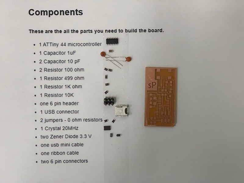
Before soldering, we checked the components and their values again. This is image from here : Link
Thanks!
This time soldering went well. For most VCC GND issues, the amount of soldering should be adjusted well, as it is often connected by trace connections or excessive soldering. And it is also good to check in advance with a multitester to see if the trace milling is working well.
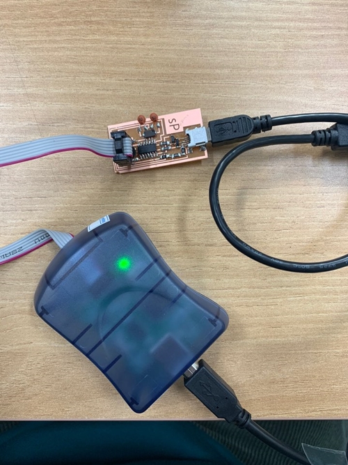
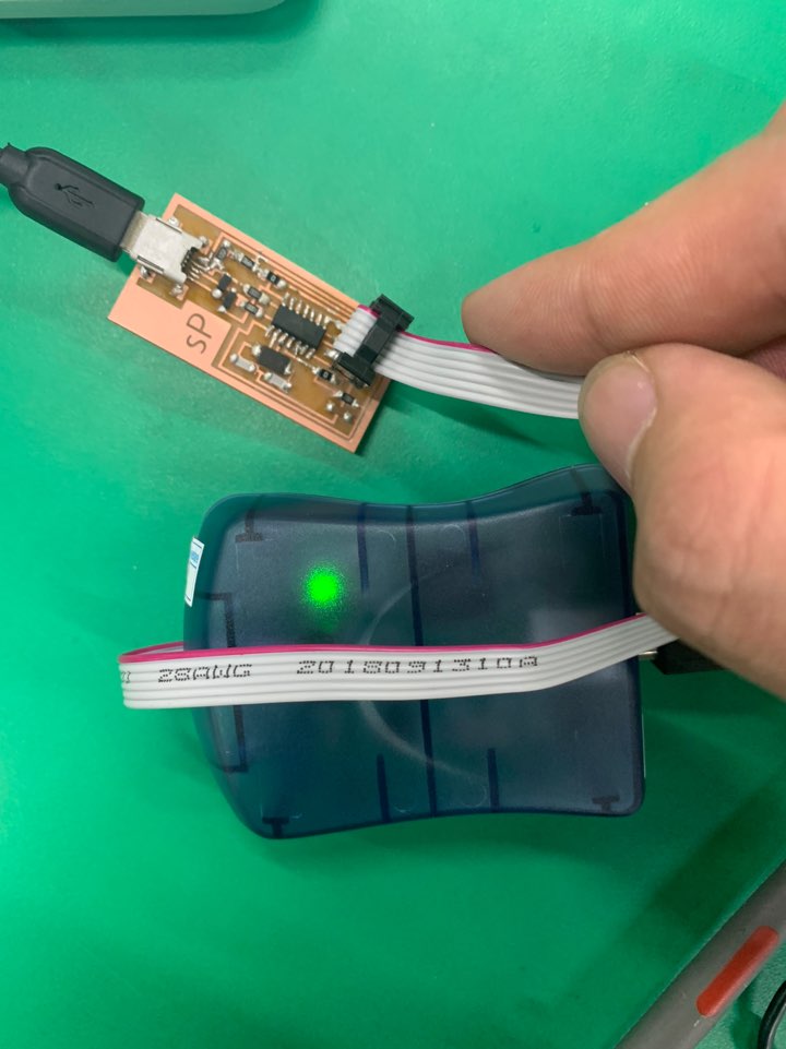
This time, Green Light came out. Normal voltage is flowing on the board.
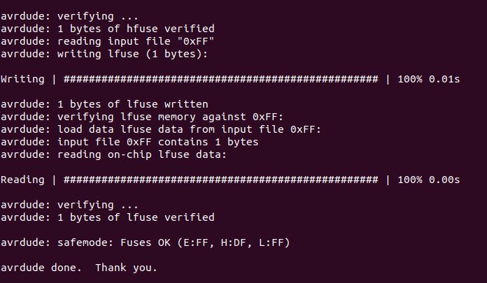
Because the green light came out, the make hex, fuse, program succeeded.
After removing the jumper, I uploaded Arduino's LED light change code.
I could change my color to green!