Use OLED Display
IThe OLED display uses field-lighting phenomena that emit light when current is applied to fluorescent organic compounds. Shine on your own! It's a self-illuminated device.Therefore, backlight is needed and is used for marking and text.
This week, we developed ESP12E board and tested OLED display. It was also a week that helped me understand I2C networks.
Here is OLED library : : Link
https://github.com/adafruit/Adafruit_SSD1306
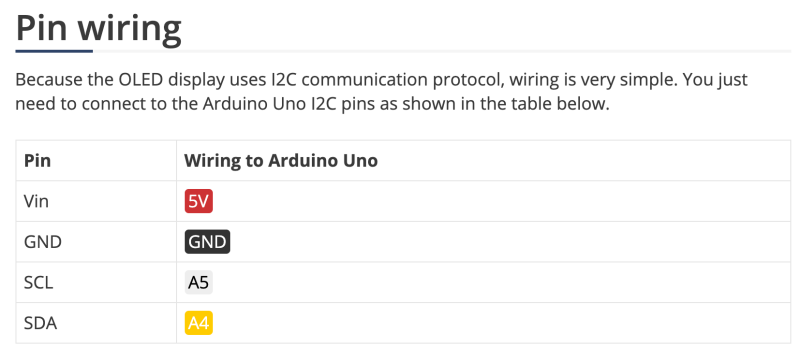
First, we looked at the pin-out of 0.96-inch OLED DISplay. It consists of VCC, GND, SDA, and SCL with four pins.
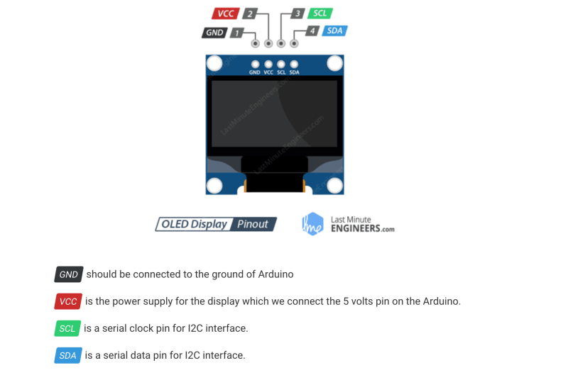
The following is a description of the pin. VCC requires 5V and SDA and SCL are I2C interfaces.
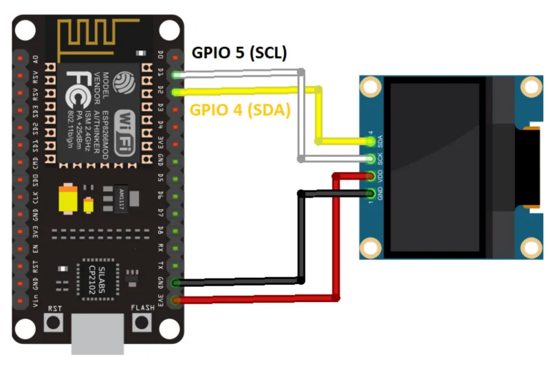
This is an OLED that is connected to the Node MCU1.0(esp12e) board. Connect to the GPIO number.
ESP12E Board develop
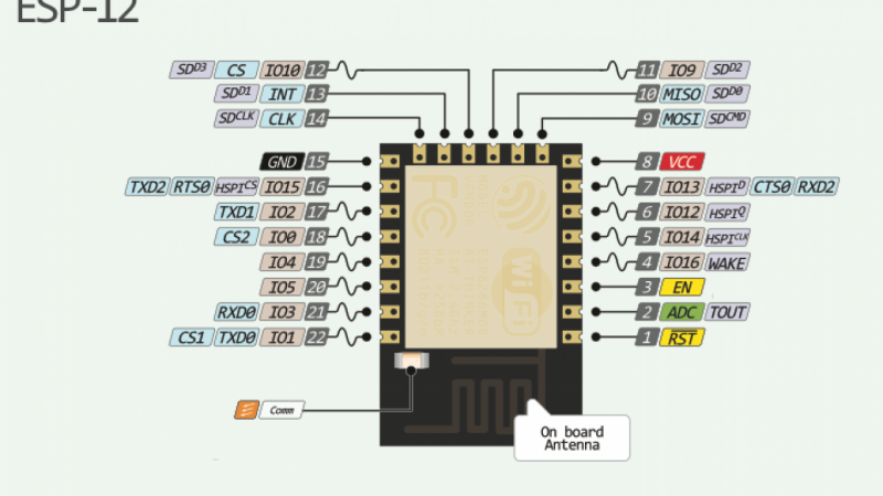
It's a pinout for Esp12e. Esp12e also has a pin for SPI, so I can test it for my final project.
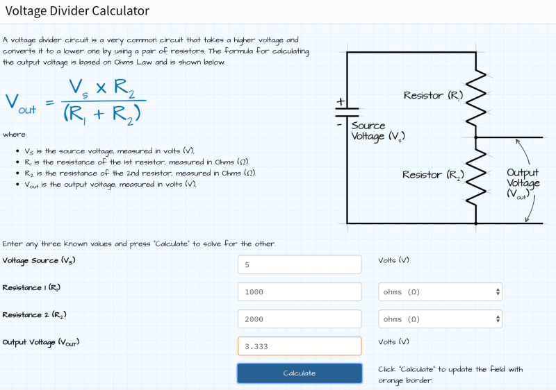
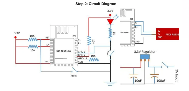
And FTDI in our lab has only 5V, so resistance was needed to lower the voltage of the TX according to the Voltage Divide. The voltage required for Tx/Rx was 3.3 volts, so a total of 3K resistance was required.
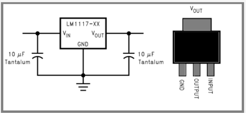
And because ESP12e MCU requires 3.3v, it had to use a regulator to reduce the voltage of 5V to 3.3V.
LM1117 3.3V 1A regulator was used and the capacitor was needed on both sides, so added.
The reason for using 1A (1000 mA) is that more current will be needed depending on the output device (if using WIFI, only about 600 mA of current will be consumed).
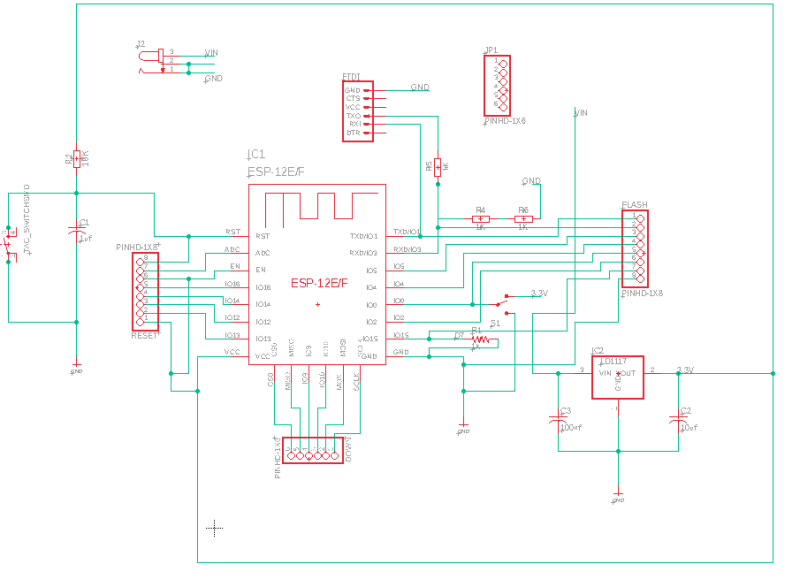
The following is the semantic that I designed. Esp12e requires a flash button and a reset button, which requires the same 3.3V and can be programmed at HIGH. So I chose the slide button.
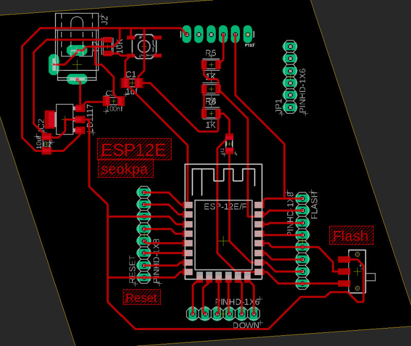
It's board design. The design rule is designed with a minimum of 0.42mm.
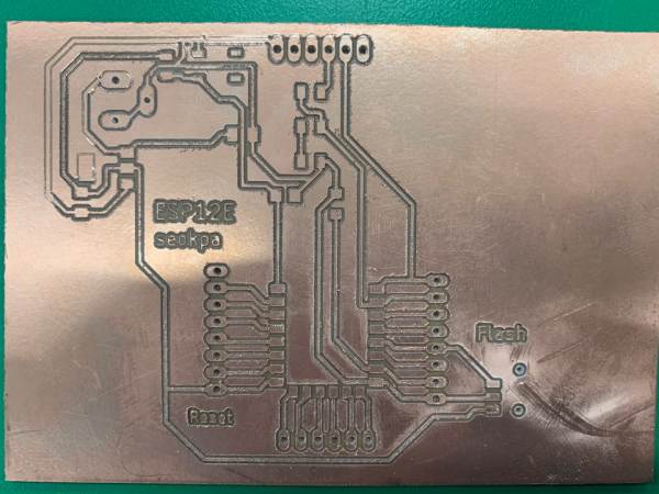
This is what it looks like when I was milling. The top was not well milled, forcing me to draw the line manually. In particular, you should check if the VCC and GND are connected. Without checking, I connected the power and rode the regulator once....(Thankfully, the ESP12e didn't burn.)
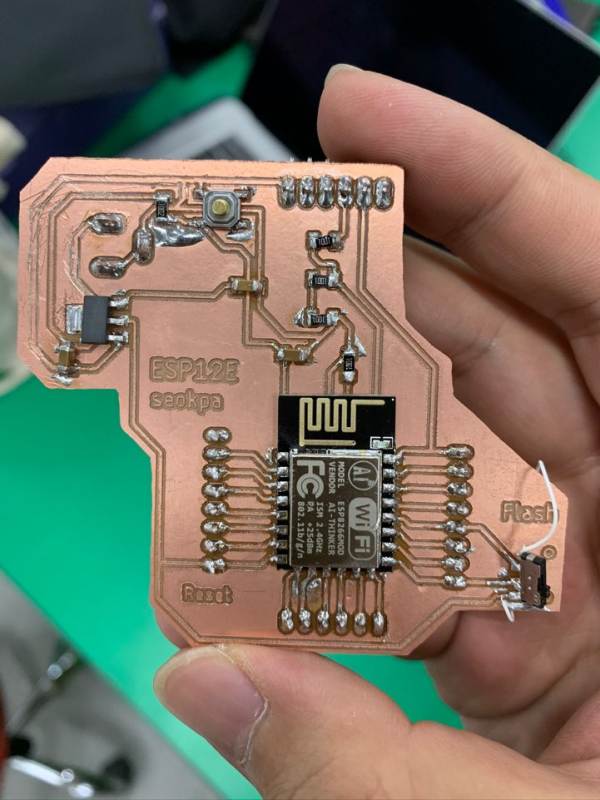
It's a completed board. I thought it was neat and good soldering, but there were many things I overlooked. The pinout of the slide button changed the direction of the VCC and GND, so I used a jumper.Then the direction of the Con-jack changed, cutting and soldering the GND.
The above semantic corrected the following problem and redesigned the design.
The problem is that the ESP12e must be connected to the Enable pin and the VCC (3.3V) to operate the board.
I heard that the reason why it was made like this is to reduce power consumption with the chip is not in use.
If so, I thought it would be good to try designing with buttons.
After connecting the Enable pin to the VCC, the coding was uploaded... The output didn't come out.
Here is how you upload code to the ESP with OLED display. : Link
Arduiono IDE Code
#include#include #include #include #define SCREEN_WIDTH 128 // OLED display width, in pixels #define SCREEN_HEIGHT 64 // OLED display height, in pixels // Declaration for an SSD1306 display connected to I2C (SDA, SCL pins) Adafruit_SSD1306 display(SCREEN_WIDTH, SCREEN_HEIGHT, &Wire, -1); void setup() { Serial.begin(115200); if(!display.begin(SSD1306_SWITCHCAPVCC, 0x3C)) { Serial.println("SSD1306 allocation failed"); for(;;); } delay(2000); display.setFont(&FreeSerif9pt7b); display.clearDisplay(); display.setTextSize(1); display.setTextColor(WHITE); display.setCursor(0,20); display.println("Hello, haeri!"); display.display(); delay(2000); } void loop() { }
Display in code aboveprintln (""); You can modify the text in parentheses, and to refresh the screen, you can press the reset button on the board.In void setup(), set up a serial monitor and if you can't get the library on the display, it's coded to send a message. And you can set the display size, font size, and font message. Each command is displayed.setTextSize,display.println ("Hello, haeri!");
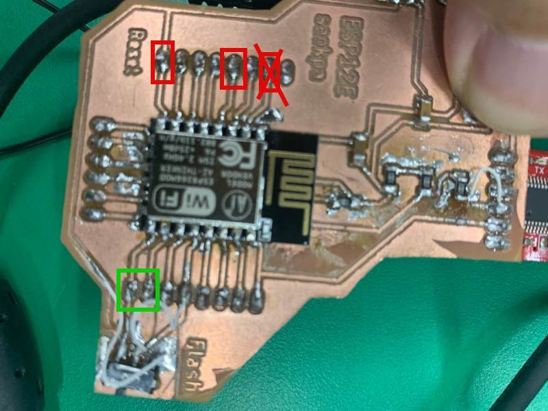
This photo shows that the Enable pin and VCC should be connected. You can find out the information by searching for esp12e mini physical in Google.
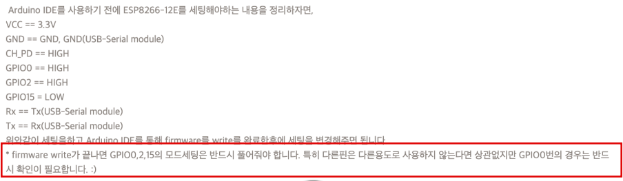
And finally, I found out on the Korean site. Esp12e was that the upload work had been completed and GPIO15 had to be connected to the GND. (This includes GPIO0,GPIO2,GPIO15 Pin.)
So I connected it using a jumper.Display in code aboveprintln (""); You can modify the text in parentheses, and to refresh the screen, you can press the reset button on the board.
Credit Link : Link
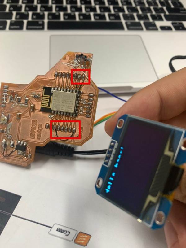
Esp12E is working! Hi haeri!
Here is OLED reference : Link
sch file : Download
brd file : Download
ino file : Download