Group assignment
Review the safety data sheets for each of your molding and casting materials, then make and compare test casts with each of them
Datasheet materiali
Before we started we read the datasheets of the materials we were going to use:
silicone rubber
and
polyurethane resin
In the beginning we used older materials to make tests and, after becoming familiar with the techniques, we used the same materials but new ones.
Cut 3D
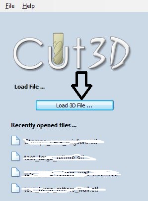
First we opened the Cut 3D software linked to our Roland and imported the file by simply clicking on Load 3D file and selecting the correct file previously placed in a folder on that computer.
Part 1
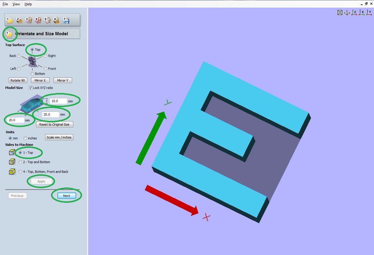
Once the file is imported, the program shows you the object and allows you to choose the orientation and size of the object. We have chosen Top and left the measurements set on OnShape (10mm x 20mm x 20mm). Sides to machine instead indicates which way the machine should start milling and also in this case we have chosen Top. Finally we clicked on Apply and Next.
Part 2
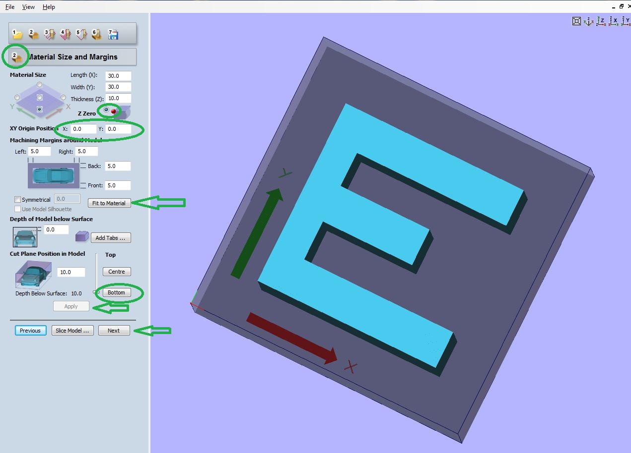
The second step allows you to set the material size and margins. We have set the Z at the top left inside the material and the x y origin position to 0. Initially we left the measurements of our object unchanged, but our tutor pointed out that this way we had no margin, so it would have been difficult to understand that that was an E! For this reason we added 10 mm in both size and length and pressed on Fit to Material; in this way the program evenly distributed margins of 5 mm. We didn't add Tabs because we didn't need them because ours is a mold. Finally we selected the depth to which the machine must mill by choosing Bottom. We then clicked on Apply and Next.
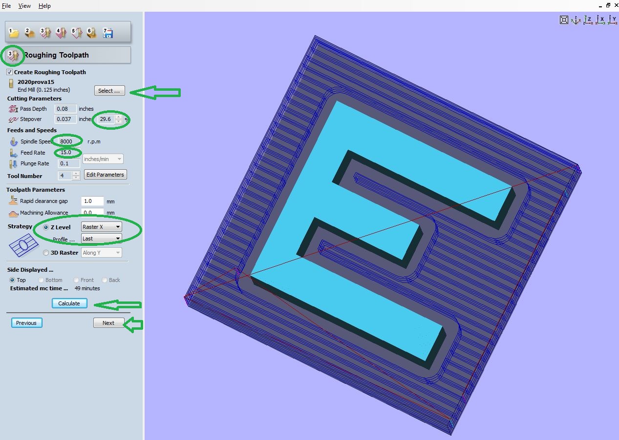
Part 3
On the third step we calculated the roughing, that is the first cut, the one to eliminate the material. The finishing, on the other hand, which we did not use because in this case not necessary, is used to define the details. We selected the tip by clicking on Select. Then we set the pass depth (which is the maximum depth at which the tip reaches in one pass) to 0.08 inch and the spindle speed to 8000 rpm. The strategy allowed us to compare two different cutting modes. We chose the Z level with raster X which would cut our letter well (like the 3d raster setting, but in less time). Once again we clicked on Calculate and Next to move on to the next step.
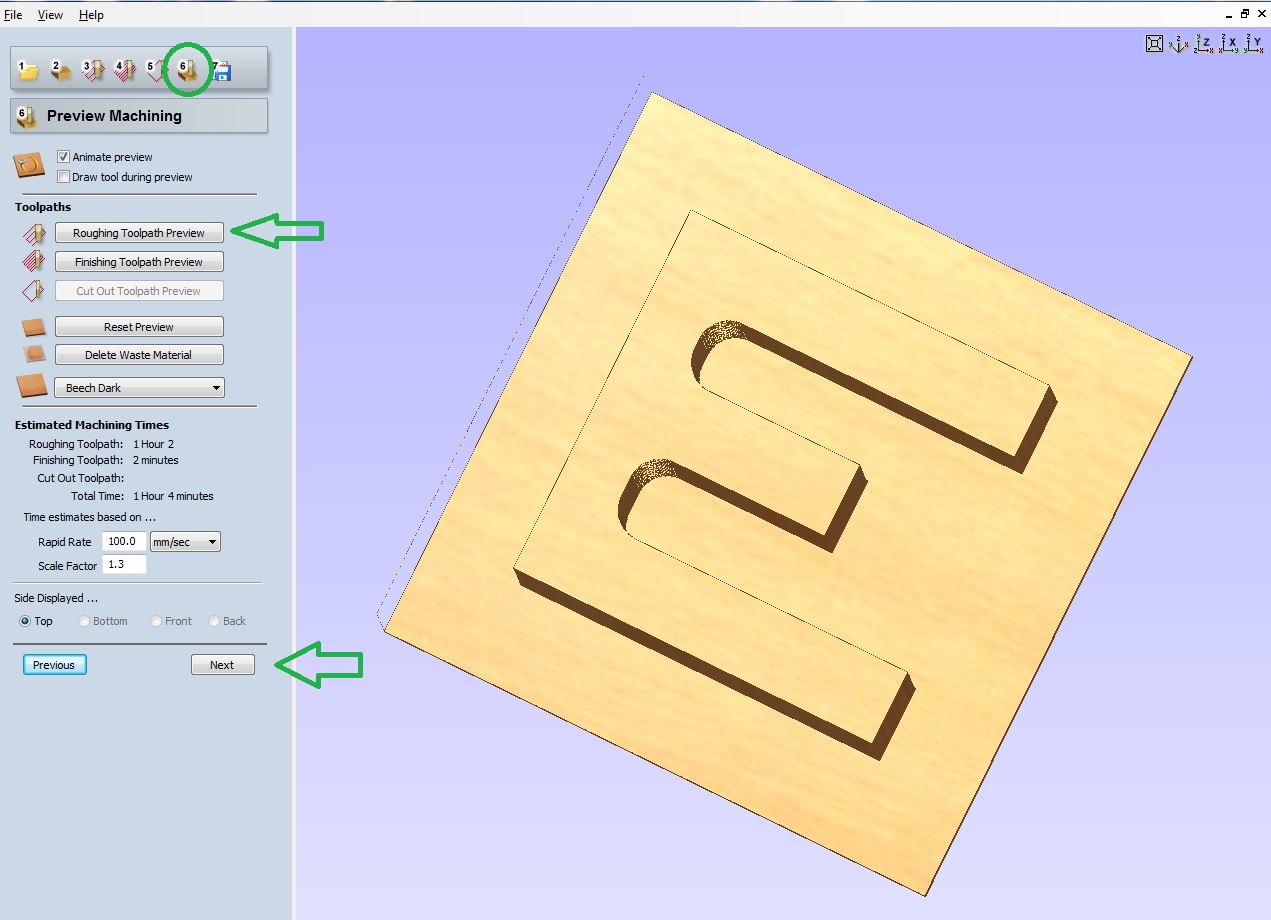
Part 4
At this point we could see the preview of the cut by clicking on roughing toolpath preview, setting the rapid rate to 15 inch/min and the scale factor to 1. Then we clicked on Next.
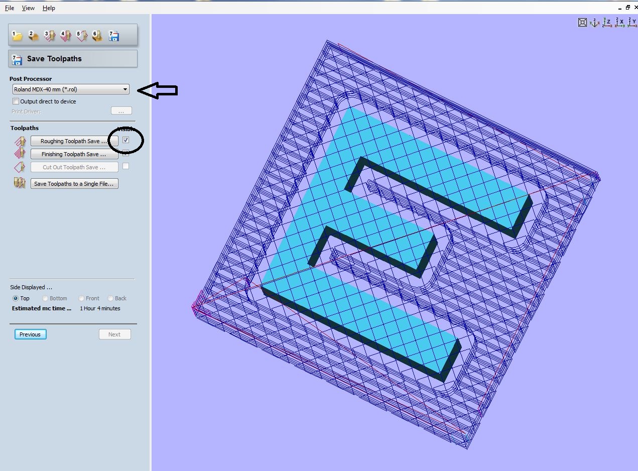
Part 5
To conclude: we have selected our post processor, saving only the roughing toolpath. Pressing instead on output direct to device we would immediately send the command to mill the piece.