Input devices
Week 09
Machines and Materials
Softwares
Group Assignemt
During this week we are going to be using sensors to measure something: add a sensor to a microcontroller board that you have designed and read it, in my case I have been working away from the lab due to covid so I will be using an arduino board to test my sensors. For the group assignment we will probe an input device's analog levels and digital signals.
Individual Assigment
Measure something: add a sensor and read it
I followed the next steps to my assignment.
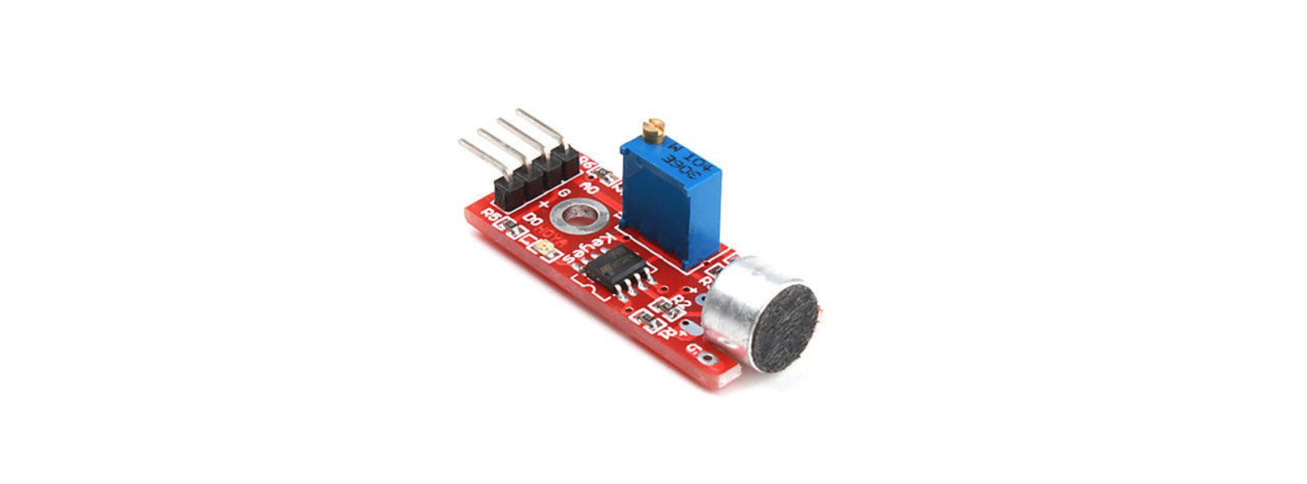
1- I decided to learn how to use the sound sensor, so I could use it for my final project.
2- I'll be using the following:
-LED
-1K Ω resistor
-Jumper wires
-Relay
-Arduino board and USB connector
Here is a small guide on how to conect the sound sensor:

3- Wire it, I used the following image as a reference but placed the relay between the led strip and from there I connect it to a DC power
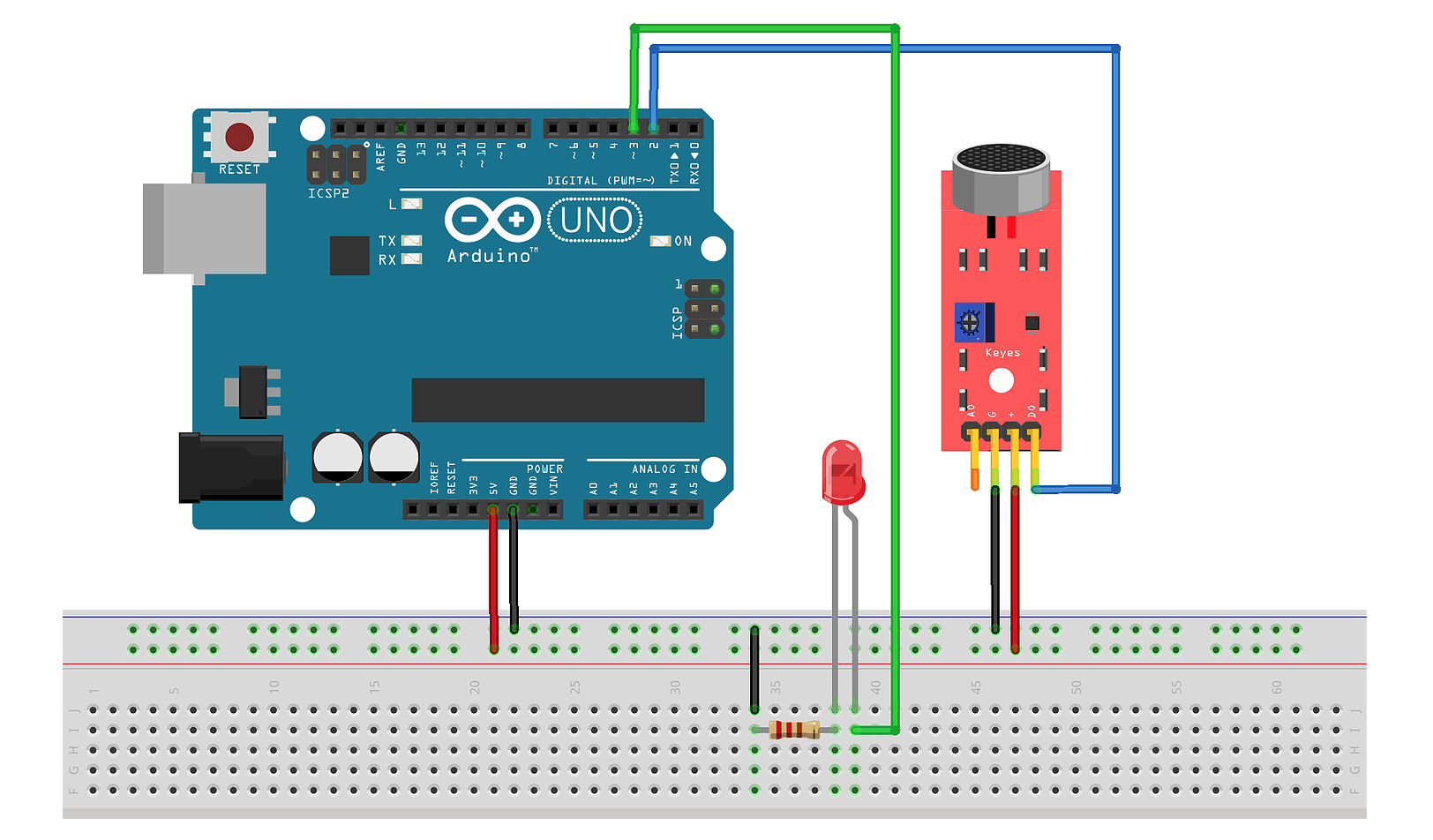
4- Connections:
Sound sensor G → Arduino pin GND
Sound sensor + → Arduino pin 5V
Sound sensor D0 → Arduino pin 2
Relay → Arduino pin 3
Relay COM → Led +
Relay NO → DC
Led - → GND
5- Program it
- The problems:
At the begginig I thought that the sensor, I had to adjust the sensitivity by turning the small screw on top: Clockwise = more sensitive, Contra Clock Wise = Less sensitive. Even after doing this I couln't manage to make it work, so I opened the "Serial Mononitor" in the Arduino software to read if there was any change in the value while making sounds. Adter a few adjustments it worked!

6 - This is how it looks:.