Electronics Production
Week 04
Machines and Materials
Softwares
Files
In electronics production for this we had to fabricate our own PCB (printed circuit board). The first design of the circuit board was provided by the Fab Academy team as it was an introduction to electronics production. For the group aasigmente we had to test the milling machine we have in our lab, Roland 50, and its tolerances and accuracy.
Group Assigment.
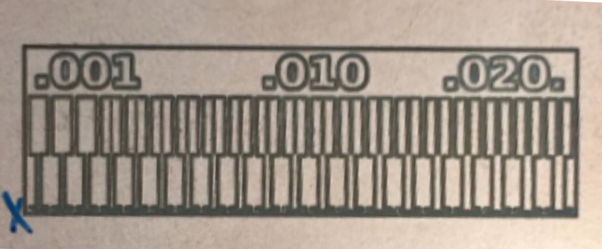
Aim: characterize the design rules for your PCB production process.
1- Go to: www.fabmodules.org
2- Click on input format and choose (image.png)
3- Select the image of the trace, click open.
4- Click on output format and select (Roland mill (.rml)
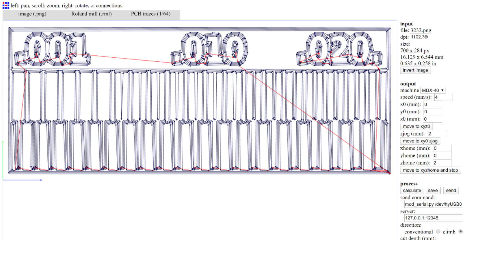
5- Click on process and select (PCB traces (1/64)
6- In the output section, change the machine option into (MDX-40)
7- In our case we changed the tool diameter to: .09 and Z home: 2
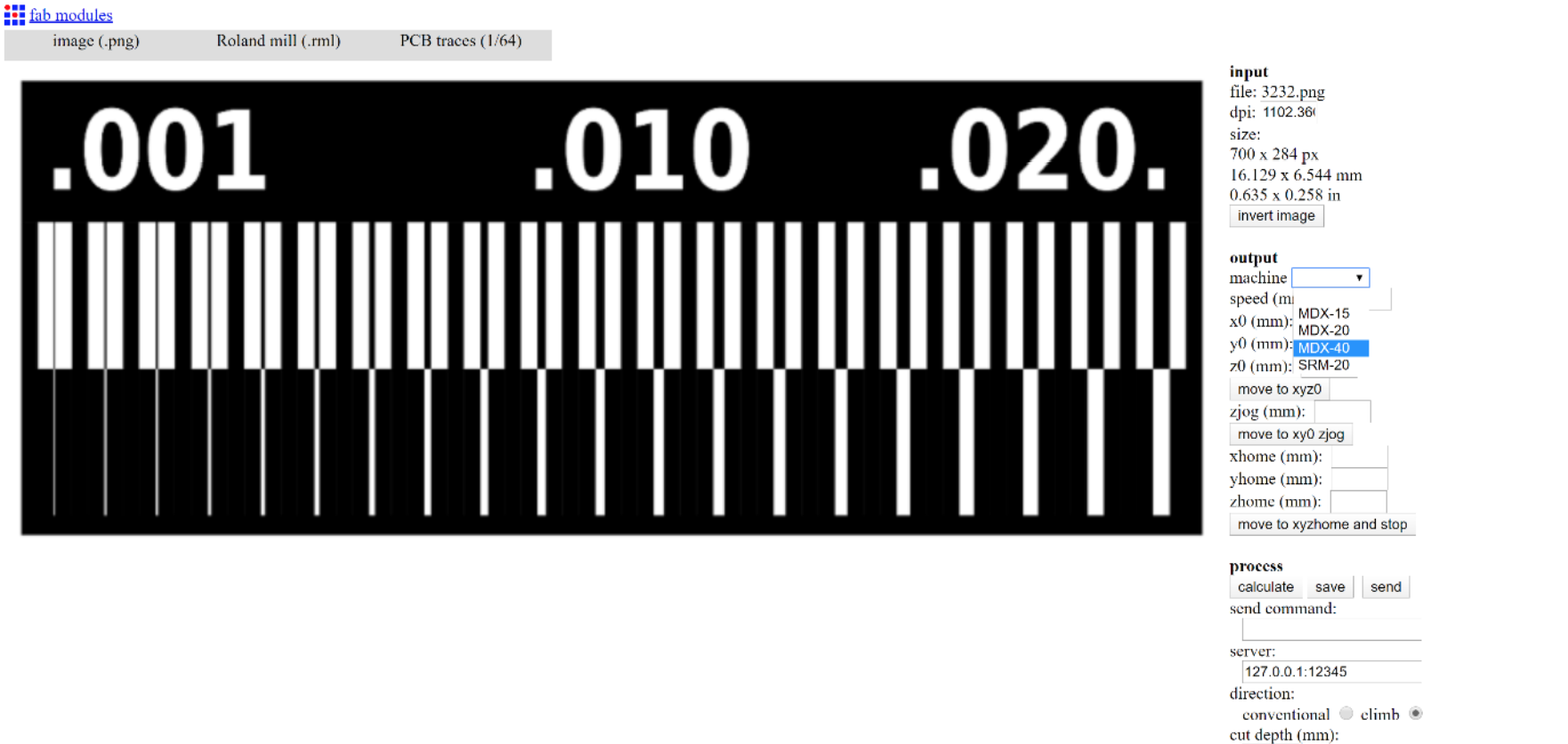
8- calculate:
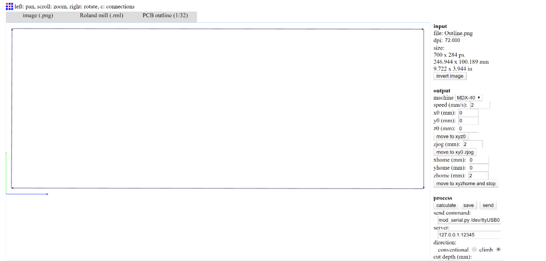
For the outline we made it in Adobe illustrator and then we followen almost the same steps as before.
1- Go to: www.fabmodules.org
2- Click on input format and choose (image.png)
3- Select the image of the outline, click open.
4- Click on output format and select (Roland mill (.rml)
5- Click on process and select (PCB outline (1/32)
6- In the output section, change the machine option into (MDX-40)
7- In our case we changed the tool diameter to: .5 and Z home: 2
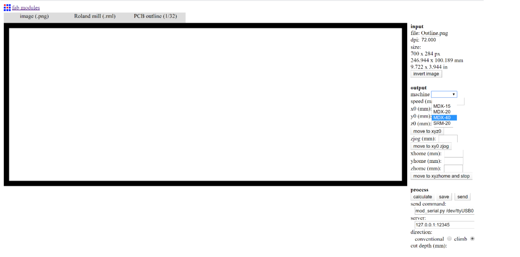
8- calculate and save:
16- Click on (save).
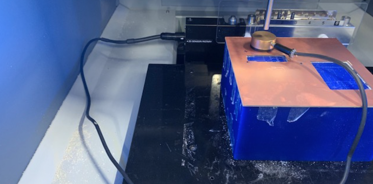
Go to the Milling machine in our case Roland MDX-50
1- Press on menu and set the x, y, and z axis.
2- Click on menu twice and choose (tool 6) and use the calibration tool to calibrate the z-axis.
3- Set the correct tool for the traces and select it by clicking menu twice and clicking the number of the tool.
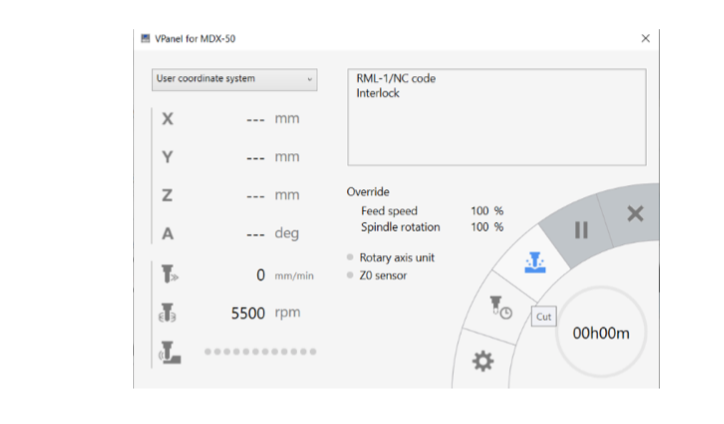
4- Open Vpanel and upload the file you want to trace and then click output, the machine should start working after this.
5- When done change the tool for the outline by clicking menu twice and clicking the number of the tool .
6- Open Vpanel and upload the file you want to cut and then click output, the machine should start working after this.
Individual Assigment
Download the PNG files for the traces and the board outline:
Traces (1000 dpi)
Outline Cutout (1000 dpi)
And follow the same proces we did before or follow the manual of your own machine or lab.
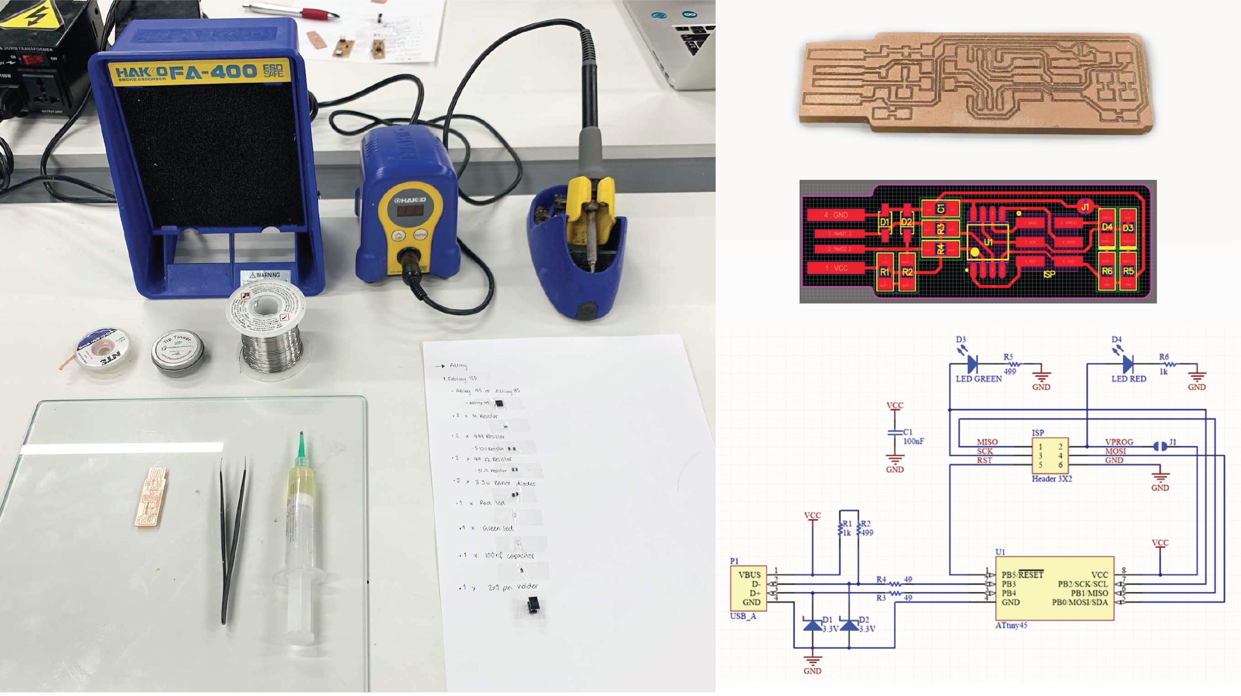
To assamebe the PCB you have to obtain the following components, in parentesis what I used or replaced:
- 1x ATtiny45 or ATtiny85 (1x ATtiny45)
- 2x 1kΩ resistors
- 2x 499Ω resistors (5100Ω resistors)
- 2x 49Ω resistors (51Ω resistors)
- 2x 3.3v zener diodes
- 1x red LED
- 1x green LED
- 1x 100nF capacitor
- 1x 2x3 pin header
Solder the parts to the PCB, using the schematic and board image below as a reference for component values and placement. Start with the most difficult parts (the ATtiny45) first, so you have the most access. Install the ISP header last, as it is large and can get in your way if you do it earlier.
A timelapse of the soldering process:
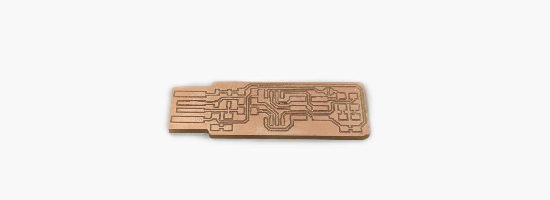
The results:
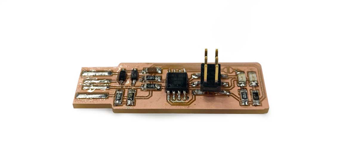
The challenges:
Before joining the lab, I have only done SMT (surface Mount Soldering) once before, but only as a try out. This was my first board and one of the challenges I faced was holding the small components in place as well as controllin the amount of solder I should use, during the soldering I had a few short circuits that actually thought me how to remove soldering. I was really glad with the results cuase it worked! and below ypu can see the picture with the green LED on.
Program the ATtiny45
The PCB that I am working on is called Fab TinyISP, it is a microcontroller that can be used to program other boards. However, it is still not programmed to do that, and what we need to do is to program it to be able to program other boards.
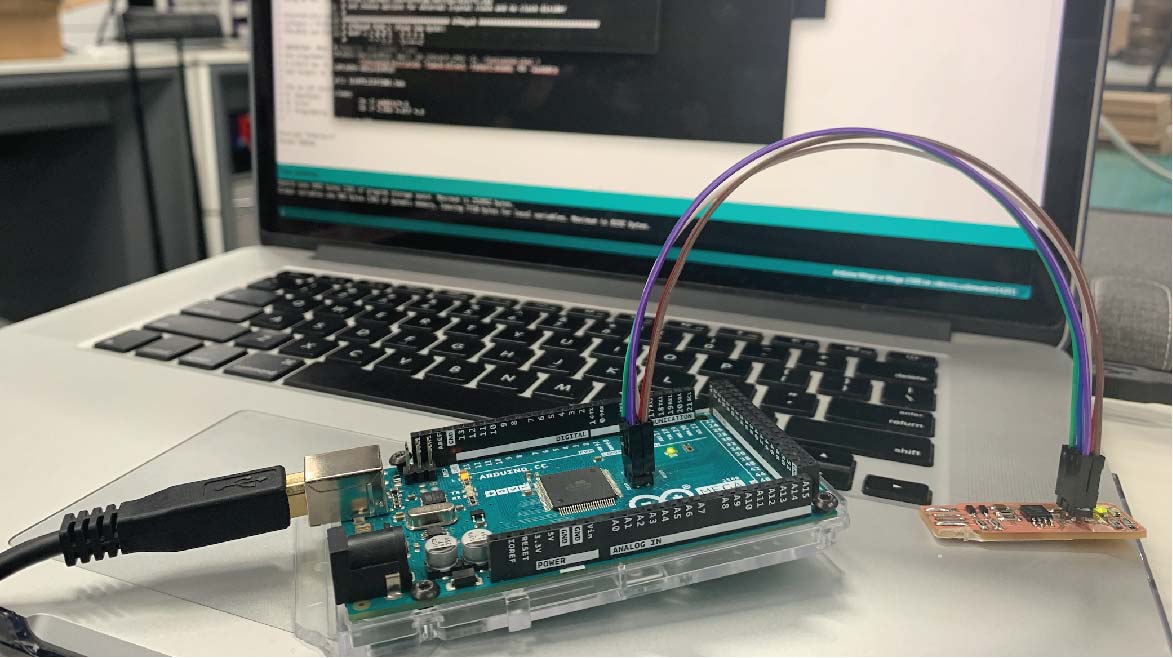
For that purpose we are going to use arduino as the tool that will help us program our Fab TinyISP.
To do that follow the following steps:
-Connect your arduino to your computer.
-From Arduino IDE go to File - Example - Arduino as ISP.
-Upload the code to your arduino, and by this your arduino now will act as a programmer.
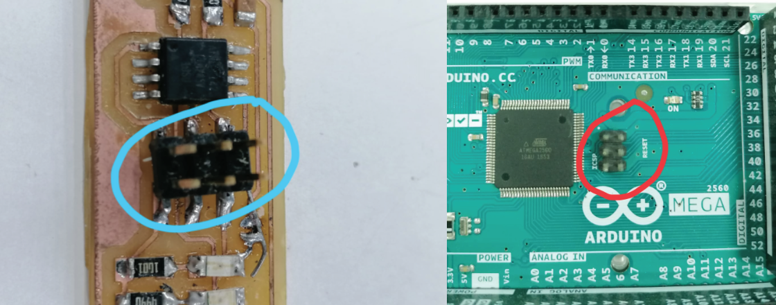
-Next when you are done with these steps, you will have to connect the programming pin of your Fab TinyISP to the programming pin of your arduino. The programming pins are the following:
MISO.
MOSI.
SCK.
Reset.
GND.
These pins are the 6 headers in your Fab tinyISP, and you can find the same 6 headers in any Arduino developing board, with the same pins orientation as your Fab TinyISP (See the picture).

The next steps are the challenging, programing your Fab TinyISP, is different when using different operating system. The easiest and the recommended operating system to use for programing your Fab TinyISP is Linux OS. However you can still use Mac and Window to do so but you will have to download specific software for that.
For mac -> Download and install
CrossPack
-Download the firmware source code and extract the zip file.
-Open your terminal program and cd into the source code directory.
-Connect the programmer to the ISP header on your board. Note that there are two different orientations in which you can connect the cable; it is imporatant that you get pins in the right place
-Run make.
-Edit the file called Makefile.TextEdit on OS X usually works, just make sure you save as plain text and not RTF (and make sure no ".txt" gets added to the filename).
-Near the top of the file, find the line that says:
PROGRAMMER ?= usbtiny
and change usbtiny to whatever programmer you're using.
-Plug the board into a USB port, It is also recommended to use a short USB extension cable or a USB 2.0 hub rather than plugging directly into the port.
-Run make flash.
Useful links