Mechanical Design, Machine Design
Week 17
Machines and Materials
Softwares
Files
Group Assignments
Actuate and automate your machine
Group Assigment
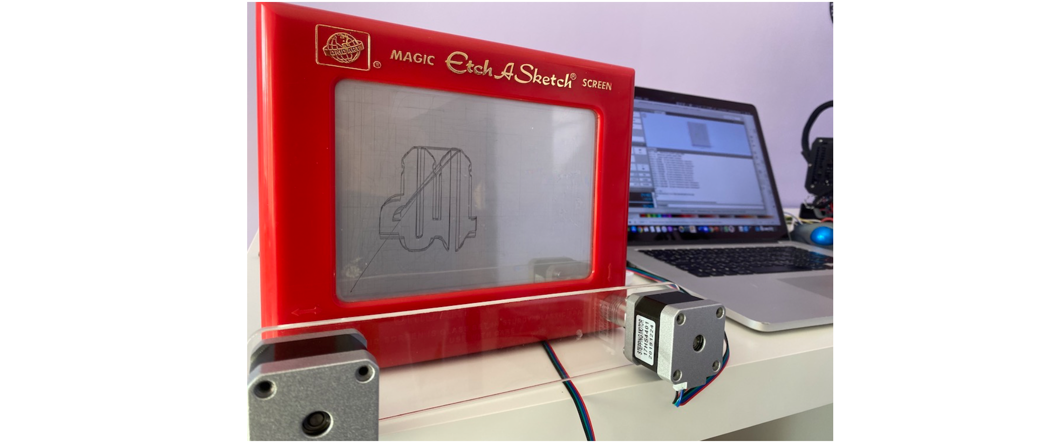
During this week we are going to explored machines and differen't kind of mechanical designs and actuation systems. The assignment is to design a machine that includes mechanism, actuation and automation. as a group we decided to go with an Etch-a-Sketch plotter and automate it.

An Etch A Sketch has a thick, flat gray screen in a red plastic frame. There are two white knobs on the front of the frame in the lower corners. Twisting the knobs moves a stylus that displaces aluminum powder on the back of the screen, leaving a solid line. The knobs create lineographic images. The left control moves the stylus horizontally, and the right one moves it vertically.
We Divided the work into 3 parts between 4 people in the group.
1- Mechanical actuation of the toy ( Achraf and Abdulrehman )
2- Electronics and motor drivers (Katya Diaz)
3- G code generation and programming the controller (Ahmad )

Part 1 - Mechanical system
There are multiple ways to connect the moors to the etch a sketch knobs. We considered using direct gear connecs, belts, shaft to shaft couplers. The first option would required several iterations to get the gear alignments right. So Achraf designed a belt system where the toy and the motors fit in a frame and connected by belts and geared pulleys.
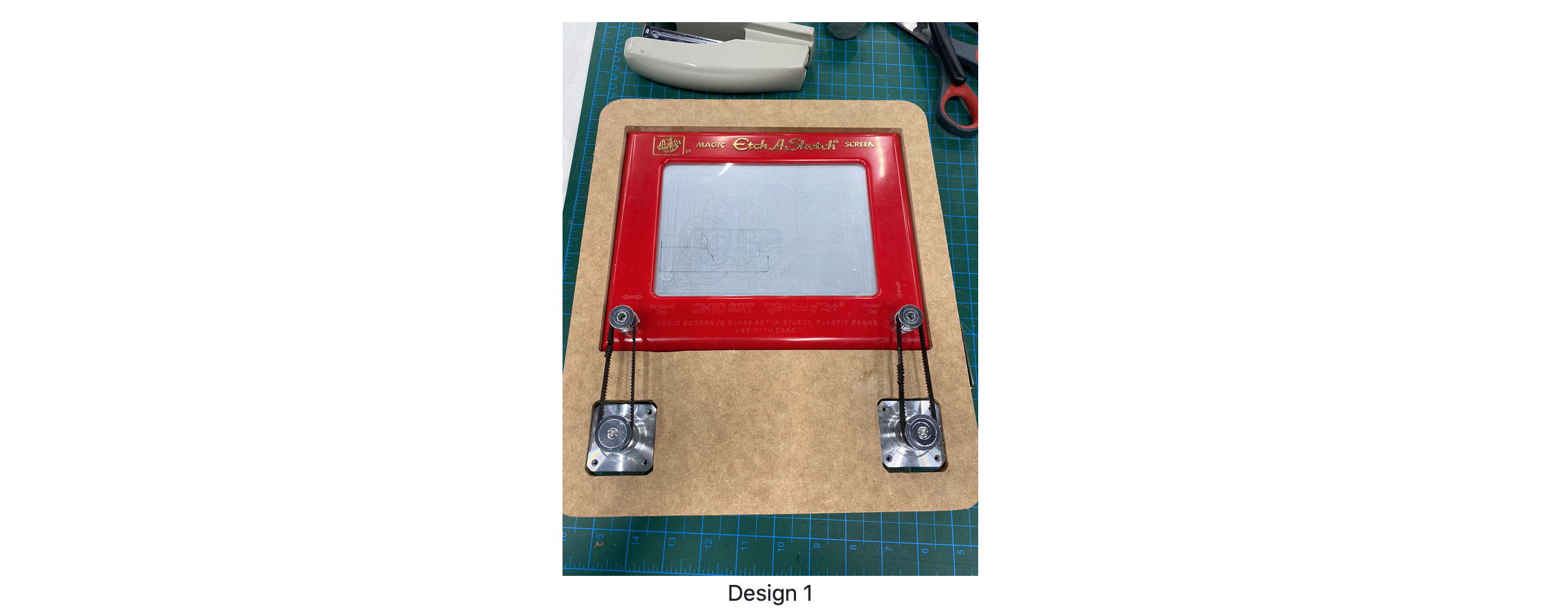
The belt tension was not enough so we had to alter the dessign, we tried a new system where a single piece of will hold the motos and will fit vertically over.
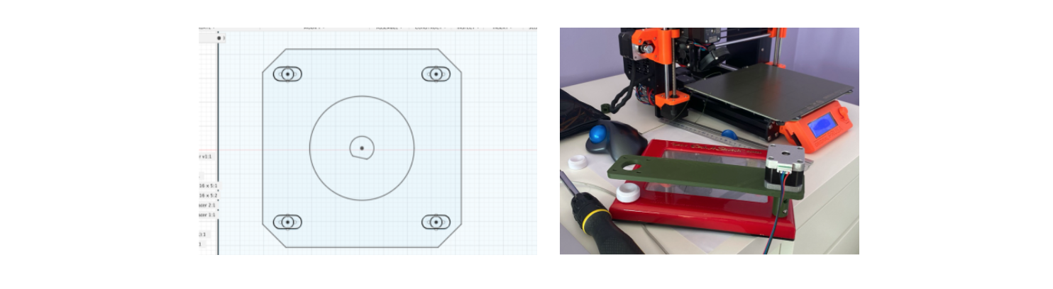
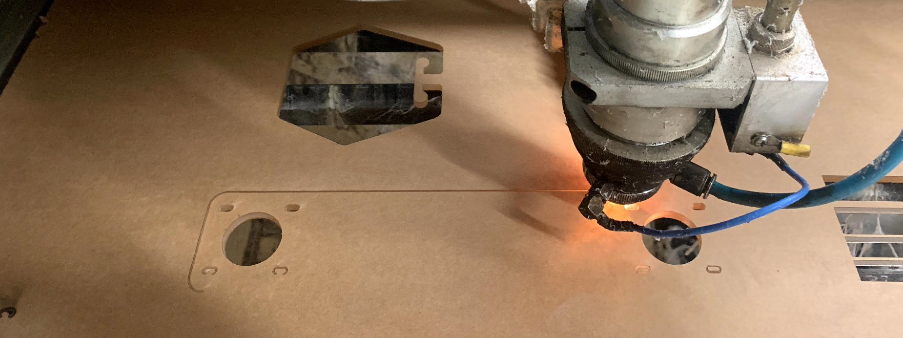
This worked ok as a prototype but we needed better couplers and a more rigid holder. We decided to cut the final piece in acrylic.
Part 2 - Power and Electronics
This machine uses two stepper motors to control the drawing head. Each motor will move one axis. To control the motors, we used two Nema17 stepper motors and an Easy Driver to control the motors.
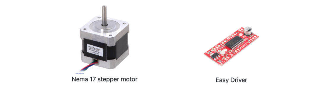
The Easy Driver houses a A3967 IC which is a complete microstepping motor driver with builtin translator. It is designed to operate bipolar stepper motors in full-, half-, quarter-, and eighth-step modes, with output drive capability of 30 V and ±750 mA.

With it's wide range of input volate and the easy to connect it to the Arduino, this driver was the ideal candidate for out project.
However, enabling the microstepping (by connecting the MS1 and MS2 pins) would be an overkill for this kind of machine. Each motor was connected to a separate easy driver. The motors came with jst sockets that made it easy to identify coil A and coil B on each motor.

The other pins that were connected to the drivers are power in (v and gnd) and the 3 pins in the bottom right corner (GND, Step, Direction). The step and direction pins are how the arduino can control the motor. with every signal recieved the motor moves a step in the direction indicated by the step pin.
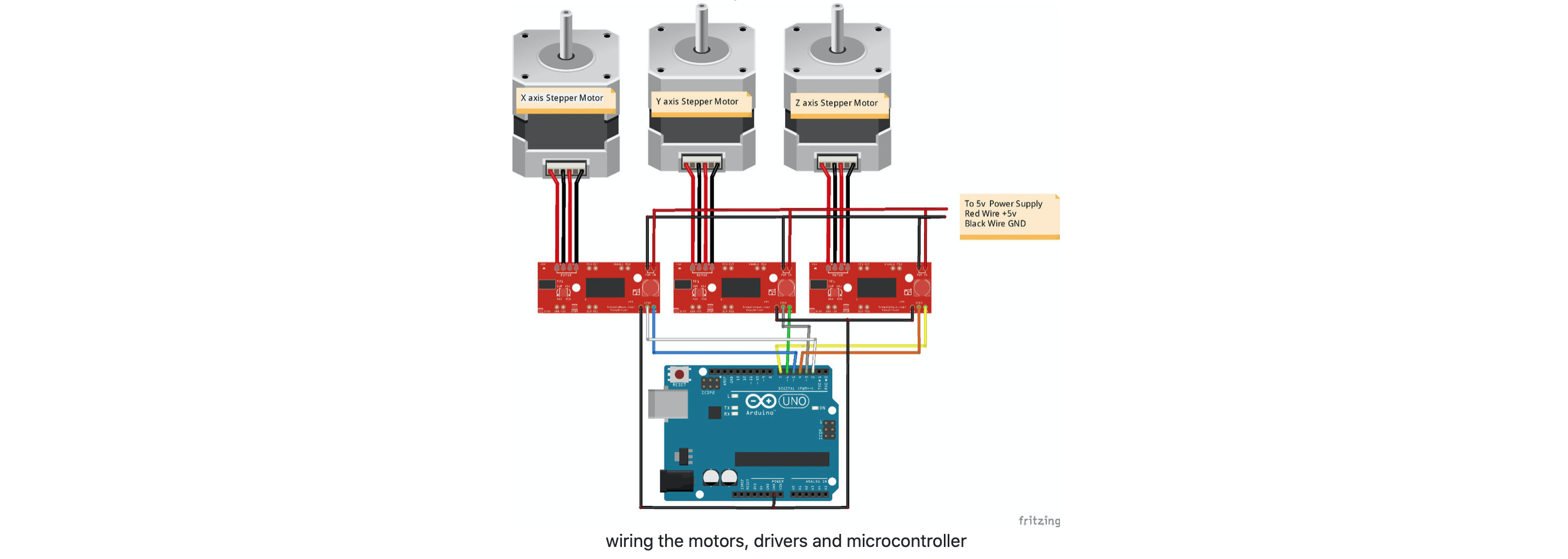
It's important to note here that the picture above shows 3 motors, but we only used the X and Y motors in our project as there was no Z axis to control. It's also important to connect the step and direction pins to the correct pins on the arduino as they will later be used by the grbl controller (see part 3). the pins should be connected as follows:
D2, D3, D4 = X, Y, Z step
D5, D6, D7 = X, Y, Z direction
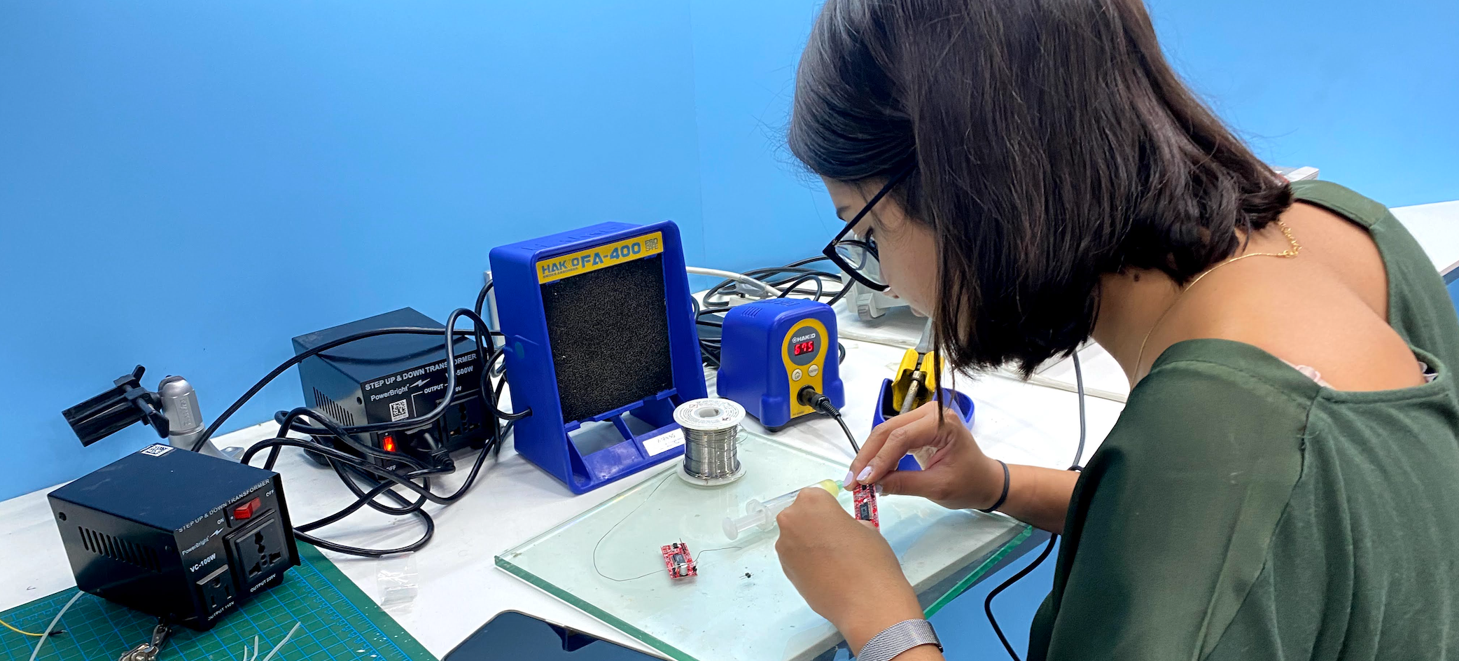
I continued by soldering the pins on the easy driver board
Finally, to power the motors, we used a 12v DC power outlet that powered both drivers in parallel.
Part 3 - Software
This is the part where the automation comes in. We used GRBL to control our machine. GRBL is an open-source g-code parser and CNC-milling controller. Its runs on Arduino or any other board supporting Atmega 328.
first we download grbl library from https://github.com/grbl/grbl.
Then we install grbl library to Arduino IDE:
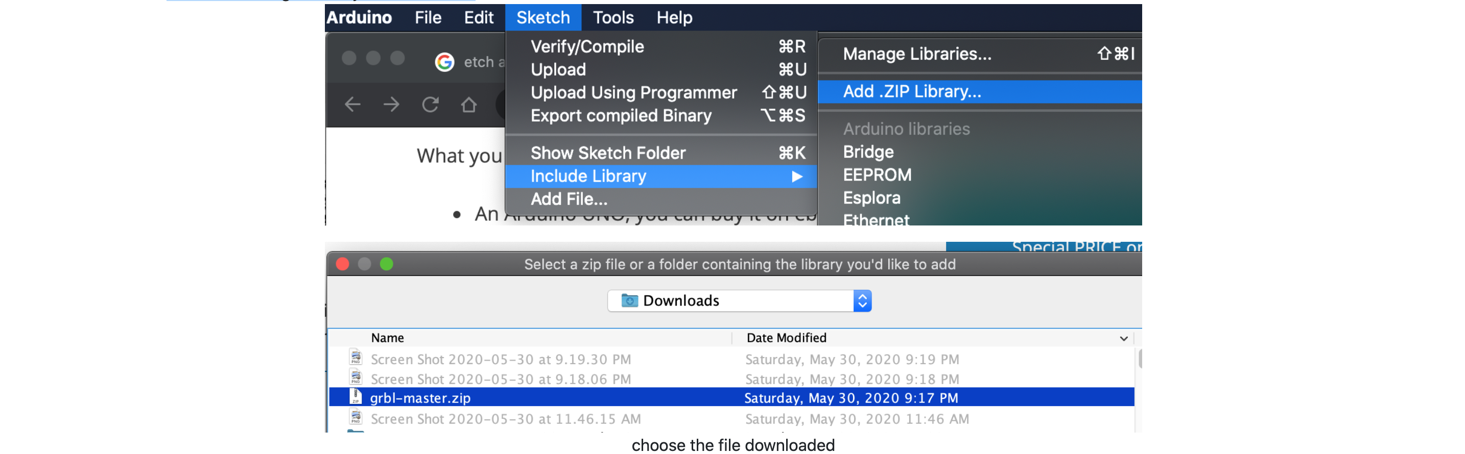
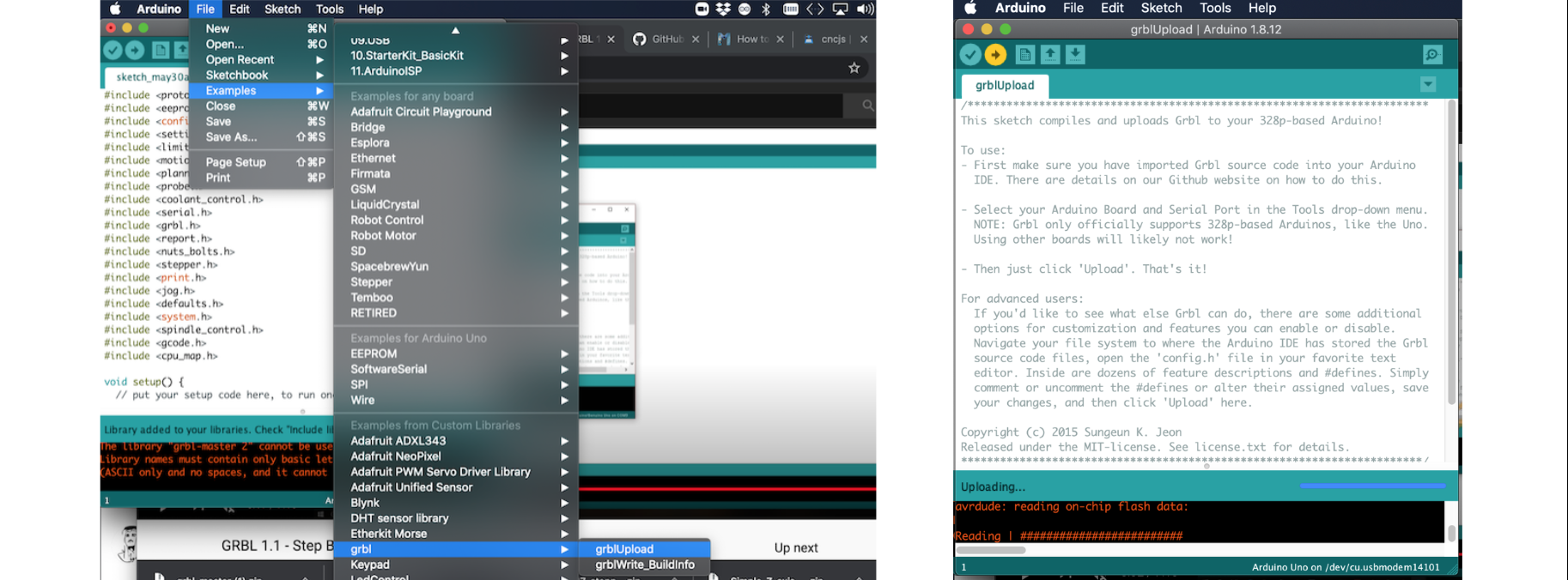
The grble code is included as an example in the library. we opened the example and uploaded the code on the arduino.
Now that the arduino is ready to receive our gcode and control the machine, we need to send the gcode to the arduino/grbl.
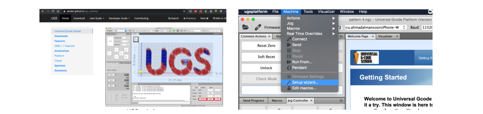
This is done via serial connection and we chose to use UGS (universal gcode sender). There other options available but this one seemed easy to use and suitable for our assignment.
by going to https://winder.github.io/ugs_website/download/ we downloaded UGS platform. There are 2 versions of UGS which have the same function. We decided to use UGS Platform.
After downloading UGS, we had to connect it to our machine (arduino). The easiest way to do this is to use the setup wizard.
The setup wizard takes care of connecting the arduino to the laptop and also helps calibrating the motors. It's important to specify the platform and the baud rate of the arduino. The next step is very cruicial and it'll help the machine "obey" the instruction as intended. We need to calibrate the machine steps to specify the steps for every mm moved. Thankfully UGS has an easy way to do this:
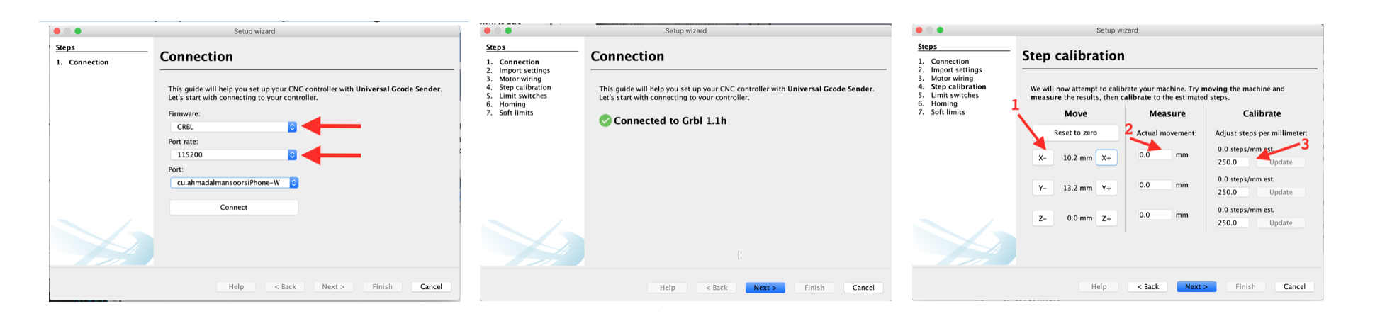
To explain this step: click on each axis to move the machine a certain distance. Measure the distance physically moved by the machine. This should calculate a new steps/millimeter number. type this number and update the machine.
Once this is done, the UGS is now ready to take your G-code. In previous projects, many machines we used had their own g-code generators. We also explored tool paths generated by CAD software like Fusion 360. However, when it comes to 2D drawins, I couldn't find many options. The most popular way (although not ideal) was using Inkscape. Inkscape has an extension that generates gcodes from 2D drawings.
Here is an example on the drawing converted to Gcode:
1- open drawing/pic in Inkscape
2- trace bitmap (Path > Trace Bitmap)
3- create offset (Path > Dyamic offset)
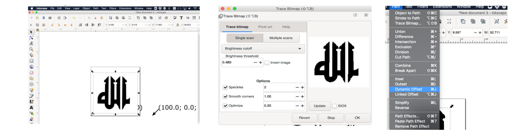
4- Delete original photo and keep the offset
5- Open Gcode Extension
6- set name and directory of Gcode
7- go to Path to Code tab and click Apply
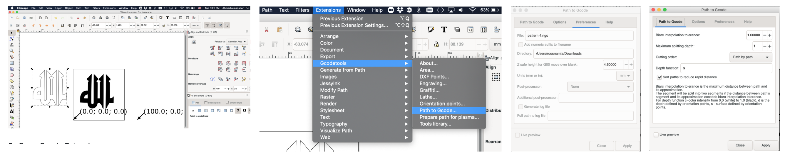
The software will then calculate a G code and send it to the specified directory under the specified name. Note that the tool size was not specified. The software has a default tool that it uses. If you have a different tool and would like to specify it, you can do this under the Gcode extension.
Next we can open the gCode in UGS:
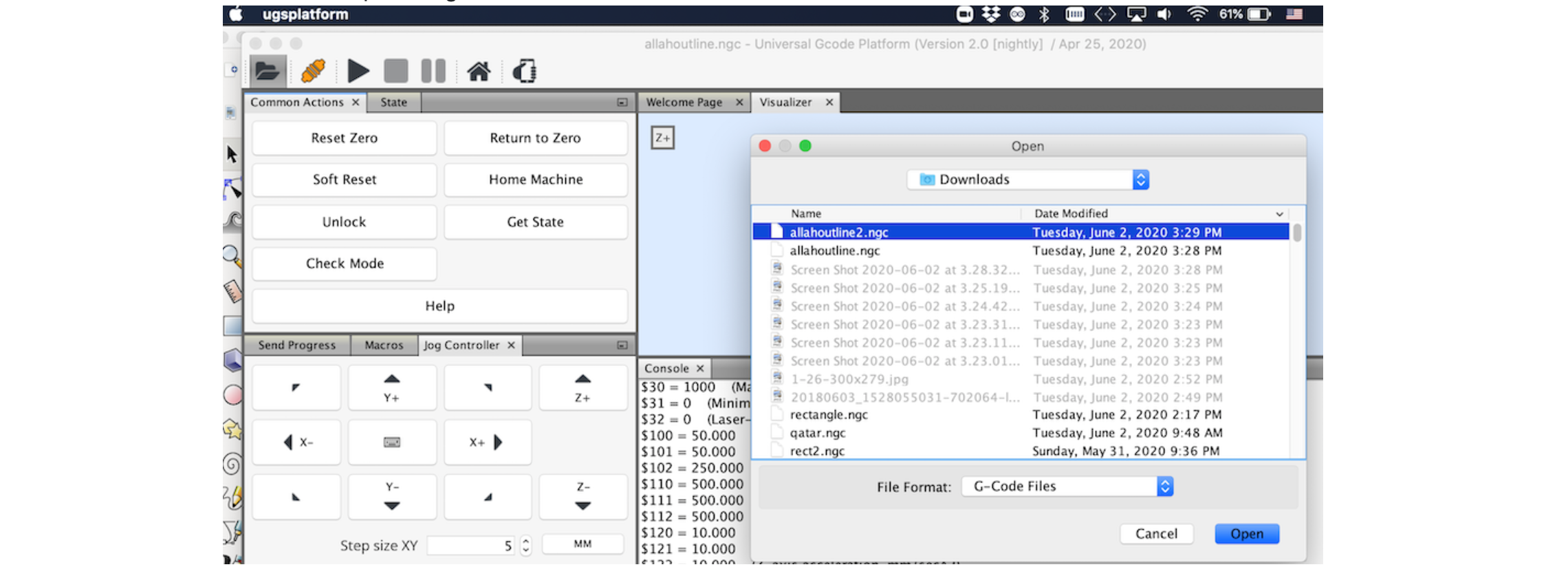
UGS platform has a visualizer that helps visualize the tool and the path. By manually homing the machine and then clicking on Reset Zero in UGS we retered the machine to it's datum.
Then finally we can send the code the arduino/grbl and have the motors follow the code.
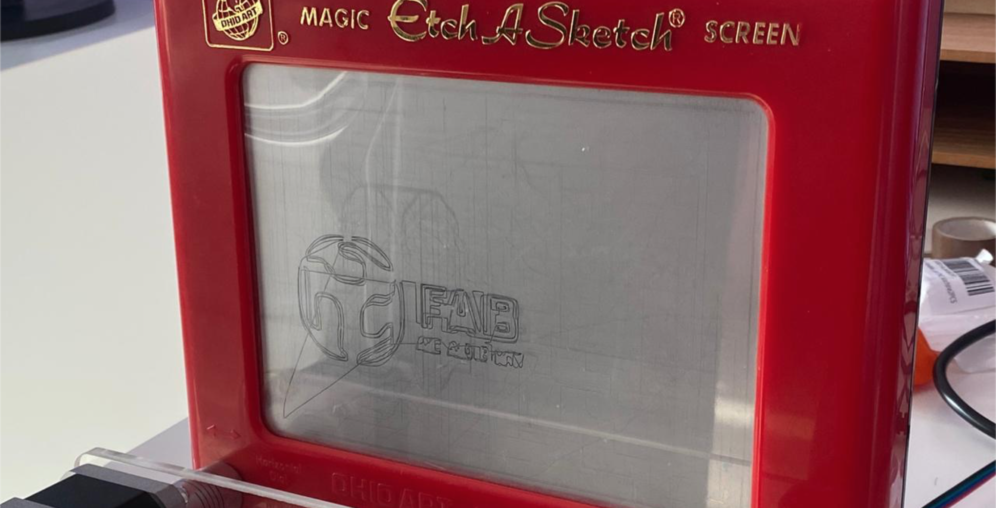
Here is another sketch made by our machine:
Making any kind of machine, requires effort and planning on advance. In our case we are planing to improve our machine and fix its stetics and calibration to obtain better results. Etch a sketch is a toy and it has a some hysteresis. This can be felt even when controlling the machine by hand.