Embedded Networking and Communications
Week 14
Machines and Materials
Softwares
Group Assignemt
During this week we are going to design, build, and connect wired or wireless node(s) with network or bus addresses since we had limited access to the lab my project was developed with and arduino board to demonstrate workflows used in network design and to implement and interpret networking protocols and/or communication protocols.
Individual Assigment
Design, build, and connect wired or wireless node(s) with network or bus addresses
- Documented your project.
- Documented what you have learned from implementing networking and/or communication protocols
- Explained the programming process/es you used.
- Outlined problems and how you fixed them
- Included design files (or linked to where they are located if you are using a board you have designed and fabricated earlier) and original code.
Components
- NRF24L01
- DHT11 Sensor
- LCD Display
- 10K ohm potentiometer
- Resistor
- Arduino Uno
- Wires
The key componet for this project was the NRF24L01 Transceiver Module

The nRF24L01 is widely used un applications that require wireless control. The nRF24L01 is a transceivers module which means that each module can transmit and receive data.
Specifications
(https://components101.com/wireless/nrf24l01-pinout-features-datasheet)
- 2.4GHz RF transceiver Module
-Operating Voltage: 3.3V
-Nominal current: 50mA
-Range : 50 – 200 feet
-Operating current: 250mA (maximum)
-Communication Protocol: SPI
-Baud Rate: 250 kbps - 2 Mbps.
-Channel Range: 125
-Maximum Pipelines/node : 6
-Low cost wireless solution
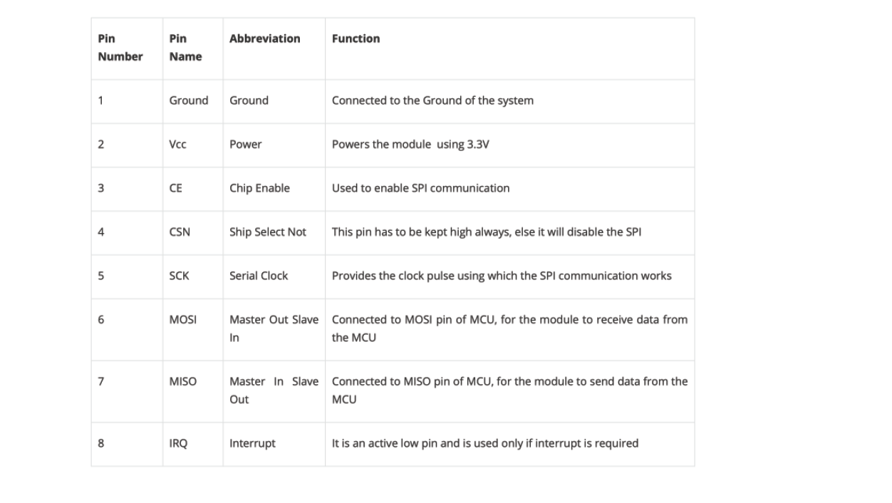
nRF24L01 Pin Configuration

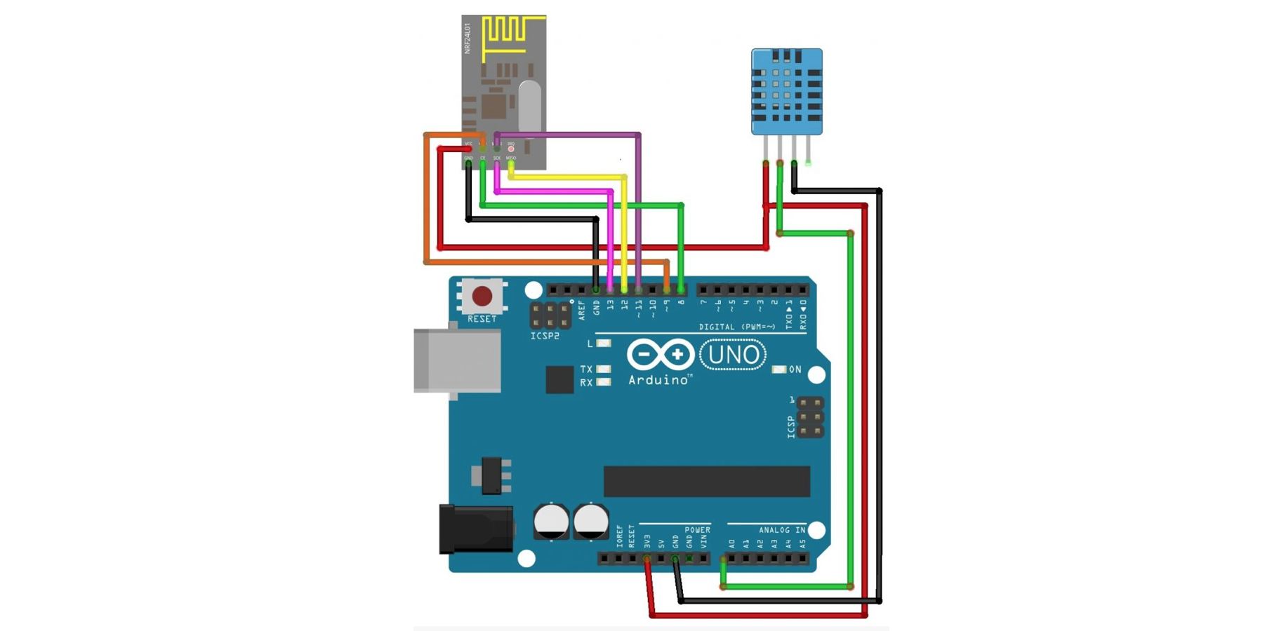
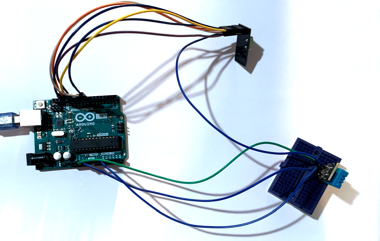
Wireless Temperature Monitor:
For this assignment we will develop a Wireless Temperature Monitor, first we start by following this diagram for the first arduino board. This will work as the transmitter.
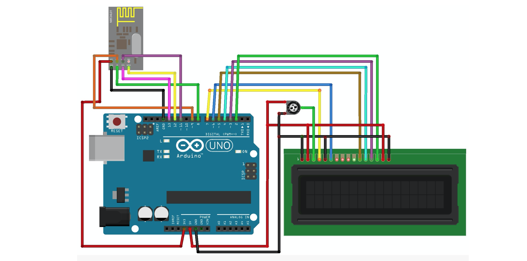
The second board will work as the receiver:
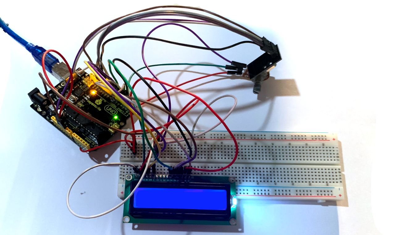
Now we will continue with the code.
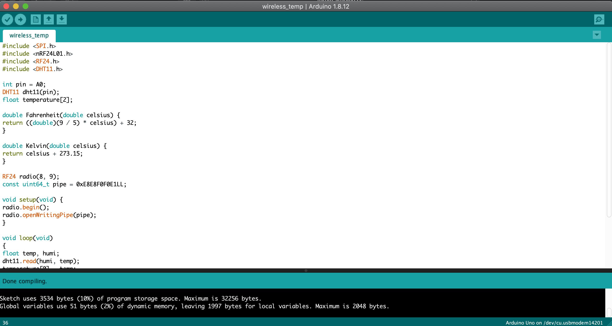
At the the first try I encounter some problems, for it to work double check that all the libraries included and if one is not working try downloading it again
Here is the code for the trasmitter:
For the second arduino, the receiver you can use the following code
Once again, I had some troubles with the screen, since it has a lot of conections is really easy to misconect one. After double checking the conection rotate the knob of the potentiometer to adjust the brightness and make it visible.
For the final test I powered one arduino with another laptop and checked it was working, here are the final results
