Output devices
Week 11
Machines and Materials
Softwares
Group Assignemt
During this week we are going to be using sensors to measure something: add a sensor to a microcontroller board that you have designed and program it to do something, in my case I have been working from home due to covid so I will be using an arduino board to test my output device.
Individual Assigment
Add an output device to a microcontroller board you've designed and program it to do something
- Documented what you learned from interfacing output device(s) to microcontroller and controlling the device(s)
- Described your design and fabrication process or linked to previous examples.
- Explained the programming process/es you used
- Outlined problems and how you fixed them
- Included original design files and code
- Included a ‘hero shot/video’ of your board
Components
- Ultrasonic Sensor
- LCD Display
- 10K ohm potentiometer
- Resistor
- Arduino Uno
- Wires
I started by testing the LCD screen fisrt, in the following diagram are the pins on the LCD I’m using.

Arduino conections:
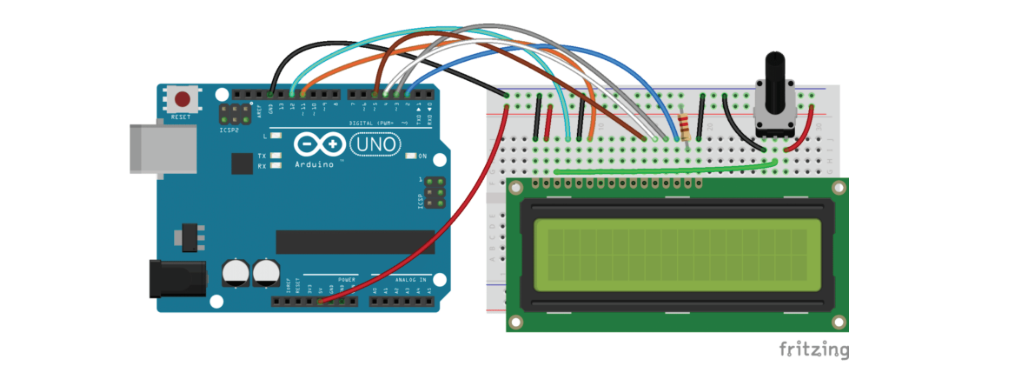
Preliminary testing:
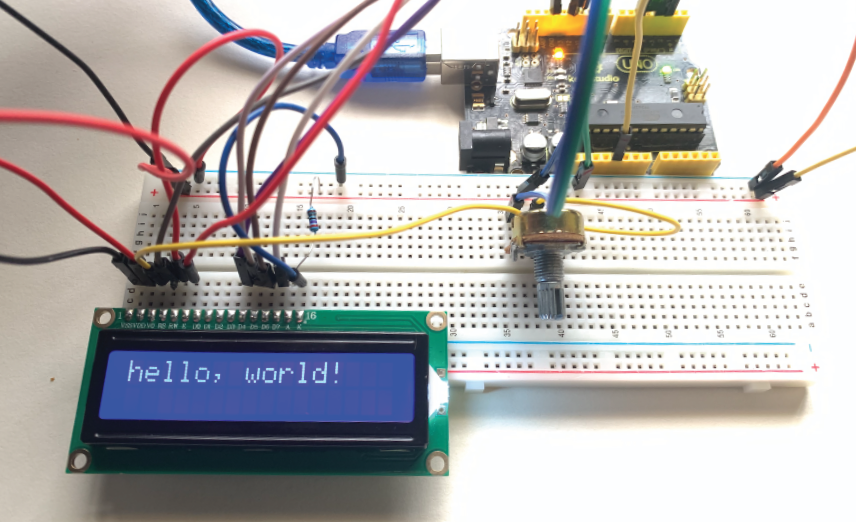
I started by testing a simple Liquid Crystal LCD screen, the results where succesful just after a rotated the pontentiometer knob. The pontentiometer knob controls the brightness of the sceen and before adjusting it, the text was not visible.
Also, I had to double check the conections since its really easy to pin it in the mistaken hole and it will not work.
Ultrasonic Sensor
Ultrasonic range finders measure distance by emitting a pulse of ultrasonic sound that travels through the air until it hits an object. When that pulse of sound hits an object, it’s reflected off the object and travels back to the ultrasonic range finder. The ultrasonic range finder measures how long it takes the sound pulse to travel in its round trip journey from the sensor and back. It then sends a signal to the Arduino with information about how long it took for the sonic pulse to travel.
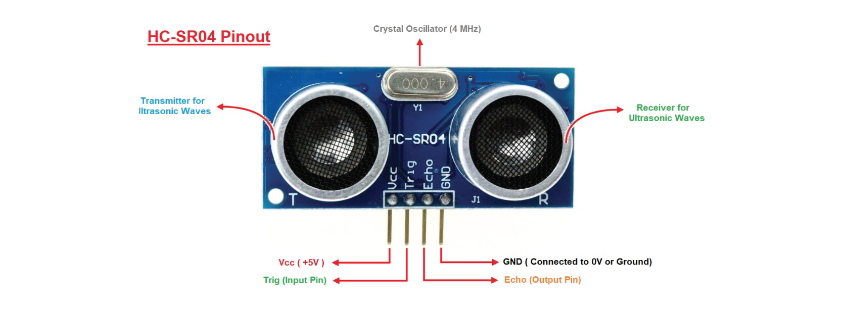
The HC-SR04 ultrasonic range finder has four pins:
Vcc – supplies the power to generate the ultrasonic pulses
GND – connected to ground
Trig – where the Arduino sends the signal to start the ultrasonic pulse
Echo – where the ultrasonic range finder sends the information about the duration of the trip taken by the ultrasonic pulse to the Arduino
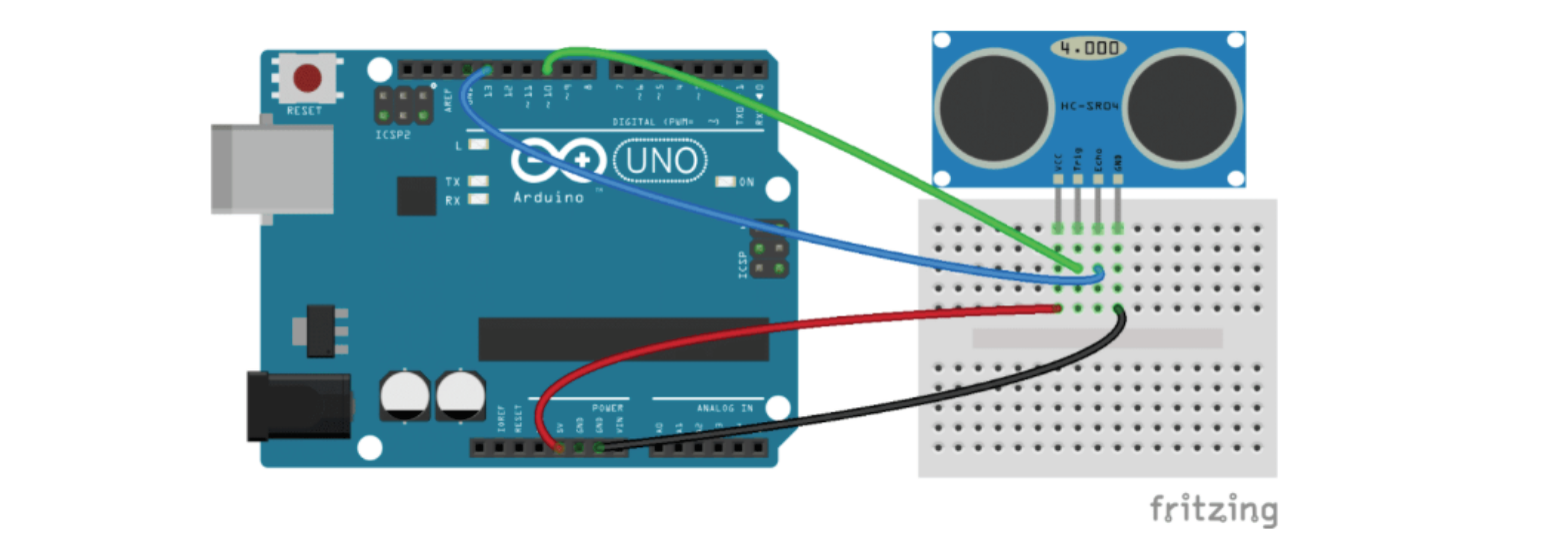
After researching about the Ultrasonic sensor I proceeded with the conections.
Ultrasonic sensor diagram:
(just add it to the previos connection made)
Code:
Final results: