Week 7
Computer Numeric Control (CNC) was used to control a milling machine. In ourlab we use ShopBot machine. This week we explored cutting wood, primarily MDF, to produce "something big".
I designed a chair using Fusion 360 and then exported the files to the machine.
Group Assignment
Like other manufacturing machines, CNC cutters have to follow certain design rules. As will be shown in later sections, internal angles can't be sharp due to cutting tool diameter. There are other ways to go around this limitation. Dogbone cuts, for example, can be added to internal angles to make way for the drill bit path.due to limited lab access, this assignment was partially skipped.

Individual Assignment
ٍRocking Chair
Fusion 360 was used to design this chair. Setting the material thickness in Design Parameters is important not only to give a good representation of the model, but also to accurately design cuts in the model.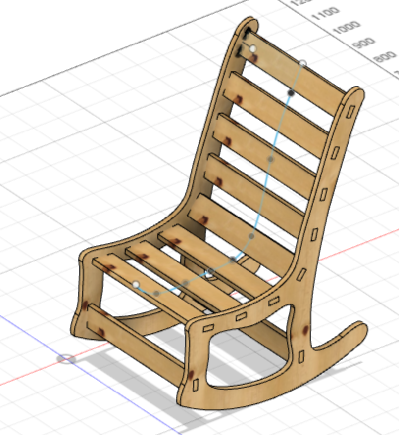
I prefer designing in 3D model and later flattening all bodies and converting the 3D model into a 2D .dxf file. The steps below will show the steps of modeling and printing.
 ---->
---->  --->
--->
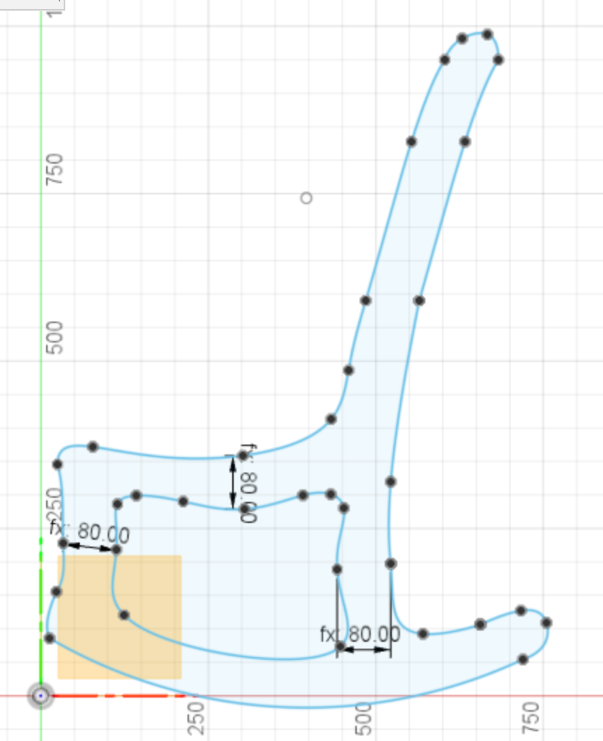
The sides of the chair were designed first using a spline tool. A curve was added to the bottom for the "rocking" function of the chair. The dimensions of the chair were estimated and roughly based on other chairs around me.
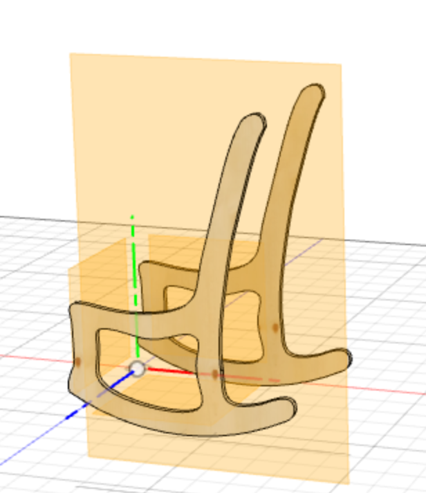
After extruding the side to the wood thickness (used-defined parameter), anothe copy of the of the side was made to construct the other side.
Finally, the cross pieces were simply an extruded rectangle that connected the two sides. Using Pattern on Path tool, I was able to create multiple pieces in the desired way.
Note: Pattern on Path may produce pieces in angles that are not desired. To Position the replicated pieces correctly, Move tool was used At this point, the pieced of the chair only intersect visually. No cuts were made yet.
To create these cuts, Combine tool was used with the sides as target bodies and the connecting pieces as tool bodies. This creates cuts that were exactly the size of the pieced that will go through them.
The next step is cruicial. To lay the the pieces flat Align tool was used for every individual piece. It's important to lay them on the XY plane and not on the default XZ plane. This will come in handy when creating dogbone cuts.
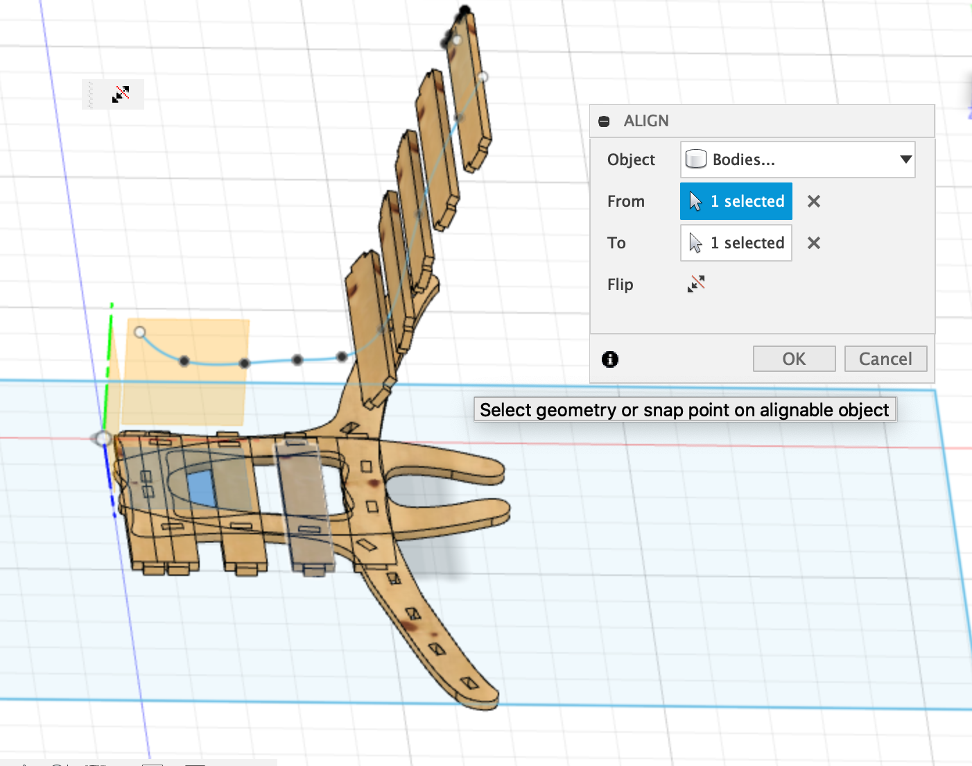 ---->
----> 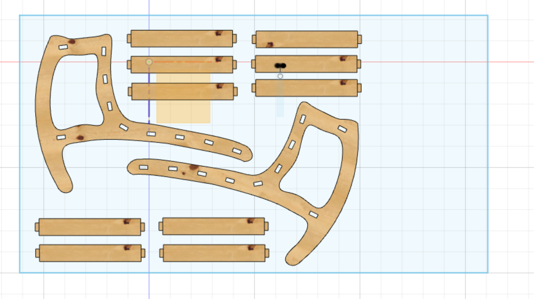
Once all pieced are layed flat, the can be movied around so they're not overlapping.
Dogbone cuts
Creating dogbone cuts can be done manually. There are other cut style that can be used too. T-bone cuts are also popular. However, I found a useful add-in in Fusion 360 that automates this process. By simply selecting the bodies and the tool diameter, the software will recognize all internal angles and create a circular cut around the angle.It's important here to point out that this will only work if the pieces are on the XY plane with the Z up.

Finally, the outline of these pieces was projected on the new sketch. This step is to create a .dxf file which can only be created from sketches. Using Project tool and selecting the bodies, the lines were projected on the new sketch. This new sketch was saved as .dxf file and was ready to be sent to the CNC machine software.
TO DOWNLOAD THE .DXF FILE CLICK HERE
CNC cutting
The machine used in our lab is ShopBot PRSalpha. The software that was used to create the tool path is called Vcarve Pro.
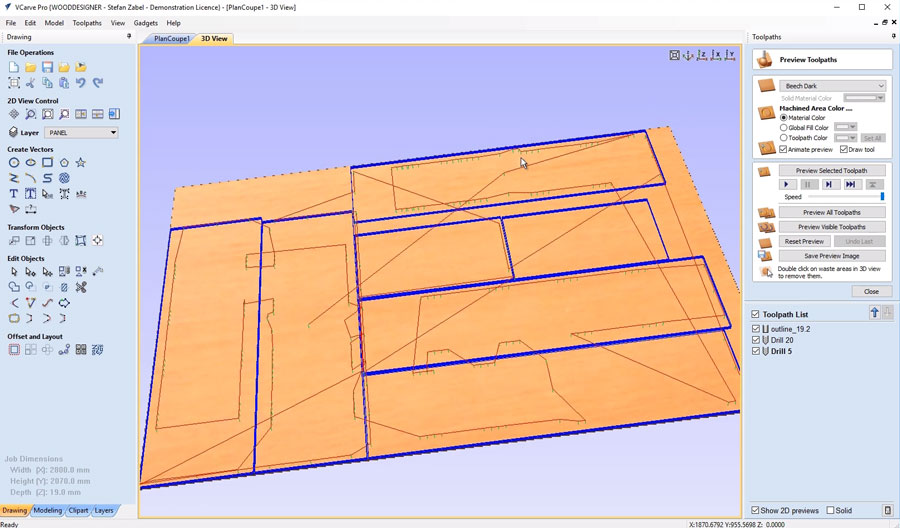
First the .dxf file was imported in Vcarve Pro to generate the tool path. A 6mm tool was used with 20 tool passes for every pieced. This might have been an over kill and something like 10 or 12 passes would've been sufficient.
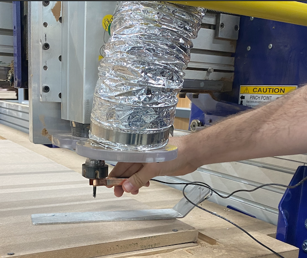
A 1.2m x 2.4m piece of MDF was put on the cut bed and the machine was started.
Below is a photo of the chair after assembly.
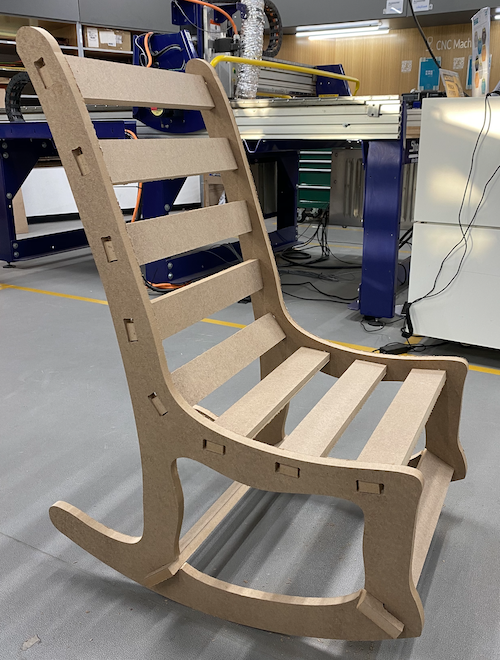
Lessons Learned
It's clearly evident in the photo above that the cut holes were too big for the pieces to fit in them. While the holes were adjusted on the 3D model to produce a tighter fit, this did not translate well on the machine.
My main conclusion on why ths happened is that the location of the cut was set incorrectly in Vcarve Pro. The cut tollerances were not accounted for, resulting in holes that are too big and pieces that are too small.