Week 6
Electronics programming week is all about making a microcontroller board and programming it. This tasks combine some of the skills acquired in previous weeks such as computer-controlled cutting and electronics production.
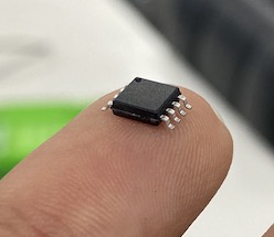
Attiny45 microcontroller chip was used to develop the programmable controller board. To program this board, the in-circuit programmer developed in week 4 will be used.
Group Assignment
Individual Assignment
Hello World!
The drawing of my board is based on the board below.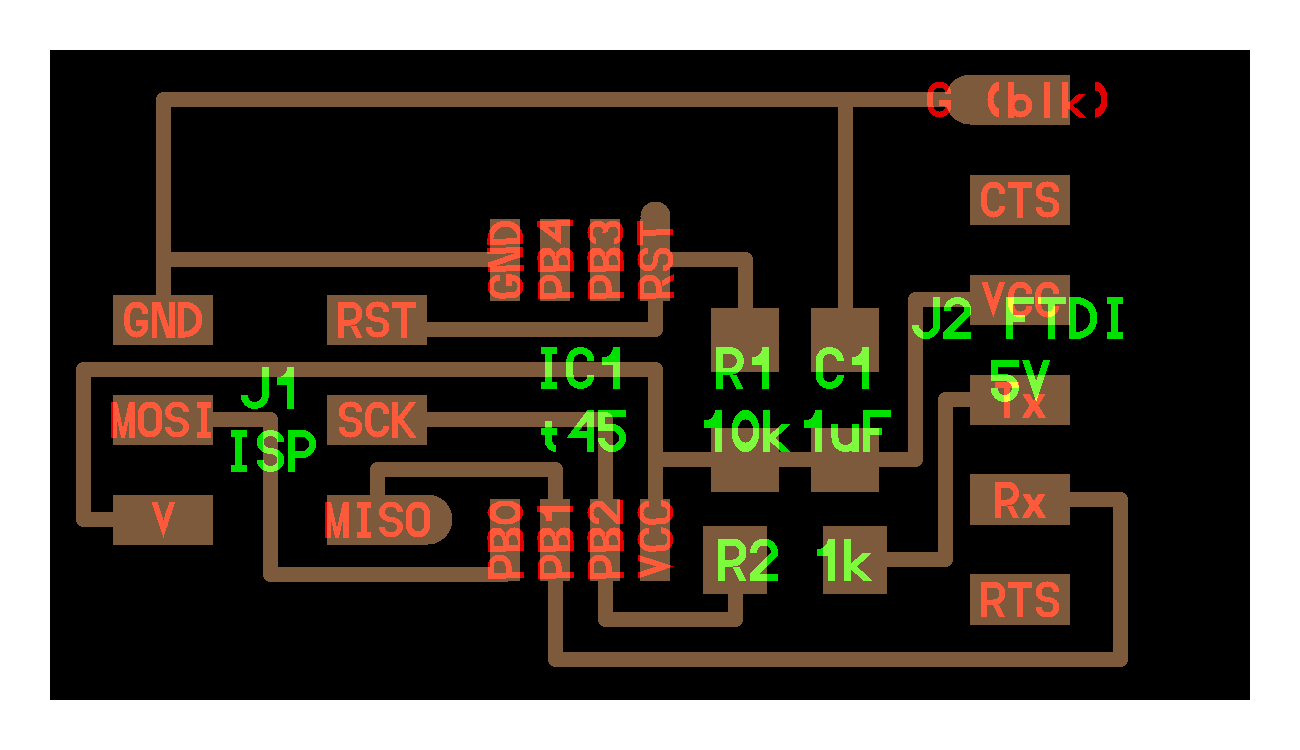
In addition to the board above, a push button swtich and an LED was added. These components require pull-down resistor and current limiting resistor, respectivly.
Below is a table with the component list that was used in my board.
| Component | Size | Qty |
|---|---|---|
| ATTINY45-20S | - | 1 |
| Switch | SPST_TACT-EVQQ2 | - |
| Resistor | 10K ohm | 1 |
| Resistor | 1K Ohm | 1 |
| Resistor | 240 Ohm | 1 |
| Resistor | 100 Ohm | 1 |
| Capacitor | 1uF | 1 |
| 6 pin male header | FTDI-SMD-HEADER | 1 |
| LED | LEDFAB1206 | 1 |
| AVRISPSMD Socket | 2x3 | 1 |
Moving to the board design, the Autodesk Eagle was used to draw the board and schematics. Eaglle was relatively easy to learn. One of the features that was of great help is Libraries. Importing libraries made it easier to search and add parts to the board. The components used on the board had to be SMD parts with footprint that matches the available components in our lab.
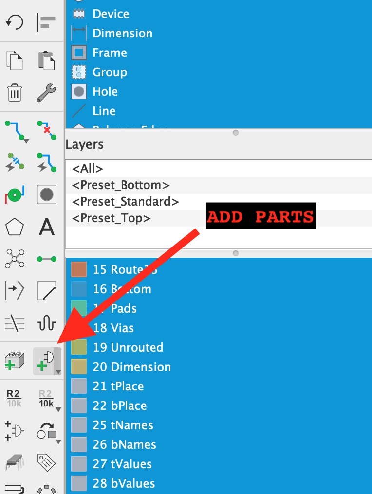
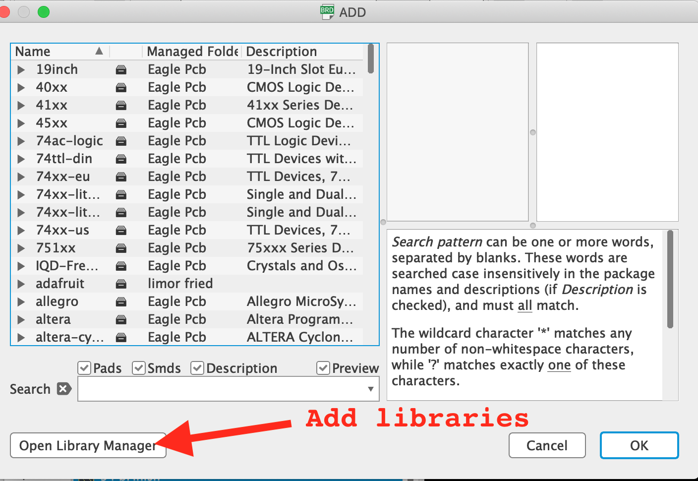
The parts on my board was added from Fabacademany Eagle Library. It can be downloaded from here
After adding the parts listed above, the were connected using the following schematics. I thought it was easier to draw lines and then naming them to connect them.

Swtiching to the board view, all components are visible as they will appear on the printed board. However, the connections have to be routed.
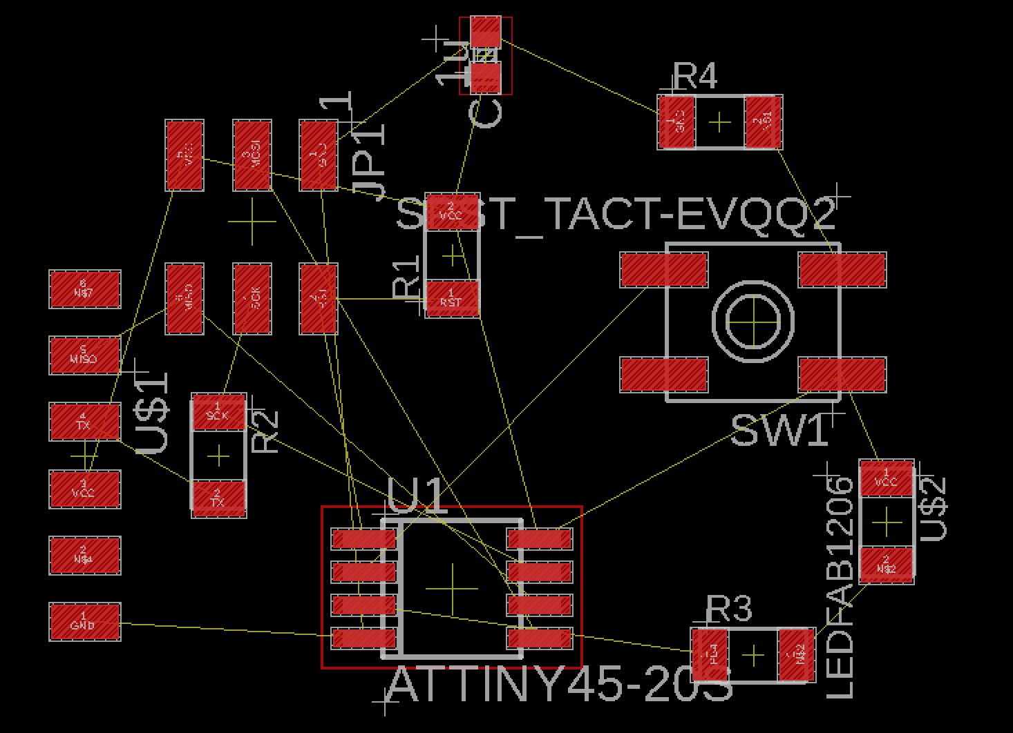
My board will be milled on a one-sided board and for this reason the connections can only be routed on one side. This makes is more difficult to connect parts without crossing other lines. Component layout is essential here. Placing the components in the correct configuration will make it a lot easier to route the traces.
It's worth mentioning here that Eagle has auto routing feature that outputs different configuration for the traces.
After tedious effort to place the components in a proper way, the folowing board was produced.

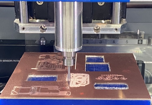
The connections for this board were exported as .png files and added to FabModules to create the tool path for the Roland MDX-50.

The components were then soldered on the board according to the board schematics.
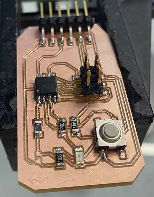
The next step is to flash the board with the ISP created before and then program it with the desired program.