Week 4
This has been the most challenging week in Fabacademy so far. We started talking about electronics production. Just like the previous week, this week's assignment was divided into two parts, an group assignment and an individual assignment.
Group Assignment
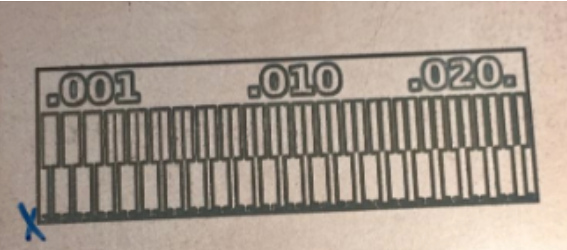
The group assignment was to characterize the design rules for PCB production pricess.The method used to produce PCBs was board milling. Using Roland MDX-50 milling machine, we were able to mill circuit boards. The assignment was to discover the machine and test the tolerances of the thin traces in the machine.
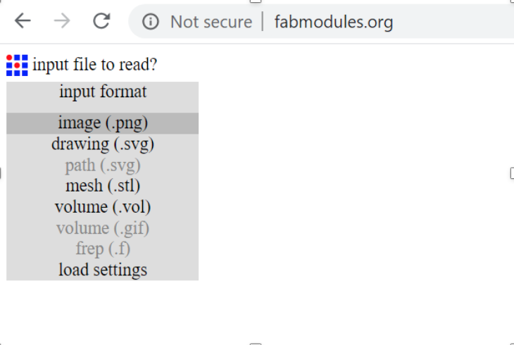
For our machine (Roland MDX-50) the following settings were set on FabModules.

These settings generated a tool path for the machine. The file was sent to the Roland software (VPanel) wherethe home point was calibrated and then started the milling process.

The final print turned out as intended with the conrrect cut dept for the traces and the outline.
Individual Assignment
In-Circuit Programmer
This part of the assignment was to make an in-circuit programmer using the PCB milling machine and then soldering all the parts on it. After soldering, the board can be programmed.The board we used is called FabTinyISP for which which the wiring diagram is shwon below.
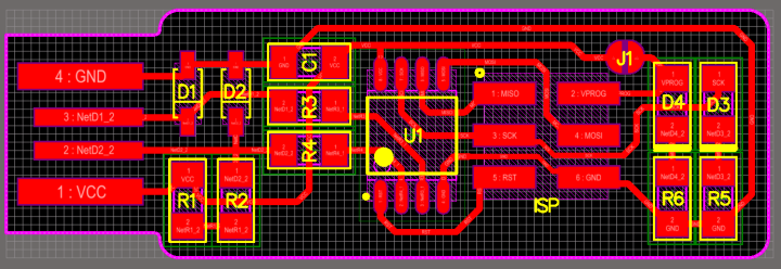
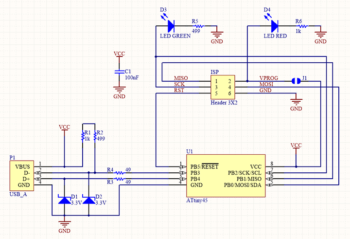
The Board drawing was then sent to the milling machine to create the traces and cut the board.

The components were then soldered to the PCB as per the schematics shown above.
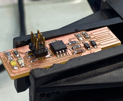
The board was then tested by connecting it to an Arduino Mega. This is to ensure that the ....

program the board....