Week 3
The third week of Fabacademy was about computer-controlled cutting. We explored Vinyl cutting and Laser cutting.
The assignment was divided into two parts:
Group Assignment
This part was to characterize your lasercutter's focus, power, speed, rate, kerf, and joint clearance as a group.The laser cutter in our lab is programmed by a software called LaserCut. LaserCut only accepts .DXF files and transforms into code that's read by the machine controller.
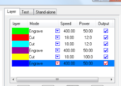
The softwares allows the user to assign lines to different layers. The layers are a way to order the cutting process as well as assigning different powers and speed to engrave or cut the lines in each later.
The power and speed are material dependant. This means every material will have different setting for the desired output (cutting or engraving). We used cardboard and the cutting settings were Speed:20 Power:100. Whereas for engraving it was set on Speed:100 Power:10 .
Individual Assignment
Part 1: Vinyl Cutter
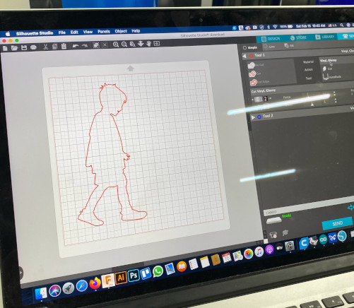
Vinyl cutting was used to make a personalized laptop sticker. The cutter in our lab is called silhouette cameo and uses a software called silhouette to control the machine. Just as in LaserCut (see above), this software accepts .DXF files. The Software can also be used to draw, scale and trace images.
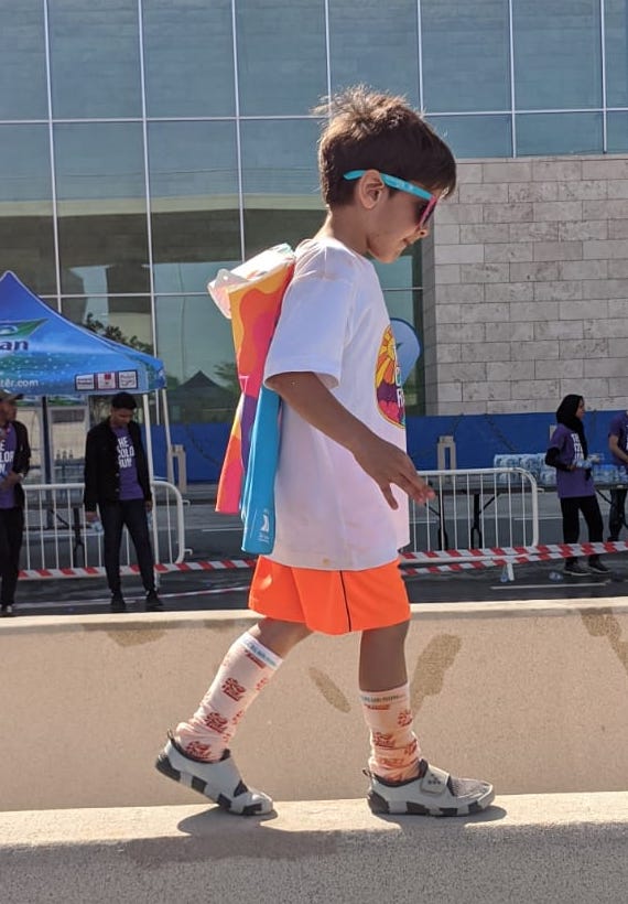
To design a personalinzed sticker, I used a photgraph of my son and traced the edges using Inkscape.
 ---->
---->  --->
---> 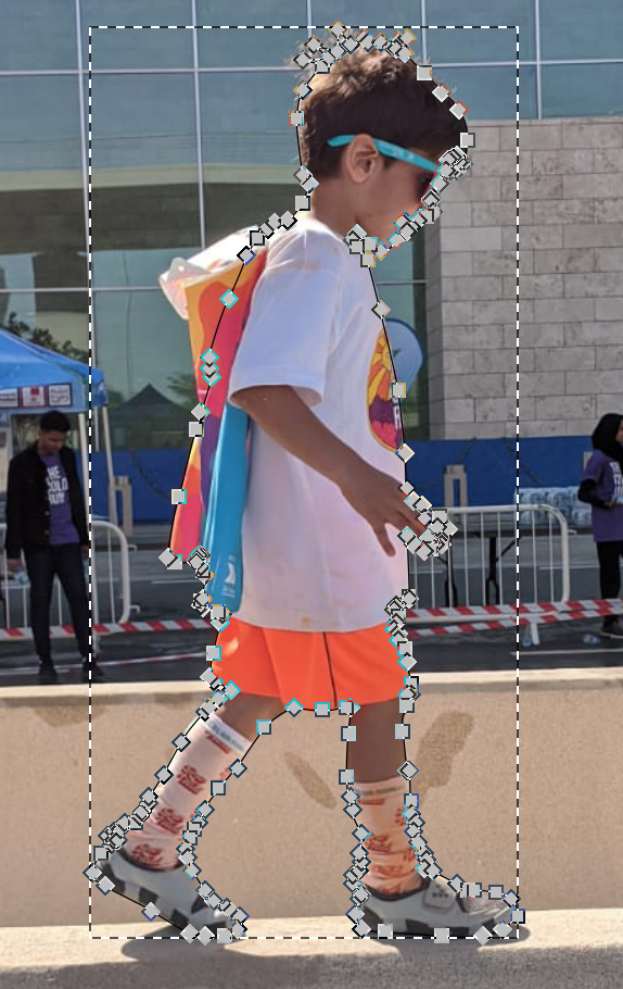
The traced outline was saved as .DXF file and exported to Silhouette software. Where it could be placeed on a 12" x 12" canvas that will be fed into the Vinyl cutter.
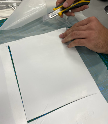
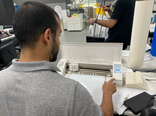
The file was uploaded to the the machine using USB cable and a 12"x12" piece of white Vinyl was prepared and fed into the machine.
 ---->
----> 
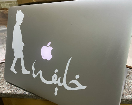
After cutting the Vinyl sheet, the sticker was transferred to my Laptop.
Part 2: Laser Cutter
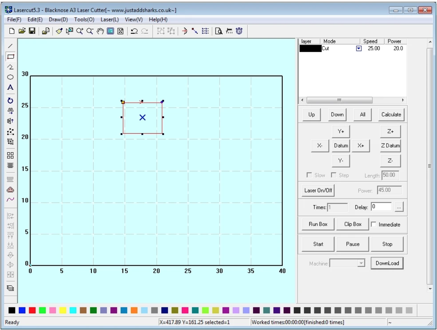
The first step in this assignment was to check the kerf size. The kerf affects the tolerances of the interlocking parts. Not accounting for this will produce parts that were too loose when fitting them together.We designed a simple tool with varying gaps. The gaps went down by 0.2mm.
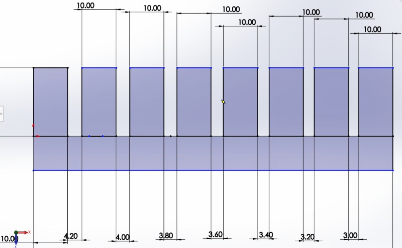
This drawing was sent to LaserCut software (see above) and then was sent to the laser cutter.
We used cardboard. The cardboard piece was added to the machines and the airflow compressor was turned on before starting the machine

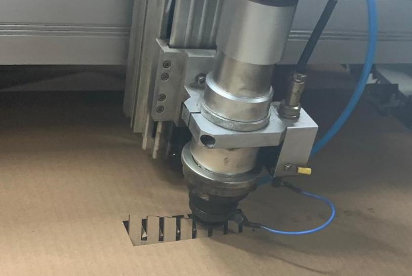

We found that a gap of -0.2 mm is sufficient to hold the pieces together. and this number would be used in other designs.
Cat toy design
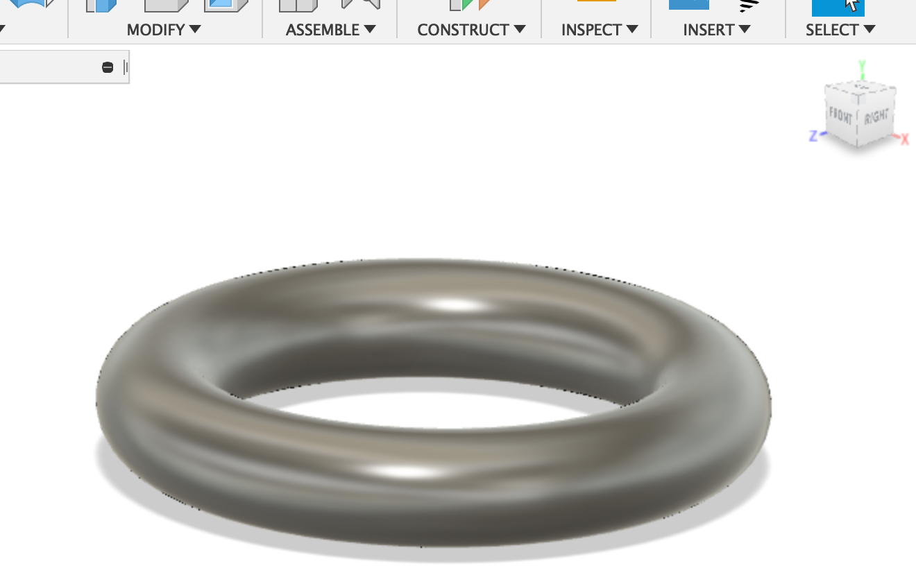
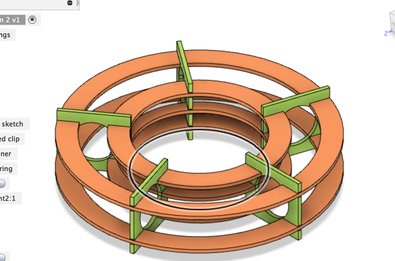
I wanted to make a toy for cats where cats can push a ping pong ball in a circular path. The main challenge was to design the piece with big enough openings for a kitten paw to fit in an push the ball.I tried several designs in Fusion360 and in all of them I used a Torus to represent the path of the ball. The diameter of the ball is 40mm. I designed the torus with a diameter of 43mm
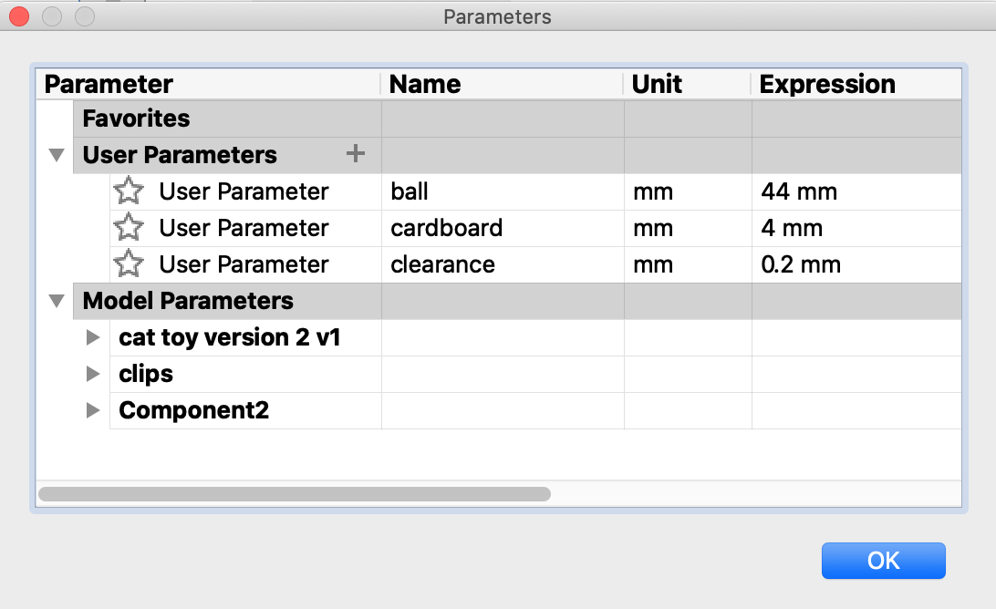
Design parameters were set before designing. This help adjust the parameters as needed in the future.
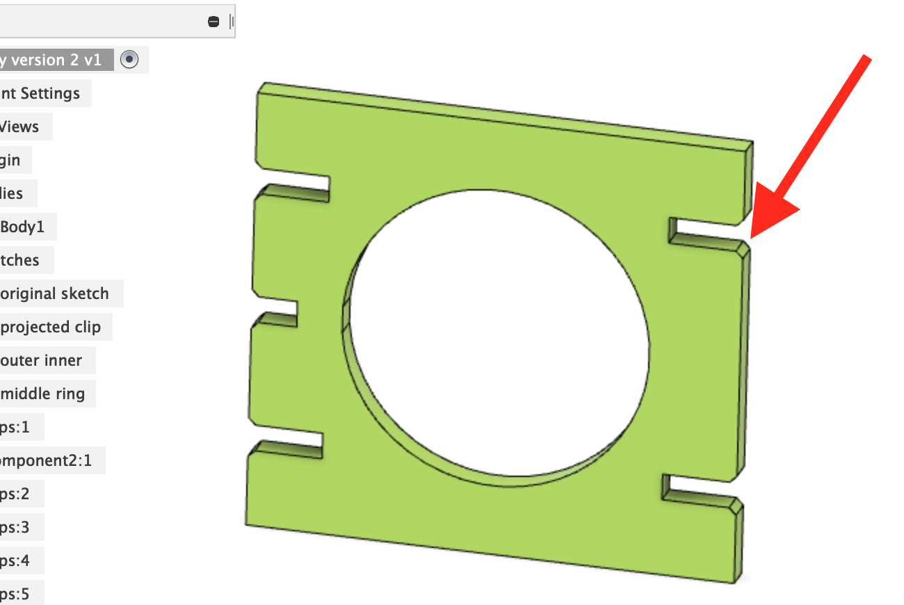
I sketched a square holder to hold the rails for the ball and then revolved the holes around the same axis of the Torus.
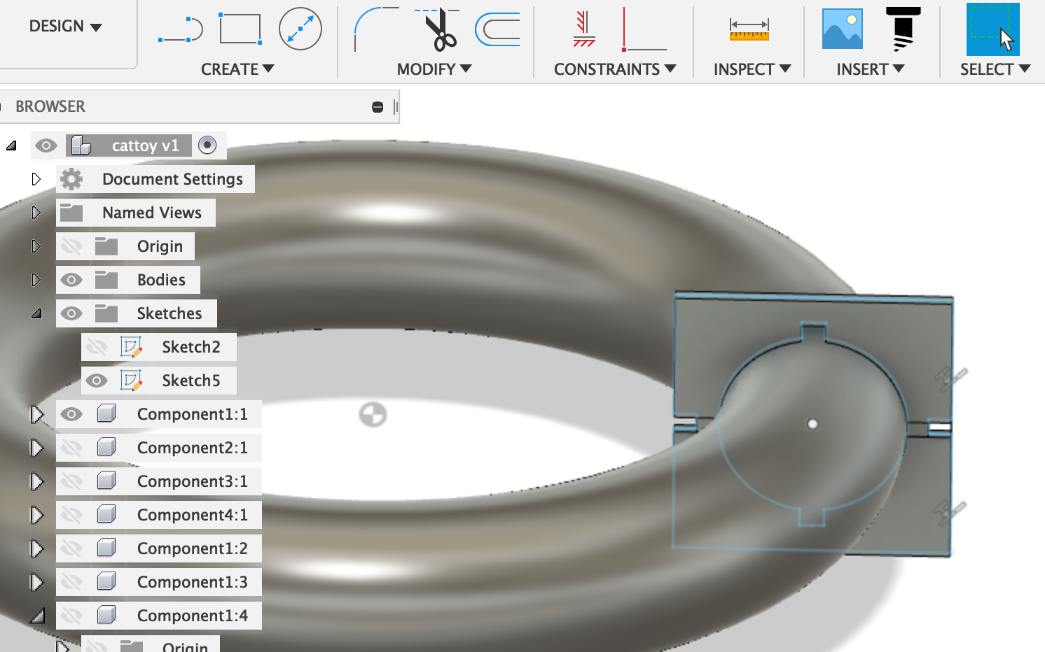
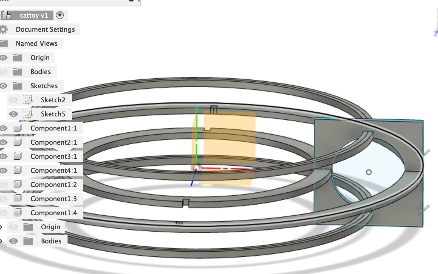
The design shown above had a major fault. The upper and lower rails were designed to fit inside the square holders. However, the were no opening for the rails to be inserted inside the holder.
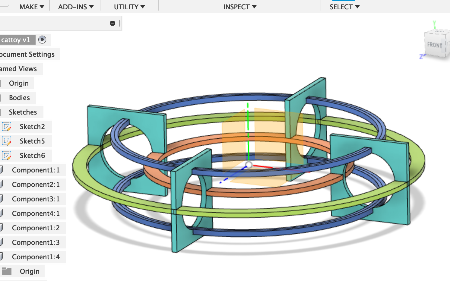
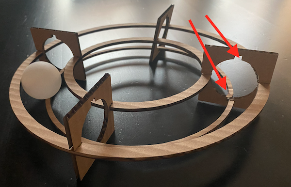
A new design had to be prepared with a new way to attach the rails. The new design had 5 rails and 5 holders. The holders are evenly placed on the rails for increased stability. Chamfers were also introduced to this version of the toy. This helps the piece alignment process to be easier.
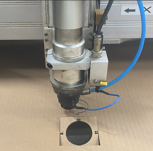
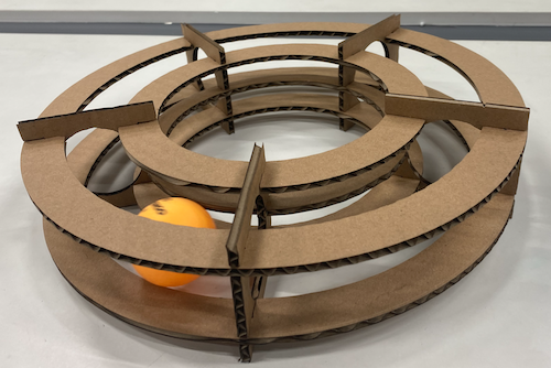
I cut the design using cardboard to test it. The plan is to make it using MDF or plywood.
Note: Many lessons were learned from making this. The first thing i'll fix if I had to make this again is the size of the chamfers. Also, I'd add chamfers on the the rings. This will make it a lot easier to align the pieces while assembling the design
Update: This was tested and the cats in the house are very intrigued by it.
This file can be downloaded for free by clicking HERE