Week 17
Another fun week in Fabacademy! This week we explored machines and differen't kind of mechanical designs and actuation systems. The assignment was to design a machine that includes mechanism+actuation+automation. We had a very wide range of options to choose from. My original idea was to repurpose an old scanner to make a simple Sharpie plotter. However, this would've been a project that required parts parts that are not available in Qatar and ordering them will make us miss the deadline for the assignment.
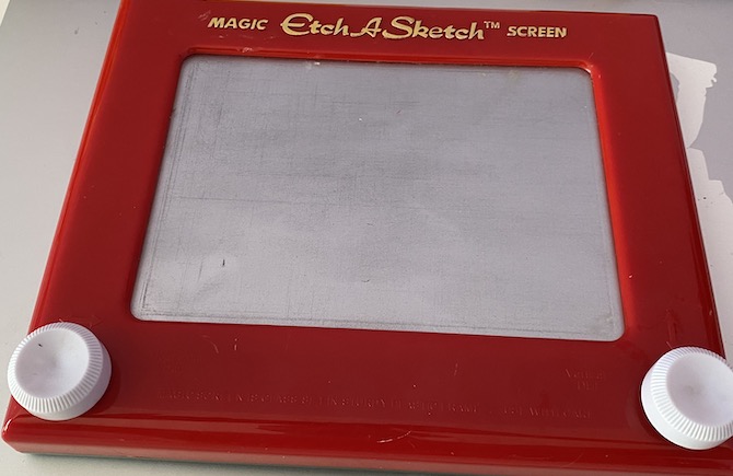
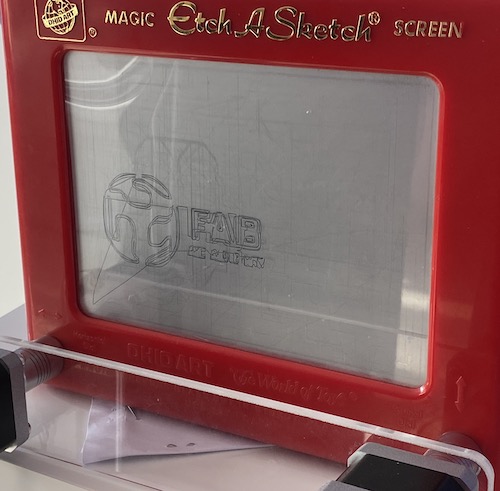
We chose to go with an Etch-a-Sketch plotter.
We Divided the work into 3 parts between 4 people in the group.
- Mechanical actuation of the toy ( Abdulrahmand and Achraf)
- Electronics and motor drivers (Katya Diaz)
- G code generation and programming the controller (Ahmad Almansoor)
Part 1 - Mechanical system
by Abdulrahman and Achraf
There are multiple ways to connect the moors to the etch a sketch knobs. We considered using direct gear connecs, belts, shaft to shaft couplers. The first option would required several iterations to get the gear alignments right. So Achraf designed a belt system where the toy and the motors fit in a frame and connected by belts and geared pulleys.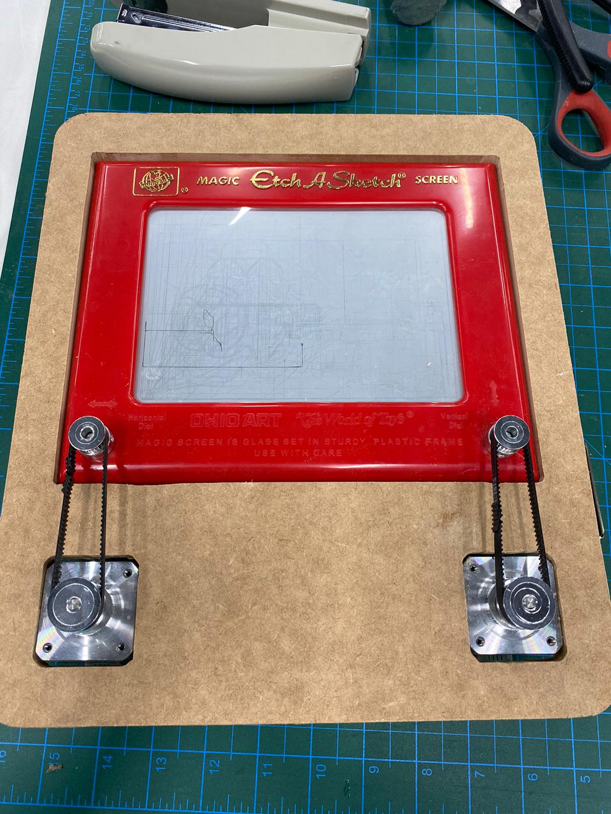
we faced an issue getting a good belt tension even with a make-shift new belts:

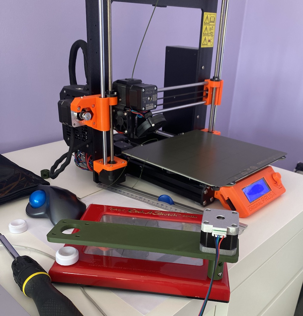
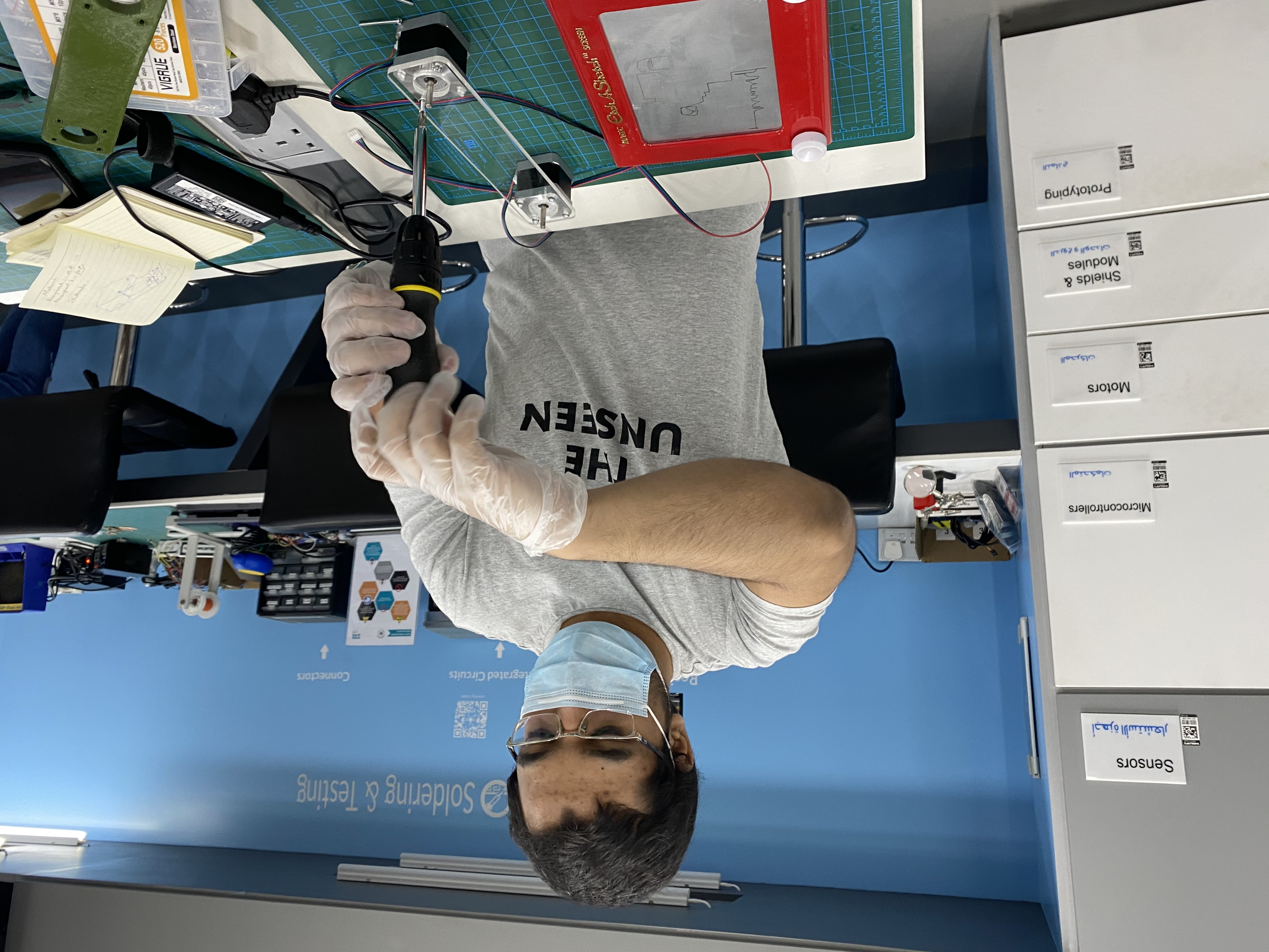
This is where we Ubered the everything to the lab and Abdulrahman was able to cut an acrylic to the same size:
Part 2 - power and electronics
by Katya Diaz
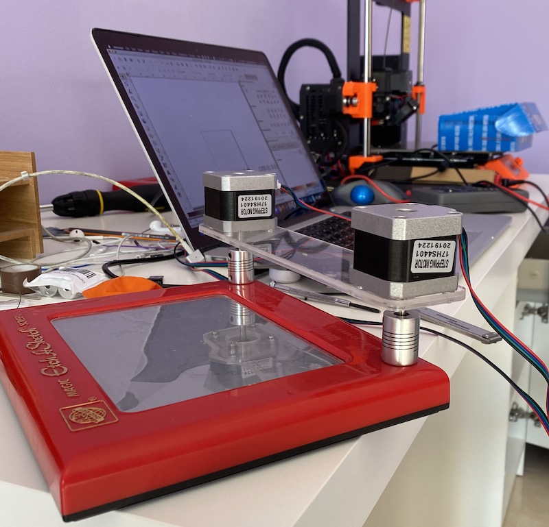
This machine uses two stepper motors to control the drawing head. Each motor will move one axis. To control the motors, we used two Nema17 stepper motors and an Easy Driver to control the motors.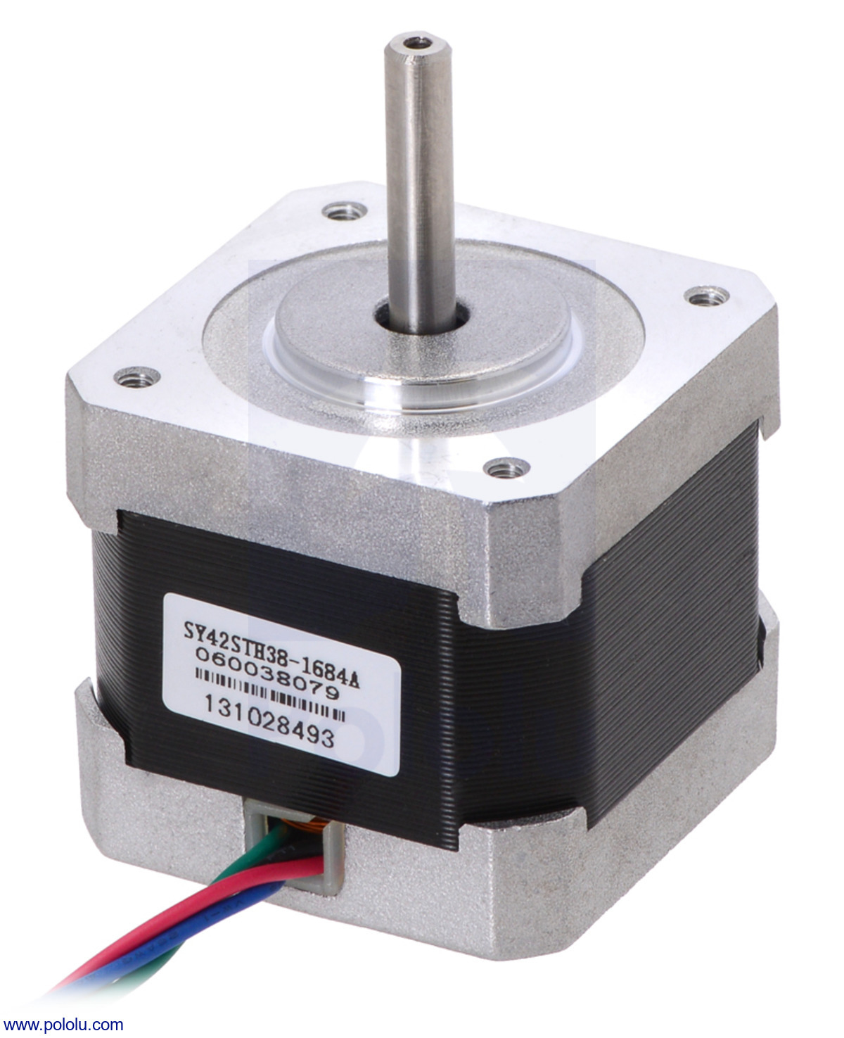
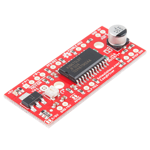
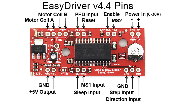
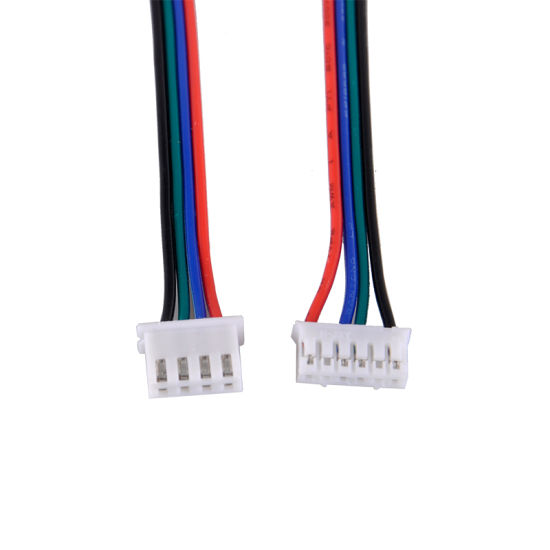
However, enabling the microstepping (by connecting the MS1 and MS2 pins) would be an overkill for this kind of machine. Each motor was connected to a separate easy driver. The motors came with jst sockets that made it easy to identify coil A and coil B on each motor.
the other pins that were connected to the drivers are power in (v and gnd) and the 3 pins in the bottom right corner (GND, Step, Direction). The step and direction pins are how the arduino can control the motor. with every signal recieved the motor moves a step in the direction indicated by the step pin.
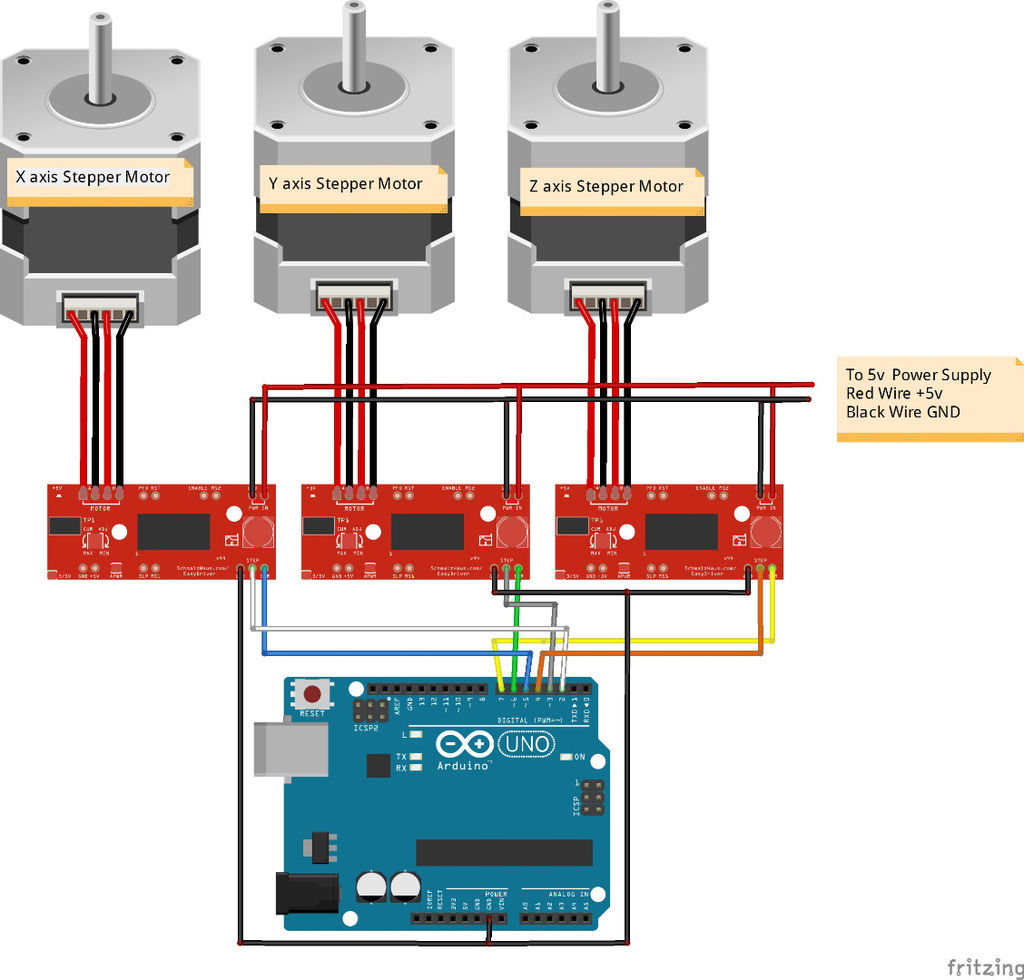
It's important to note here that the picture above shows 3 motors, but we only used the X and Y motors in our project as there was no Z axis to control. It's also important to connect the step and direction pins to the correct pins on the arduino as they will later be used by the grbl controller (see part 3). the pins should be connected as follows:
D2, D3, D4 = X, Y, Z step
D5, D6, D7 = X, Y, Z direction

Part 3 - Software
By Ahmad Almansoor
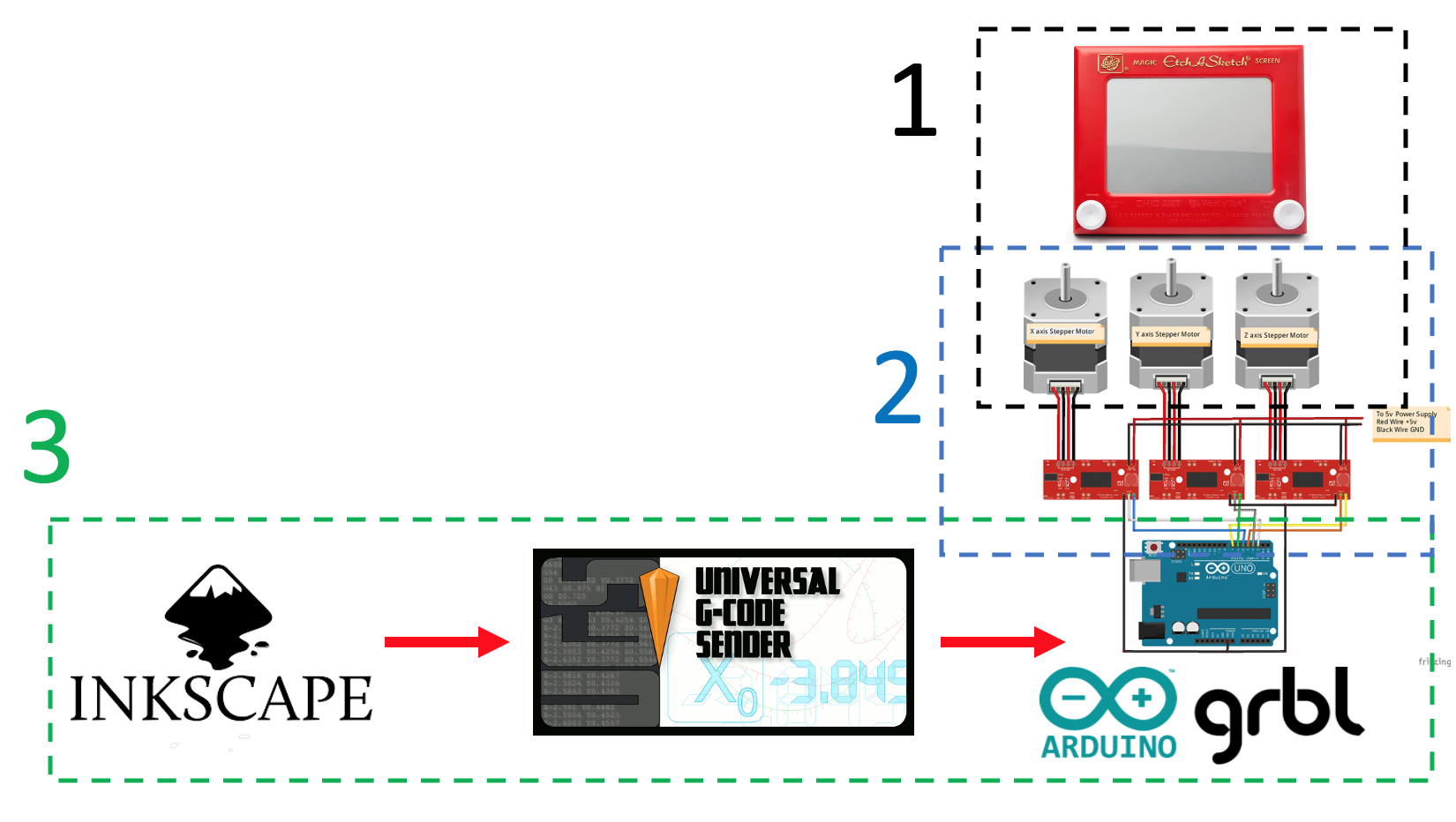
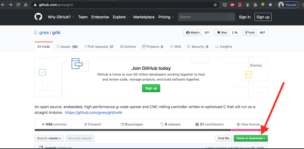
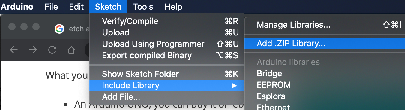
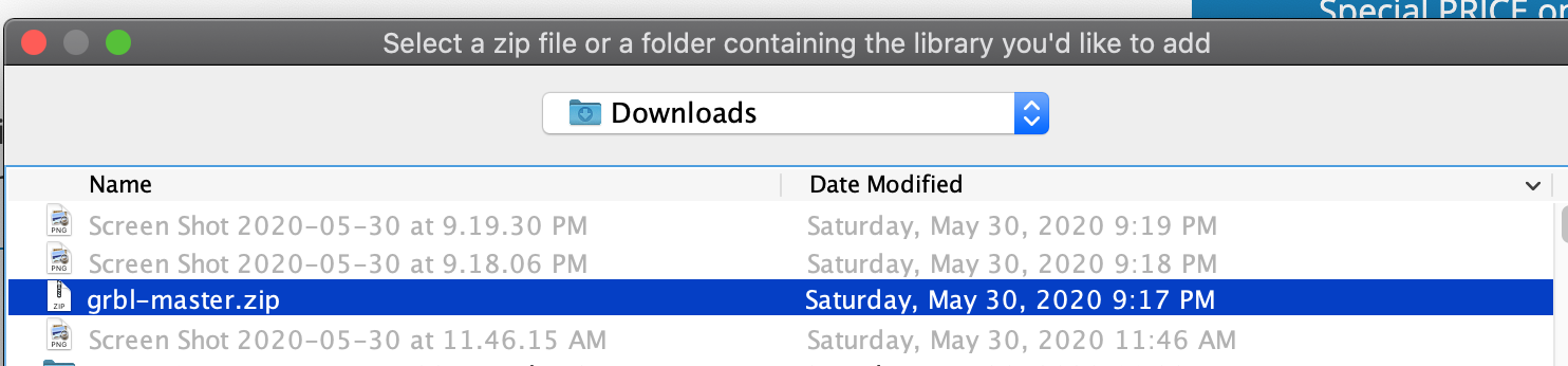
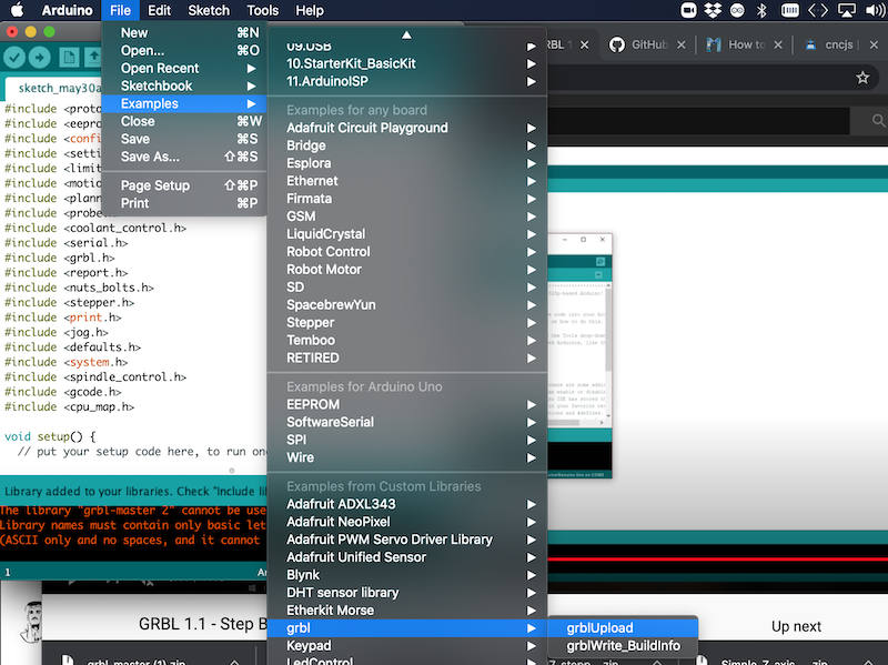
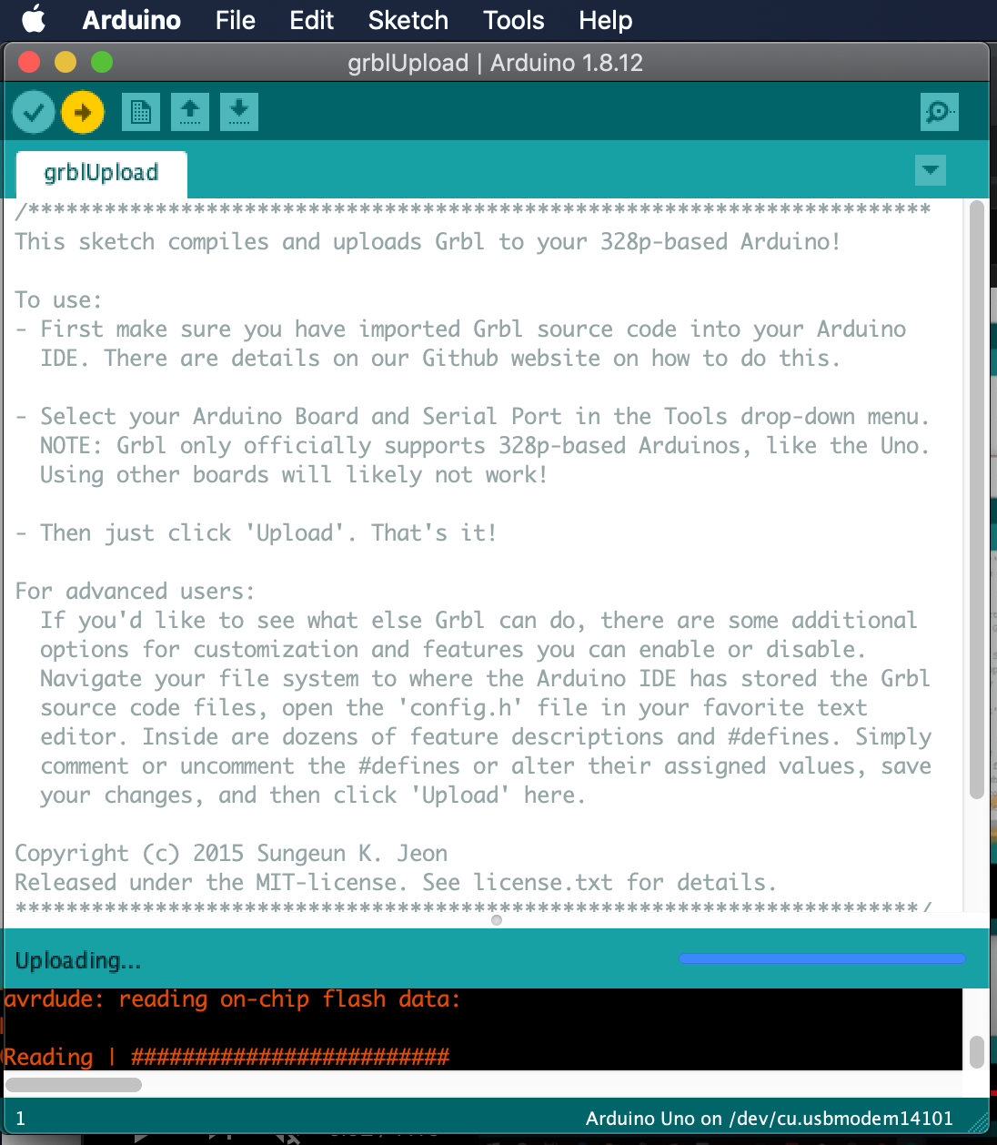
This is the part where the automation comes in. We used GRBL to control our machine. GRBL is an open-source g-code parser and CNC-milling controller. Its runs on Arduino or any other board supporting Atmega 328.first we download grbl library from https://github.com/grbl/grbl.
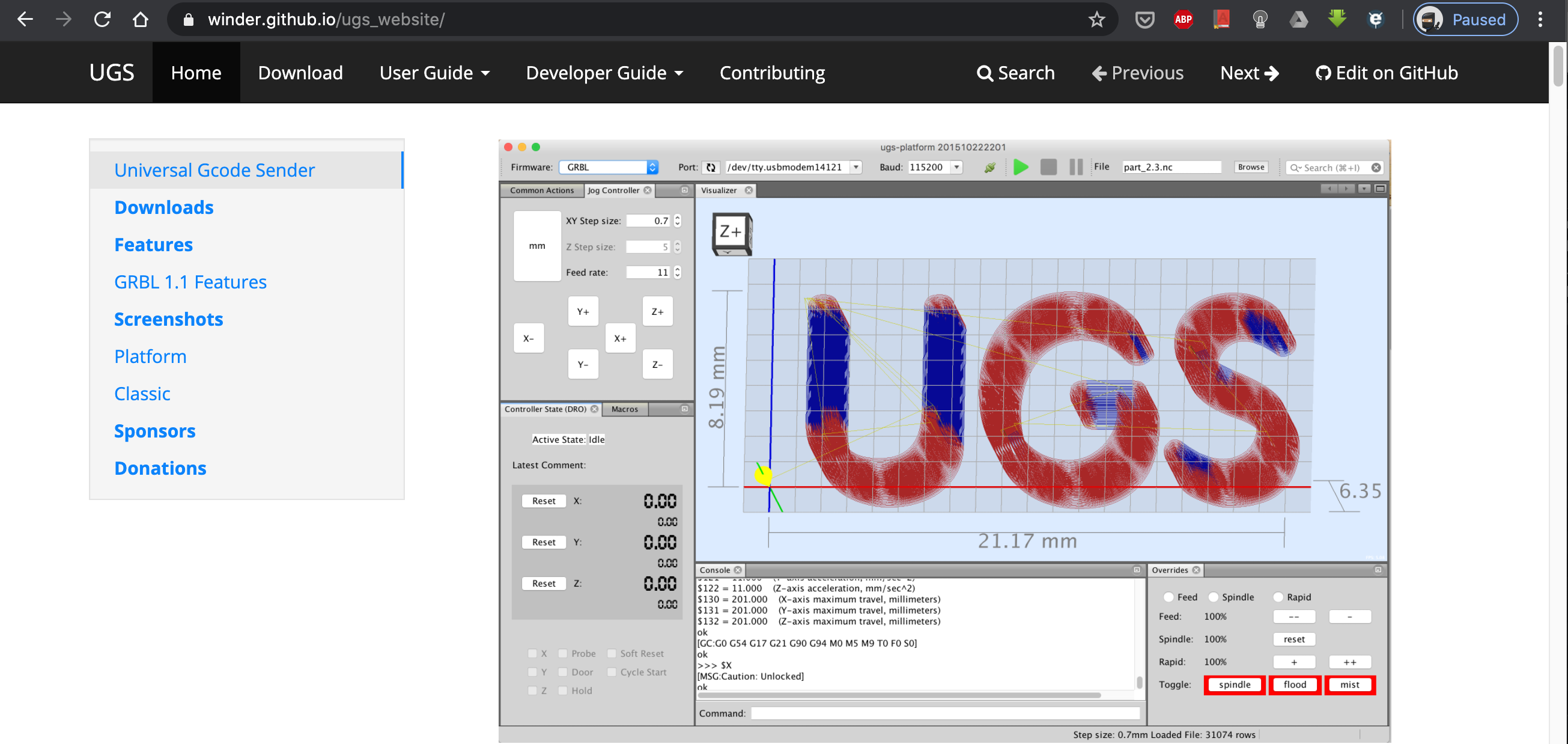
This is done via serial connection and we chose to use UGS (universal gcode sender). There other options available but this one seemed easy to use and suitable for our assignment.
by going to https://winder.github.io/ugs_website/download/ we downloaded UGS platform. There are 2 versions of UGS which have the same function. We decided to use UGS Platform.
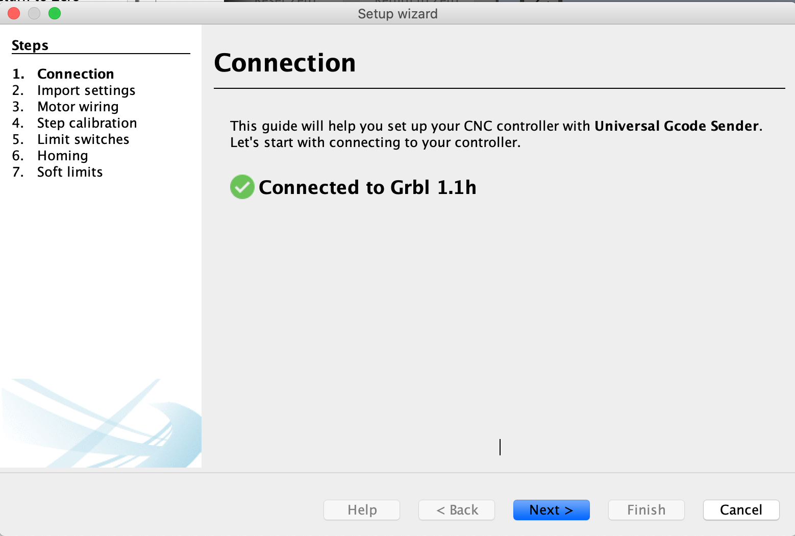

Once this is done, the UGS is now ready to take your G-code. In previous projects, many machines we used had their own g-code generators. We also explored tool paths generated by CAD software like Fusion 360. However, when it comes to 2D drawins, I couldn't find many options. The most popular way (although not ideal) was using Inkscape. Inkscape has an extension that generates gcodes from 2D drawings.
Here is an example on the drawing converted to Gcode:
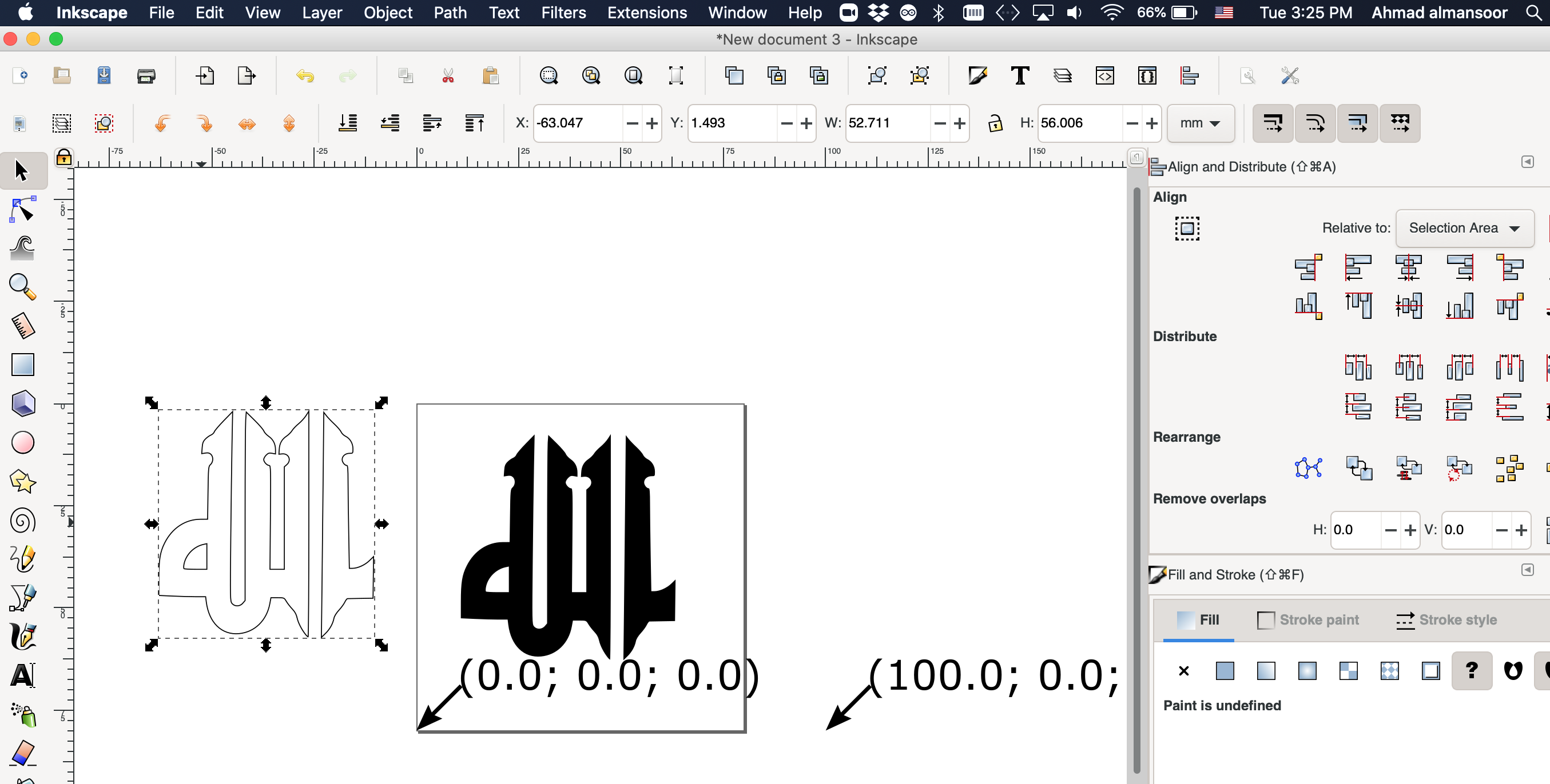
1- open drawing/pic in Inkscape:

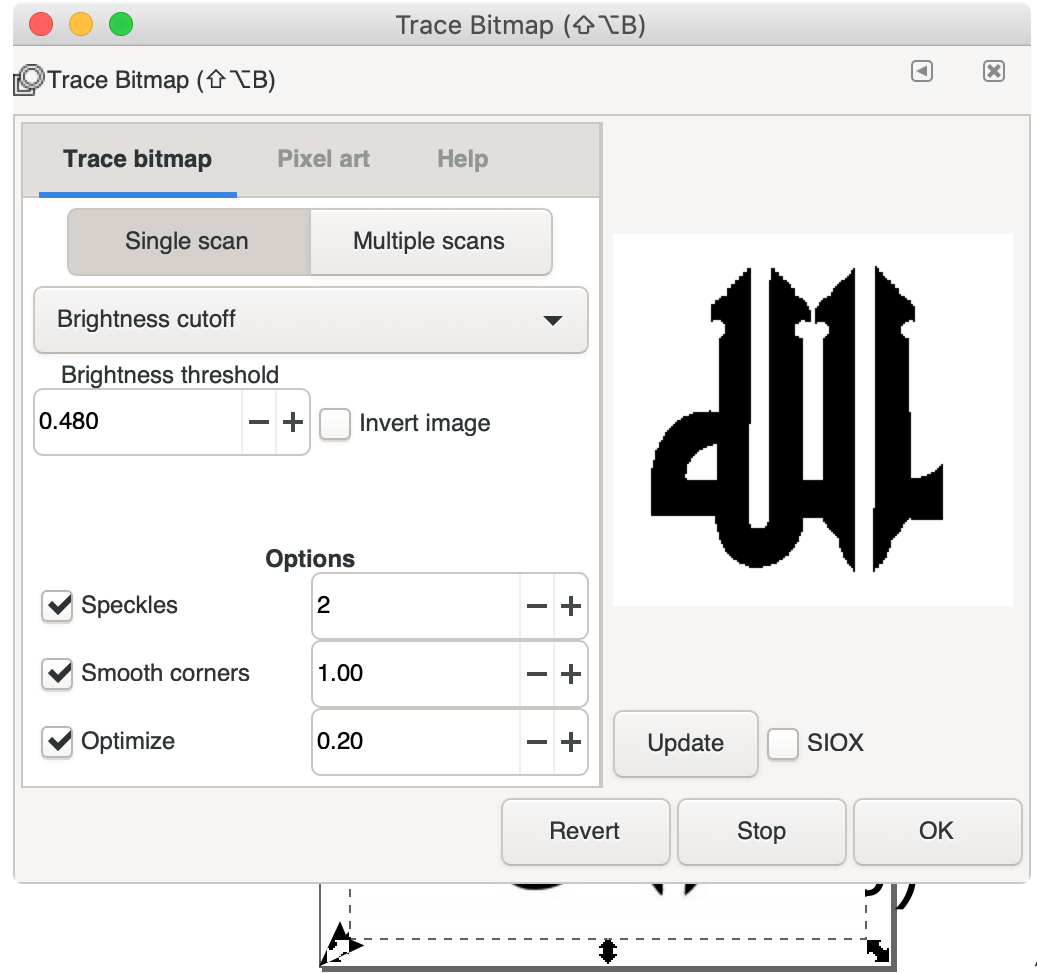
2- trace bitmap (Path > Trace Bitmap)
3- create offset (Path > Dyamic offset)

4- Delete original photo and keep the offset
5- Open Gcode Extension

6- set name and directory of Gcode
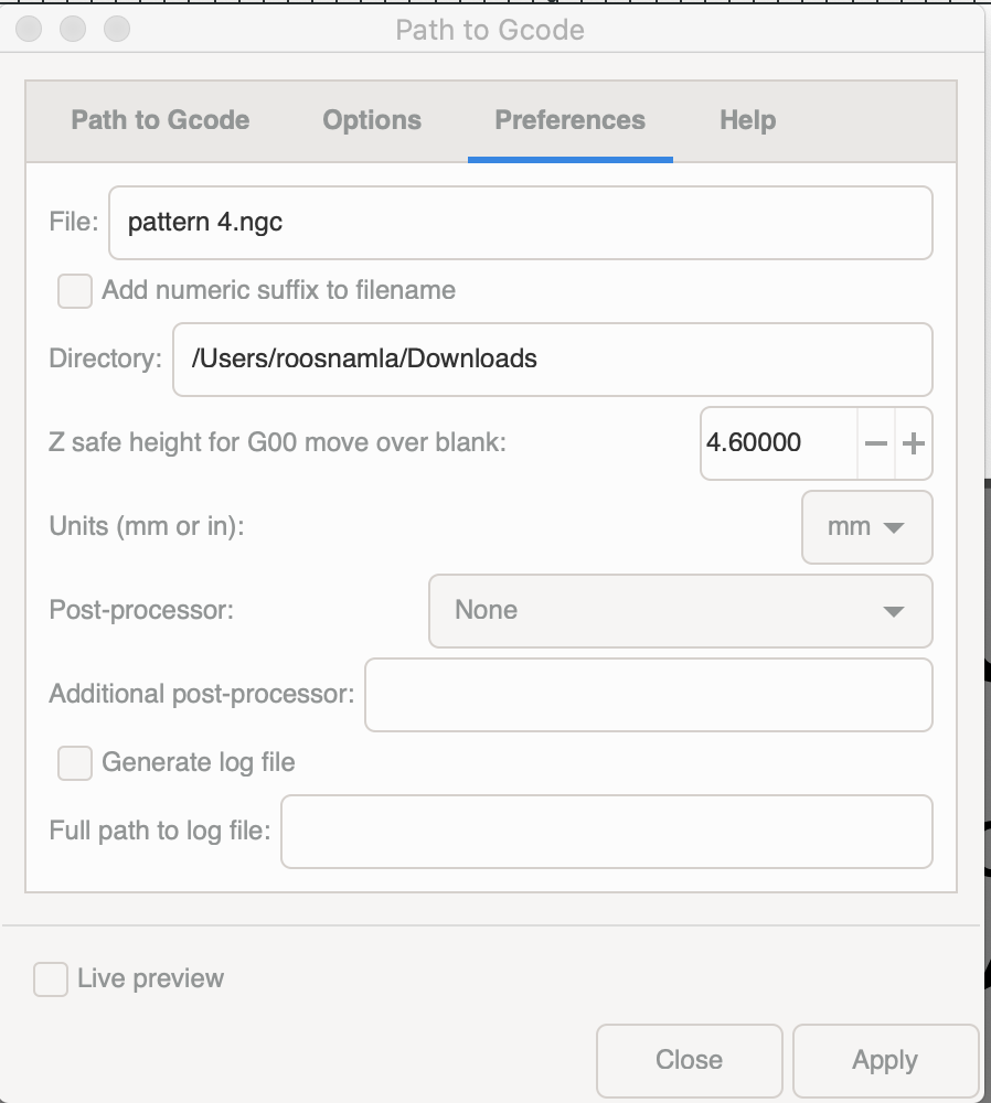
7- go to Path to Code tab and click Apply
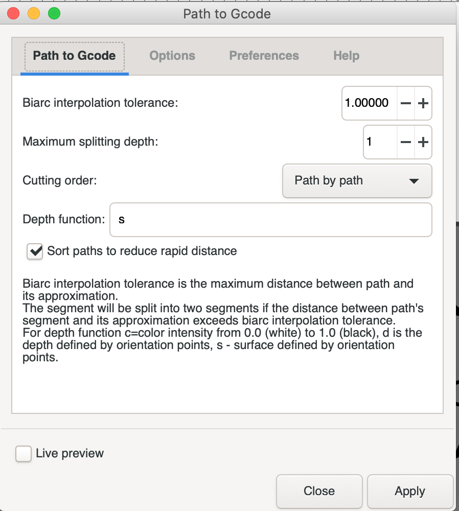
The software will then calculate a G code and send it to the specified directory under the specified name. Note that the tool size was not specified. The software has a default tool that it uses. If you have a different tool and would like to specify it, you can do this under the Gcode extension.
Next we can open the gCode in UGS:
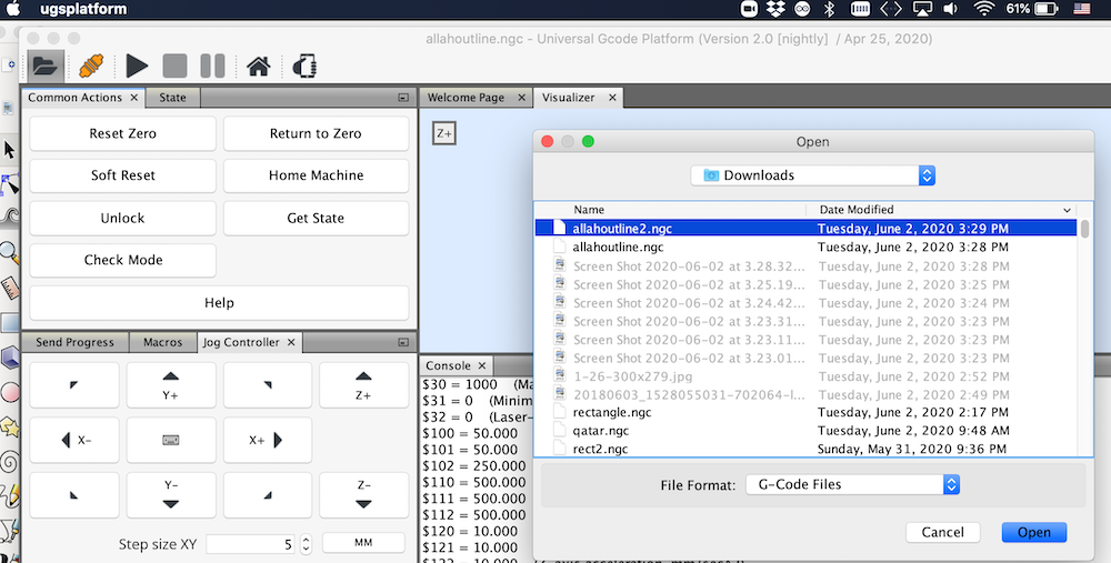
UGS platform has a visualizer that helps visualize the tool and the path. By manually homing the machine and then clicking on Reset Zero in UGS we retered the machine to it's datum.
Then finally we can send the code the arduino/grbl and have the motors follow the code.
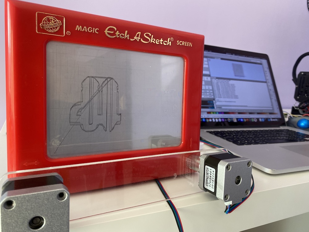
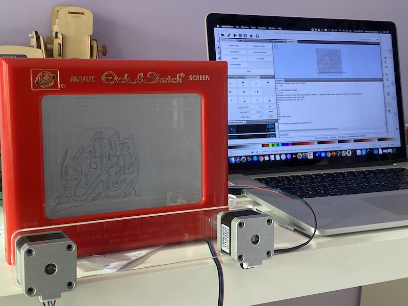
here are other drawings done by the machine:
Lessons learned
Even a simple machine like this one requires a fair amount of planning ahead and designing a good way to actuare the tool. It's abvious that the machine was not perfect. lines shifted a little. Inicially we assumed this was because the couplers might be slipping but the issue persisted even after tightening the lock screws on the couplers.
Etch a sketch is a toy and it has a some hysteresis. This can be felt even when controlling the machine sby hand.