Week 13
This week was a very informative one. Most of the information that was presented was new to me and I liked learning about different communication methods. The assignment was to design, build, and connect wired or wireless node(s)
with network or bus addresses. There was a group assignment to send a message between two projects but, unfortunately, under the current circumstances this would've taken more time than we could afford.
Individual assignment
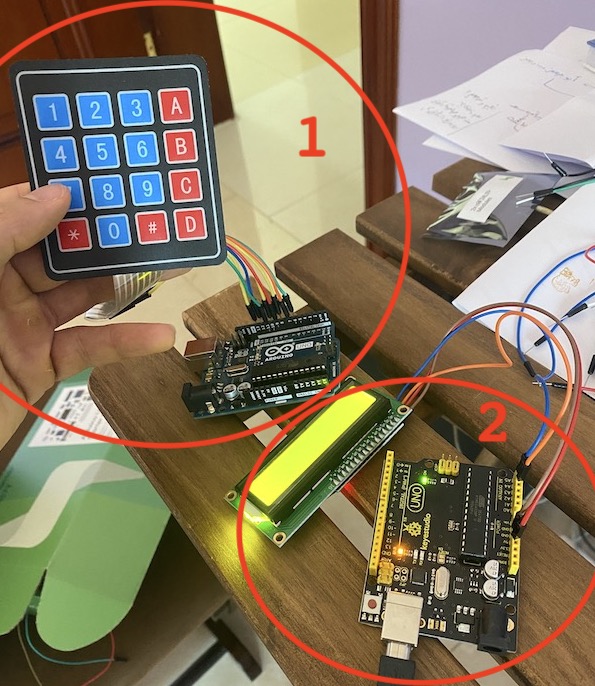
Like mentioned above, I used a keypad to communicate with an LCD that is connected to a differen't Arduino. I'll try to go throught the steps of connecting the two devices wirelessly via nRF24L01.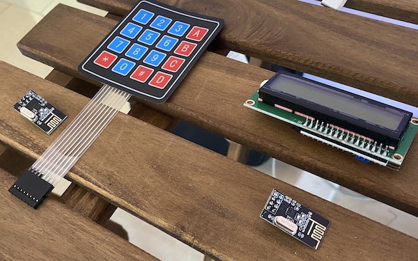
The library (shown below) does a great job organizing the pins and the buttons.

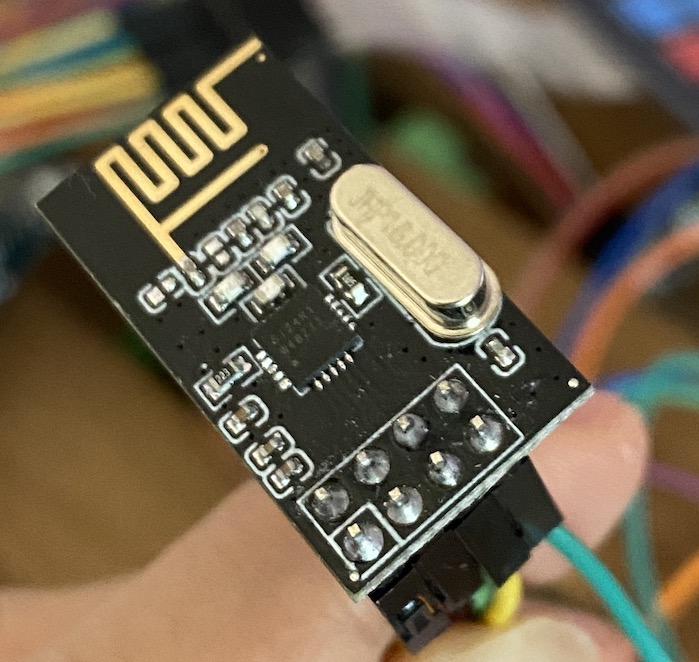
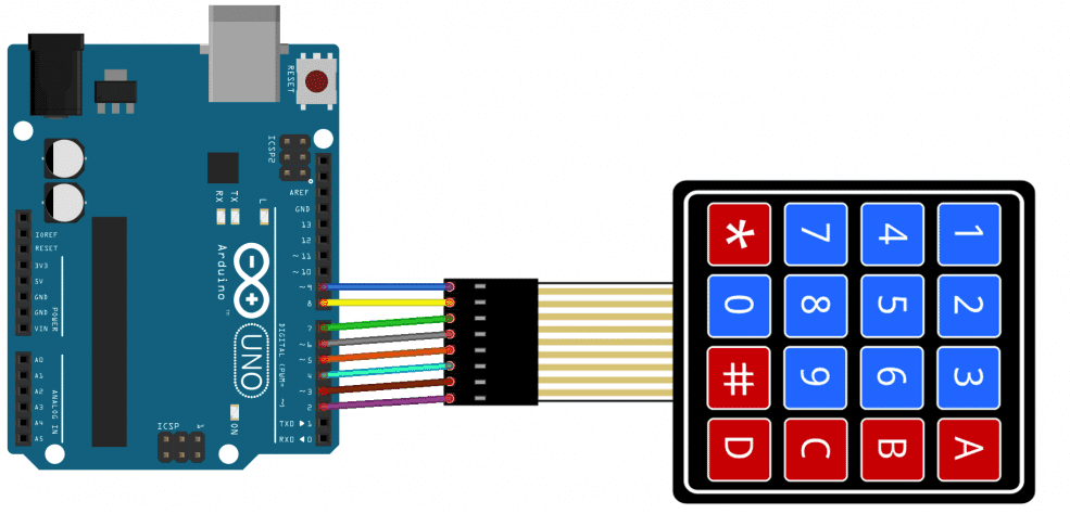
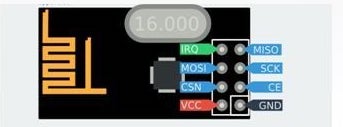
That's all it takes to connect these devices to the arduinos. Now comes the part where we will have to send data between the two arduinos. The nRF24L01 uses SPI connection to connect to the arduino. The wiring is shown below:
After connecting the modules on both arduinos, it's time to write the code for each one. One will be the TX (transmitter) code and the other will be the RX (received) code.

Transmitter code:
Receiver code:
Here is a video showing the final result of the assignment:
Lessons learned
There were some hiccups along the way while trying to figure out how to do this assignment. I had to look at multiple examples in order to learn how to use the library properly. Also, I still need to learn how to send mupltiple digits to use, for example, as passkey. The assignment currently sends 1 character at a time.
I will try to connect a servo and control it via nRF24 just to keep improving the assignments i've been working on.