Week 10
The assignment for this week is to add an output device to a microcontroller board you've designed,and program it to do something. There is also a group assignment which is to measure the power consumption of an output device.
Now, output devices can be anything from motors, speakers, solenoids, displays..etc. In the prviouse week I added a display to my sensor and display the readings.
This week I decided to control a servo motor.
Group Assignment
I would've loved to measure the power consumption of a stepper motor. I'm curious to see how much current the motor draws when it's shaft rotation is resisted. Unfortunately, we have no lab access at this time, so it'll have to be the first thing i'll do when I get back in lab.Individual Assignment
Servo motor
Here, an SG90 Micro Servo motor was connected to an Arduino Uno. The servo is connected to 3 wires, power, ground, and signal.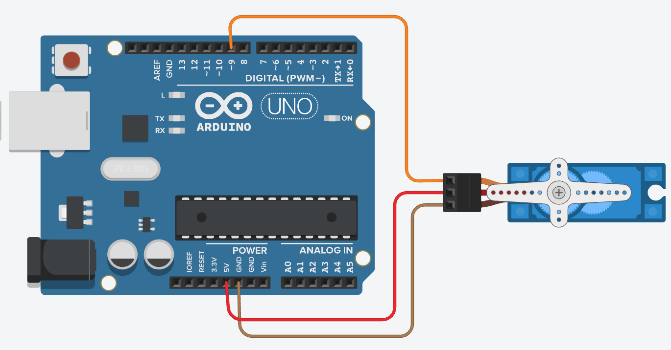
This type of motors is normally used to point at a specific angle. So, it would rotate from 0 degrees to 180 degrees.
The way it reads this is by using PWM (pulse-width modulation) where the signal going in will vary in width to control the position.

Now to avoid the hassle of writing a code that'll control the servo to move to the decided angle, servo.h library comes preloaded in the Arduino IDE. I will not go throught the steps of including a library in the code as th was mentioned in Week 9 assignment.
The servo library is simple and straight forward. after declaring the servo pin and the angle, the servo will move to this angle.
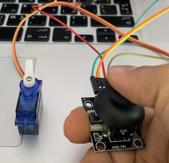
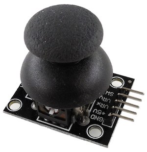
I've wanted to try to Joystick controller. in the video shown, an HW-504 joystick module was used. This device outputs 3 signals; X-signal, Y-signal and switch signal. In addition to these 3 wires, the module needs a 5v power and ground connections.
In my example I did not need to use the switch data so I only used the Y signal.
These wire was connected to anaglog pin A1 on the arduino since the signal will be an analog signal. Then the code was uploaded to the arduino:
Here is a video showing the final result of the motor after the code was uploaded to the Arduino Uno.