What? Final project?
"This is your opportunity to demonstrate synthesis of skills you developed in the previous weeks. Your goal is to keep it as affordable as possible. Design and fabricate your own parts instead of buying off-the-shelf components. Each student, whether working individually or in a group, must prove mastery of the skills gained during the program." Fab Academy Documentation 2020
Requirements for Final project
- Create your own integrated design
- Demonstrate 2D & 3D modelling capabilities applied to your own designs
- Select and apply appropriate additive and subtractive techniques
- Demonstrate competence in design, fabrication and programming of your own fabbed microcontroller PCB, including an input & output device
Project presentations
Presentation slide

Presentation video
Preliminary ideas for final project
First idea: boombox
Idea for final project My first idea was, hmm, familiar and intuitive everyday tool. First I thought to do boombox, portable audio unit. I have got a lot of experiences about Volumio distro on Raspberry Pi computers. I did plan to design unit around that, but then I noticed that readymade boards are not accepted or recommended.
Second idea: mobile interface to internet-of-things sensors
My second idea was related to internet-of-things sensors being installed everywhere at our uni. I did plan to design mobile "interface" for reading sensordata and watching trends from certain plate at the university of botanical garden. Well, I wasn't very happy with that either.
Third idea: Four wheeled robot, which is controlled by AI. WINNER!
My third idea was exciting enough to get motivated. I had a meeting with one local entreneur about using AI in affordable robotics and coding. They also participated in our local hack weekend in FabLab where they did built first prototype of the gadget. Our meeting was about possible project and research collaboration, but I realized that this will be also my final project
Backround for the project: Alvin AI and Robot arm
I met mr. Tommi Mänttäri, inventor of Alvin AI engine, autumn 2019 in workshop at the university of Oulu. At that time they were developing use case where Alvin AI was used in english teaching. For me it was, ok, but not very spectacular. However, something bigger was around the corner, but I didn't know it yet..
In the late 2019 and early 2020 I got messages from mr. Mänttäri, but also from different other sources about the project where local community of engineers, researchers and teachers are aiming at develop robot with AI for school children.
WOW. They explained that in their view pupils would design and build their robots by using digital fabrication technologies. Price of the components would squeezed as low as possible and documentation would be shared as an opensource and creative-common licensed materials. YEAH!
But best part was that in order to keep design simple, robot would rely on smartphone which would be the "computer - brains" of the project. Robot itself would have simple ESP32 chipset, which would communicate with the mobile phone via wi-fi, bluetooth or similar. ESP32 would control servomotors and read sensors, but based on the information given by the programs from the phone
At the moment team in Oulu is developing "robot arm" which share same ideas. They have already done working prototype. My aim is to remix this idea so, that I will design car instead of arm, but main idea is same: children teach AI, which controls the robot itself instead of coding robot.Idea is to create low-cost, opensource materials for learning of robotics, artifical intelligence, computational thinking, digital fabrication etc.
My Final project: remote controlled cardboard car
Ultimate aim: create rc car which is controlled by artificial intelligence on mobile device
Because of the spiral design process, I have given up with this aim. Unfortunately. I will continue working with this theme anyway after Fab Lab.
I had vision to design AI controlled car, which would use main components and ideas from Alvin AI/Simua technologies robot project and would also contribute into that project.
Because of the limited timeframe and parallel Alvin Ai robot arm development project, I decided to simplify little bit my design. In practise, Alvin AI has now capabilities to control robot arm by using machine vision (these components are running on android phone and robot control is done by using ESP32)
In practise, I won't use artificial intelligence components in project, which are 1) Use of AlvinAI engine 2) Use of Nasa Vision workbench. Yet, I won't use PCB designs and PCBS by Simua/Alvin AI, but use same IoT platform (ESP32) to control my car. It's easy to utilize alvin AI engine later on just by changing the codebase of ESP32.
However, I will contribute all my designs to Alvin AI/Simua tech co-design project under creative commons lisences they are using. Also I will continue later on with hardware and software components provided by them.
Realistic spirals of the development
Because of the time limits, I will aim to basic level, but design PCBs so that e.g. adding neopixel lights it's possible implement later on. Also car chassis will be designed so that mobile phone can be put into car (in the context of Alvin AI phone has AI and machine vision components)
Basic level: to design and create simple cardboard car with remote controllerThis level is the starting point for the project: to design cardboard RC car which can be controlled with mobile phone.
Intermediate level:Continue from the basic level with more advanced chassis for the car (complex 3D design) or autonomous driving mode by using ultrasonic sensor or neopixel lights for driving / alarm lights
Ultimate level:Use codebase from Alvin AI project and create autonomous car which uses artificial intelligence for controls.
Related weekly assignments
- Embedded programmingto get familiar with ESP8266
- Input devices: to get familiar with reading sensors (temperature, ultrasound)
- Output devices: to get familiar of programming servos and motors
- Interface and application programming: Mobile phone as user interface for ESP8266 project
- networking and communications: How to use MQTT and Node-RED for communicating (explorations for the possible controls: learning basics)
- Machine designCardboard machine (in our case it was robot, but I wanted to try cardboad as machine material
Sketching and planning the cardboard car (it would be like that.. -phase)
- Electronics desing:
- voltage stripdown PCB (if not integrated into ESP32 board)
- motor controller PCB
- ESP 2866 board
- Car chassis (body) and structural frame design
- Powertrain and steering design: servo(s), wheels, axels and motor
- Controls and Code: ESP8266 code and remote client (mobile phone app)
- Integration and decoration: putting everything together
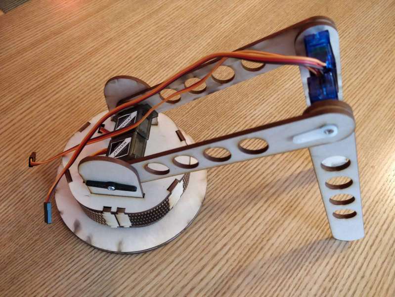
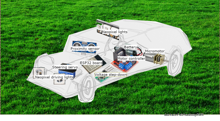
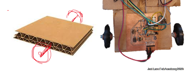
Main components of the car (left picture):
- Cardboard body and chassis: Not explored in details here, but it's material for car
- Powertrain: 2x Micromotor with gearbox (needs motor controller to be operated)
- Steering: Servo for steering (can be operated from ESP32, but needs voltage step down circuitry)
- Motor controller: H-Bridge board to enable direction change and speed control (for micromotors)
- Voltage step down circuit: To change voltage suitable for servo steering and ESP32 board (for ESP32 and servo)
- ESP32 Board: Brains of the car: processor, wireless communications and I/O with sensors, motor controller and neopixel lights (reservation)
- Proximity sensor: Simple proximity sensor which e.g. transmits proximity information to ESP32
- Neopixel lights: Controllable LED segments, which can be used e.g. driving lights (option/reservation)
- Battery: Not explored yet, but in the earlier similar projects voltage has been higher than servo/ESP32 can tolerate (need for voltage stepdown circuitry)
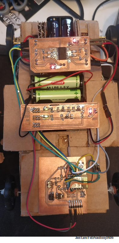
1. Requirements for electronics
Remote controlled cardboard car does need three major components to be remote controllable: 1) main unit (wireless communication, processor, I/O connections to other parts of the car etc); 2) motor controller (direction of the DC-motor, speed); 3) power strip down circuitry (3v for main unit, 5v for motor controller unit, steering servo and ultrasound sensor) and 6v for polulu minimotors.
This picture explains how components would be wired together (NOTE: this uses readymabe PCBs, so it is only for illustrative purposes)
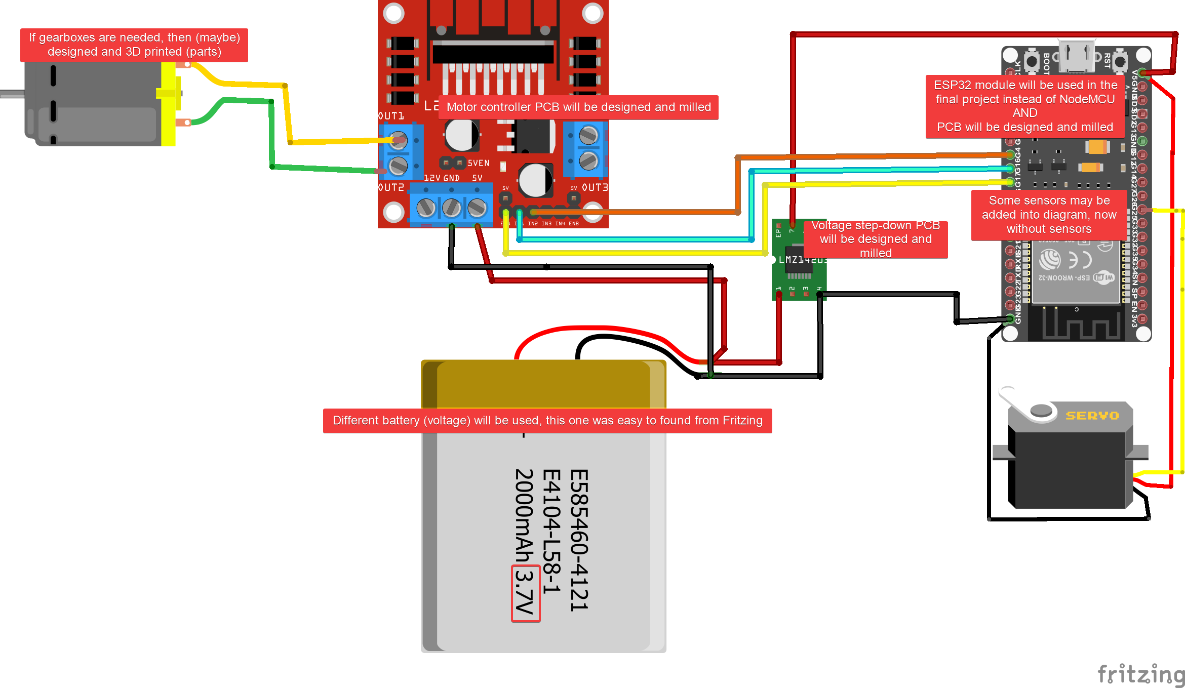
I got this idea for cardboard car through Alvin AI robot project. In that project ESP32 is used as a controller for different inputs and outpus AND it will be controlled from the more advanced Artificial Intelligence software from the mobile phone. Because of the spiral development, I had to start from the more generic level. So, because there is a lot of examples, tutorials etc for older ESP model, ESP8266, I did chose that to be main unit in my cardboard car project. Also I had to leave my dreams about AI controlled cardboad car for the future. If I have time, I will create simpöe autonomous mode for the car by using ultrasonic sensor. So far now, it will be used just as sensor and values should be readable via screen of the mobile phone
I/O lines between the main unit and other electronic components:
- ESP8266 board: I/O and power pins
- 3.2VIN: power for the board
- GND: ground
- Motor 1 Enable: GPIO pin out on ESP8266 AND input EN1 on motor controller
- Motor 2 Enable: GPIO pin out on ESP8266 AND input EN2 on motor controller
- PWM motor 1: PWM pulse out (forward) pin on ESP8266 AND input A on motor controller
- PWM motor 1: PWM pulse out (backward) pin on ESP8266li> AND input B on motor controller
- PWM motor 2: PWM pulse out (forward) pin on ESP8266 AND input C on motor controller
- PWM motor 2: PWM pulse out (backward) pin on ESP8266 AND Input D on motor controller
- Steering servo: servo GPIO pin out on ESP8266 AND XX on servo
- Ultrasonic sensor Trigger: GPIO out on ESP8266 AND trig IN on ultrasonic sensor
- Untrasonic sensor Echo: GPIO in on ESP8266 and echo out on ultrasonic sensor
Motor controller board: I/O lines and power pins
- 5v VIN: power for the motor controller
- 6-12VIN: power for the motors connected to controller
- GND: ground
- EN1 and EN2 inputs: ESP8266 activates motors 1 and 2 by setting these inputs HIGH
- Inputs A and B: ESP8266 tells to motor controller direction of the motor 1 by setting A high and B low or vica versa
- Inputs C and D: ESP8266 tells to motor controller direction of the motor 2 by setting A high and B low or vica versa
- Motor A1 and A2: outputs to DC motor 1
- Motor B1 and B2: outputs to DC motor 2
- Voltage stepdown board: power pins
- 6V IN: Power from the 4x1,5 battery box
- 3,3V OUT: Voltage for ESP8266 board
- 5V OUT: Voltage for motor controller, steering servo and ultrasonic sensor
- 6V OUT: (direct connection to 6 VIN) voltage for DC motor 1 and 2
2. Requirements for car chassis (body) and structural frame
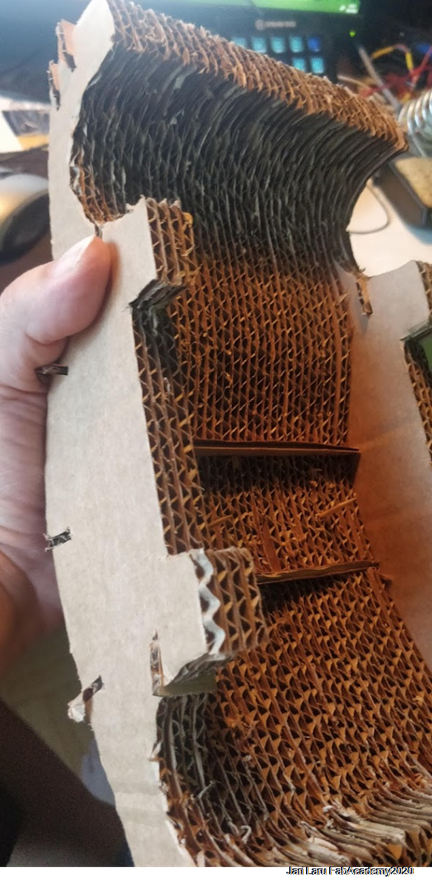
It's clear that cardboard car needs cardboard chassis and structural frame. Such body components should be easy to lasercut and easy to assemble in order to use this same RC car idea in K-12 (pre-service teacher) education.
I have got suggestions from Fab Lab Oulu staff both to fold cardboard when possible, but also to use parametric design for slot joints.
Personally I have been cautious about the fact that all electronics, motors, servo(s) etc. need sturdy cardboard platform. So I will put a lot of effort for designing cardboard parts of the car.
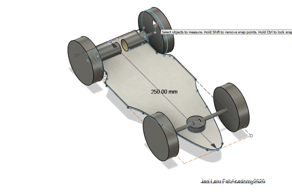
To support this sketching phase of the final project, I did draw "mule version of the cardboard car" (see week: )week 3. Computer Aided Design (2D and 3D) This will be used to fit components into body and exploring the measures for the actual car desing.
This can be also lasercut if time is avalailbe, but also mere Fusion360 measures are enough to show how different parts may fit into car frame.
3. Requirements for powertrain and steering
Alternatives for steeringIn order to control heading of the car I need either servo controlled or h-bridge controlled steering.
Servo would give more accurate steering experience, while motorl controller H-bridge (L293DD) can be used also to change direction of the one of the two motors (ie. turn the vecicle). Use of H-bridge can be faster and easier to implement, because front wheel fittings will be very simple compared to servo steering
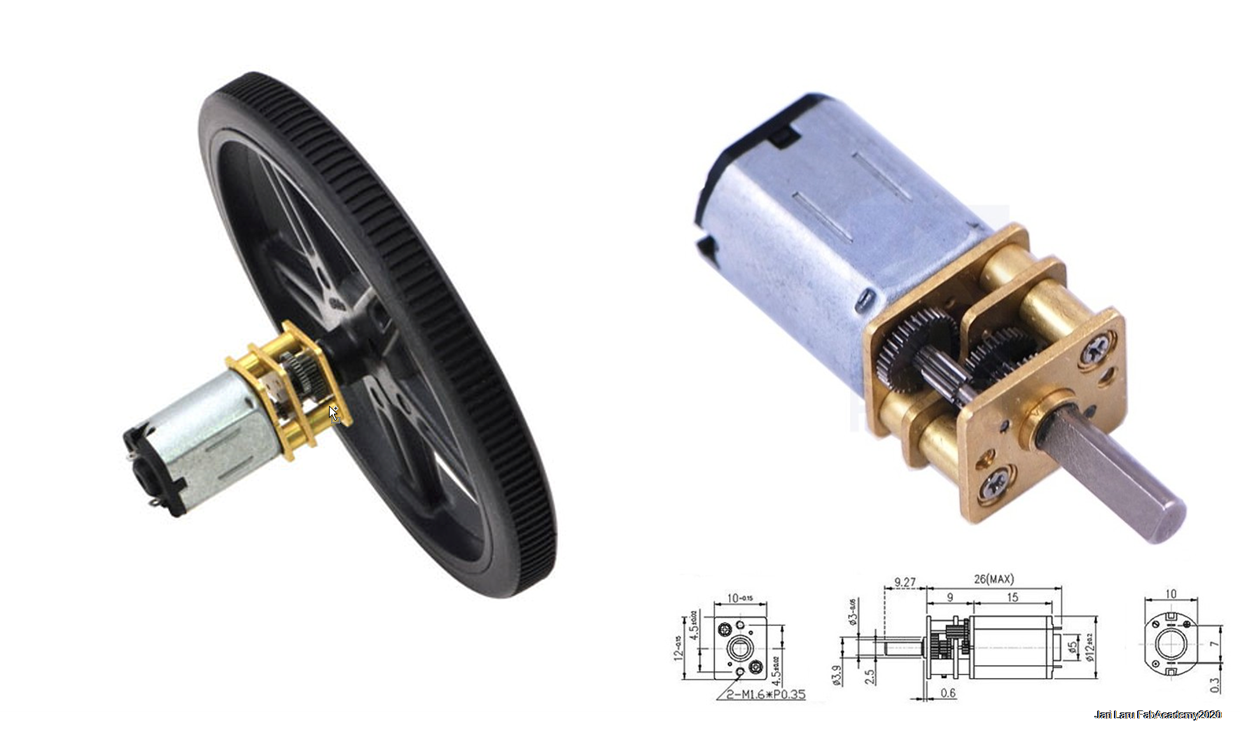
Powertrain for the carIn order to speed-up the design and development process powertrain will be based on the motors with integrated gearbox. In the Fablab Oulu we have Polulu minimotors, so I may end up to use those motors
4. Requirements for controls and code
Alternatives for Remote ControllerBecause aim of the project is to build remote controlled cardboard car, it's pretty clear that one part of the project is to explore how to create remote controls for the car. In the world of internet-of-things, it's pretty obvious that mobile phone will be the device for remote controls
UI Mockup: Fab Remote. Responsive www-application for controlling the car (right picture)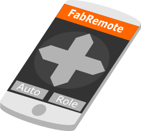
User interface for controlling the car will be implemented as an responsive www-application. Because of the limited time, similar eye-candy than it's designed in the UI mockup may not be available (Better UI is option). However, controls for pedal, brake and turning right/left will be present. Also buttons for possible extra functions may be available: a) auto is autonomous drive by using proximity sensor (and in the more demanding development phases also AI) b) role means that if speaker/neopixel lights are present, car can be turned into e.g. police car
Potential candidates for implementing mobile phone controls for the carFor design spiral will focus on creating joystick controls for the car: a) forward; b) backward; c) left; d) right. In the next spiral speed control for motors will be added, as well as, ultrasonic sensor.
I have got ideas of using different control frameworks during Fab Academy.N Node-RED could be used as one alternative for controlling car. That flow-based development tool for visual programming uses HTML5 www-pages for controlling the connected equipment. I did test this approach in my earlier Fab Academy assigments.
Another approach is Blynk that I found while exploring diferent tutorials similar to this project. Blynk is hardware acgnostic internet-of-things platform, which has also good UI components for end user clients (read: mobile phones)
Programming ESP8266It would be possible to use e.g. micropython, LUA to program ESP8266 in addition to Arduino C++ language. In this final project Arduino C++ may used to program logic of the cardboard car, because other approaches are not so familiar for me.
Depending on the UI approach (Node-RED or Blynk) respective libraries will be included into code.
5. Requirements for Integration and decoration: putting everything together
Most important thing in integration phase is to design cardboard chassis and structural frame so, that those big parts can be fitted together firmly.
Wihtout parametric design, joints and slots would be difficult to design so, that everything would fit firmly into eacher other. In this project parametric design principles will be employed at least for the design of the slots in the cassis
In additon to that, additional features for the car needs cardboard fittings. E.g. to integrate possible ultrasonic sensor, neopioxel lights etc. into cardboard chassis needs tailored hands on design in-situ (lasercutting is not possible). In the picture below, you can see sketch about possible location layout of the major components.
Some extra decorations may be done by using embroidery and vinyl cutting IF time is left at the end of the project. This is additional activity and done if time to consume.
List of materials
ESP8266 Board
Partlist

Exported from board_Laru_FIN.sch at 30.6.2020 18.25

EAGLE Version 9.5.2 Copyright (c) 1988-2019 Autodesk, Inc.

Assembly variant:

Part        Value                   Device                          Package      Library   Sheet

3.3VIN      PINHD-2X2-SMD           PINHD-2X2-SMD                   2X02SMD      fab       1
C1          10uF                    CAP_UNPOLARIZEDFAB              C1206FAB     eagle_fab 1
C2          1uF                     CAP_UNPOLARIZEDFAB              C1206FAB     eagle_fab 1
FTDIVIN     SW_SLIDE-SWITCH         SW_SLIDE-SWITCH                 AYZ0102AGRLC eagle_fab 1
IC1         ESP-12E/F               ESP-12E/F                       ESP-12E      esp-12e-f 1
JP1                                 PINHD-2X3-SMD                   2X03SMD      fab       1
JP2                                 PINHD-2X3-SMD                   2X03SMD      fab       1
PROGRAMMODE SW_SLIDE-SWITCH         SW_SLIDE-SWITCH                 AYZ0102AGRLC eagle_fab 1
R1          10k                     R1206FAB                        R1206FAB     eagle_fab 1
R2          10k                     R1206FAB                        R1206FAB     eagle_fab 1
R3          12k                     R1206FAB                        R1206FAB     eagle_fab 1
R5          0                       RES-US1206FAB                   R1206FAB     fab       1
R6          0                       RES-US1206FAB                   R1206FAB     fab       1
RESET                               SW_SWITCH_TACTILE_6MM6MM_SWITCH 6MM_SWITCH   eagle_fab 1
U$4         CONN_06_FTDI-SMD-HEADER CONN_06_FTDI-SMD-HEADER         1X06SMD      eagle_fab 1
U1          VR_REGULATOR_SOT223     VR_REGULATOR_SOT223             SOT223       eagle_fab 1
Voltage step down board
Exported from stepdown_converter.sch at 30.6.2020 18.35

EAGLE Version 9.5.2 Copyright (c) 1988-2019 Autodesk, Inc.

Assembly variant:

Part            Value          Device                     Package       Library             Sheet

0.1U5VCAP       CAP-US1206     CAP-US1206                 C1206         fab                 1
0.1UF3.3VCAP    CAP-US1206     CAP-US1206                 C1206         fab                 1
0.1UF3.3VCAPOUT CAP-US1206     CAP-US1206                 C1206         fab                 1
0.1UF5VCAP      CAP-US1206     CAP-US1206                 C1206         fab                 1
0.1UF5VCAPOUT   CAP-US1206     CAP-US1206                 C1206         fab                 1
0.1UF5VCAPOUT1  CAP-US1206     CAP-US1206                 C1206         fab                 1
3.3VCON                        CONN_03X22X3_SILK_MALE_PTH 2X3           SparkFun-Connectors 1
3.3VLED         LEDFAB1206     LEDFAB1206                 LED1206FAB    fab                 1
3.3VREG                        REGULATORSOT23             SOT23         fab                 1
3.3VREG1                       REGULATORSOT23             SOT23         fab                 1
5VCON                          CONN_03X22X3_SILK_MALE_PTH 2X3           SparkFun-Connectors 1
5VLED           LEDFAB1206     LEDFAB1206                 LED1206FAB    fab                 1
5VREG                          REGULATORSOT23             SOT23         fab                 1
6VIN                           CONN_02PTH3                1X02_LONGPADS SparkFun-Connectors 1
499POWERRES                    RES-US1206W                R1206W        fab                 1
2203.3V                        RES-US1206W                R1206W        fab                 1
4995V                          RES-US1206W                R1206W        fab                 1
>6VCON                         CONN_03X22X3_SILK_MALE_PTH 2X3           SparkFun-Connectors 1
POWERLED        LEDFAB1206     LEDFAB1206                 LED1206FAB    fab                 1
R3              0              RES-US1206FAB              R1206FAB      fab                 1
Motor controller: H-Bridge L293DD
Exported from MotorDriverLaru2020FabAcademy_VER_DD-hbridge.sch at 30.6.2020 18.41

EAGLE Version 9.5.2 Copyright (c) 1988-2019 Autodesk, Inc.

Assembly variant:

Part     Value              Device             Package    Library             Sheet

5VDC     TERM-1X02-ADAFRUIT TERM-1X02-ADAFRUIT 3.5MMTERM  fab                 1
9-12VCC  TERM-1X02-ADAFRUIT TERM-1X02-ADAFRUIT 3.5MMTERM  fab                 1
ENABLE   TERM-1X02-ADAFRUIT TERM-1X02-ADAFRUIT 3.5MMTERM  fab                 1
IC1                         REGULATORSOT23     SOT23      fab                 1
IC3      L293DD             L293DD             SO20       st-microelectronics 1
INPUTA-B TERM-1X02-ADAFRUIT TERM-1X02-ADAFRUIT 3.5MMTERM  fab                 1
INPUTCD  TERM-1X02-ADAFRUIT TERM-1X02-ADAFRUIT 3.5MMTERM  fab                 1
MOTOR1   TERM-1X02-ADAFRUIT TERM-1X02-ADAFRUIT 3.5MMTERM  fab                 1
MOTOR2   TERM-1X02-ADAFRUIT TERM-1X02-ADAFRUIT 3.5MMTERM  fab                 1
R1       220                RES-US1206W        R1206W     fab                 1
R2                          RES-US1206W        R1206W     fab                 1
R3                          RES-US1206W        R1206W     fab                 1
R4                          RES-US1206W        R1206W     fab                 1
R5                          RES-US1206W        R1206W     fab                 1
R6       1K                 RES-US1206W        R1206W     fab                 1
U$1      LEDFAB1206         LEDFAB1206         LED1206FAB fab                 1
U$2      LEDFAB1206         LEDFAB1206         LED1206FAB fab                 1
U$3      LEDFAB1206         LEDFAB1206         LED1206FAB fab                 1
U$4      LEDFAB1206         LEDFAB1206         LED1206FAB fab                 1
U$5      LEDFAB1206         LEDFAB1206         LED1206FAB fab                 1
U$6      LEDFAB1206         LEDFAB1206         LED1206FAB fab                 1
Other components used
- Polulu minimotors x 2
- Cardboard 2x A3
- 9v Battery holder
- 1x 4x1,5v battery holder
To be developed (PRICES ARE MISSING ATM)
Design and Manufacturing parts of cardboard car
Cardboard parts: Desigingin car chassis and structural frame
I started my cardboard car design by using Google to get list of concept car photos. Eventually I found sideprofile of Audi TT Black edition concept (2019) from conceptcarz.com -site.side profile of Audi TT was imported to Fusion360 and then drawn into sketch by using "fit poit spline" -tool
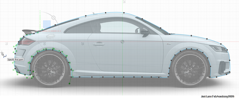
Next I sketched structural frame by using measures of side profile as starting point
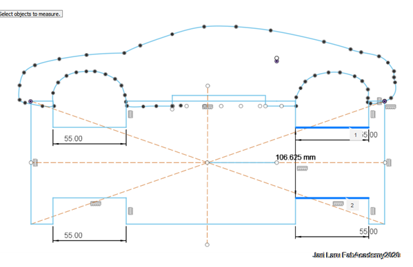
Then I did exctrude sketch of the sideprofile and created sketch of the inner profile on top of that new body
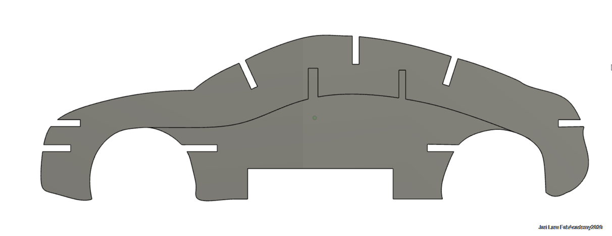
Then I did place parts into same plane in order to be turned into drawing (for pdf-export and 2D laser cutting)
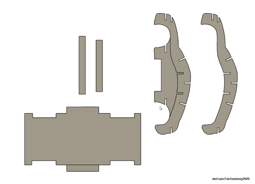
I did use "Drawing from the design" -tool in Fusion360 to get 2D files for 2D laser cutting
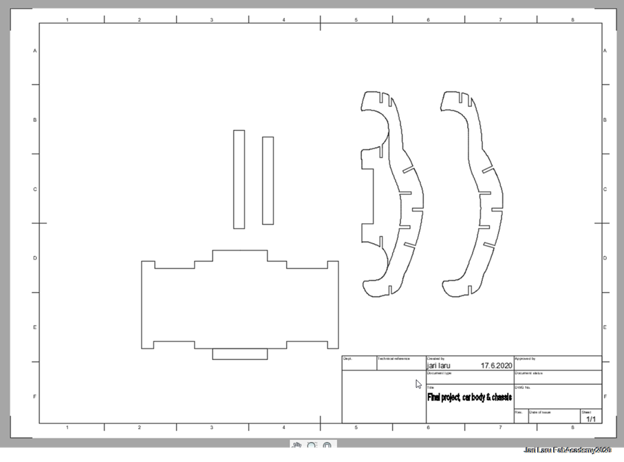
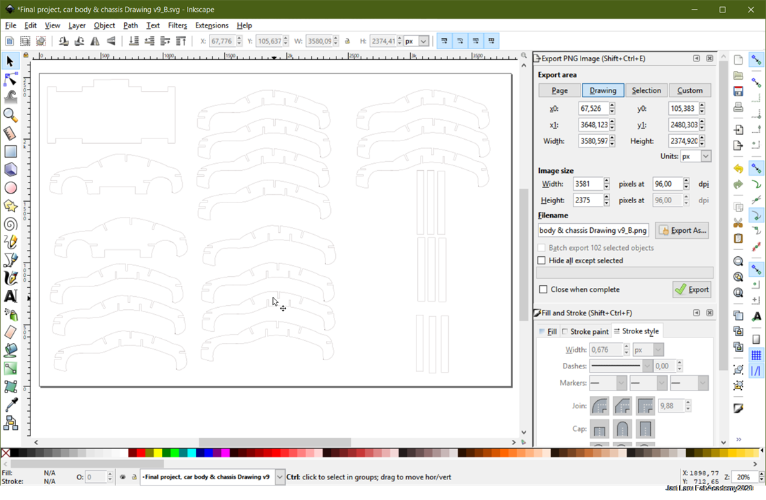
Then pdf-file was imported into Inkscape and prepared for lasercutting. Unnecessary parts were deleted and line thickness was adjusted to 0.20mm (which is appropriate for laser in our FabLab)
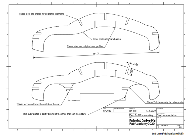
Then different parts were copied if design required that. Especially this was case for outer and inner profiles and sticks which were designed to connect profiles to each other
In total following components of car chassis were lasercut: (total width of the car 13,6cm)
- 4x carboard driver side (4x 3,78) = 15,12mm
- 27x cardboard inside = 120,96mm
- 4x cardboard passenger side (4x3,78) = 15,12mm
In addition to that structural frame and 6 longer connector sticks and 4 shorter sticks were lasercut
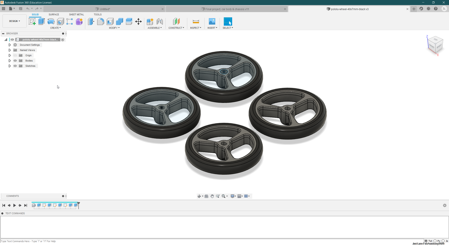
Wheels: modifying Polulu wheel desing and 3D-printing wheels
Because I did use Polulu minimotors, I naturally ended up to explore Internet to found 3D designs of wheels (Pololu Wheels 32×7mm) which has polulu compatible axel hole.
Step file for Polulu Wheel: https://www.pololu.com/product/1087/resources
However, I had to remix of wheels in order to fit front axel. I did import step file into fusion and then removed axel hole and replaced it with my own extruded circle (1,5mm) for 1mm axle
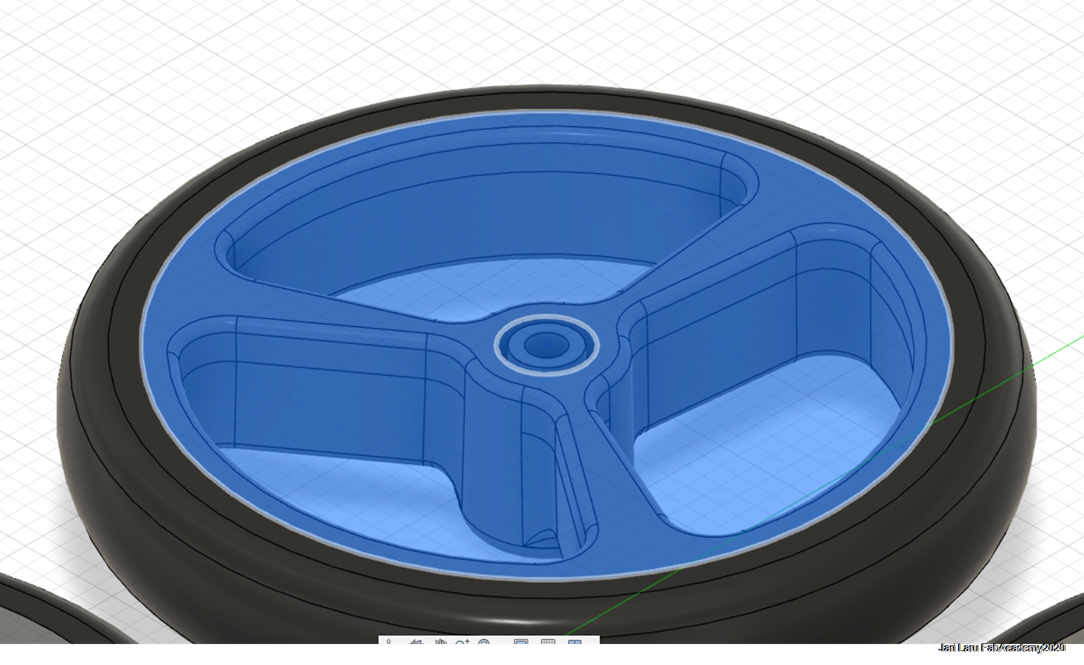
Then I did copy both Polulu -motor compatible wheel and front-axel compatible wheel so, that I had four wheels for the car and exported design as .stl-file for 3D printing
Desining and producing electronics
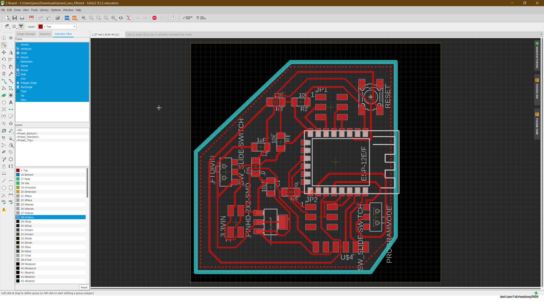
ESP8266 board
My design of ESP8266 board was derived from Neil's design of ESP-WROOM-02D board. The components used for this board include:
- ESP8266-12F Module
- 10k resistor x 2
- 12k resistor
- 1uF capacitor
- 10uF capacitor
- MOSFET SOT223 Regulator(3.3V)
- button switch (reset)
- slide switch (normal mode / program mode
- slide swithch (usb FTDI mode: regulator circuitry in use / 3,2V input from powerboard in use)
- 6-pin FTDI connector
- PINHD 2x2 connector (3,2VIN from powerboard in FTDI regulator isolation mode)
- PINHD-2X3 connector x 2 for GPIO connections
In this ESP8266 board schematics slide switch is used to choose between program and normal mode. In the program mode FTDI-cable connection can be used (after reset of the ESP8266) easily. When code is uploaded, then swich can be slided into normal mode.
This is done by pulling GPIO pins HIGH and LOW in certain order:
- Normal mode:GPIO pins GPIO0 and GPIO2 are HIGH and GPIO15 is low
- Program mode: GPIO0 is low, GPIO9 is low and GPIO2 is HIGH
So, these mode changes are done by slide switch in my design. In additon to that, I have wanted to add possibility to bypass 5v regulator in order to use 3,2Vinput from voltage step down board. So I added another slide switch to isolate it from other circuitry.
ESP8266 board design files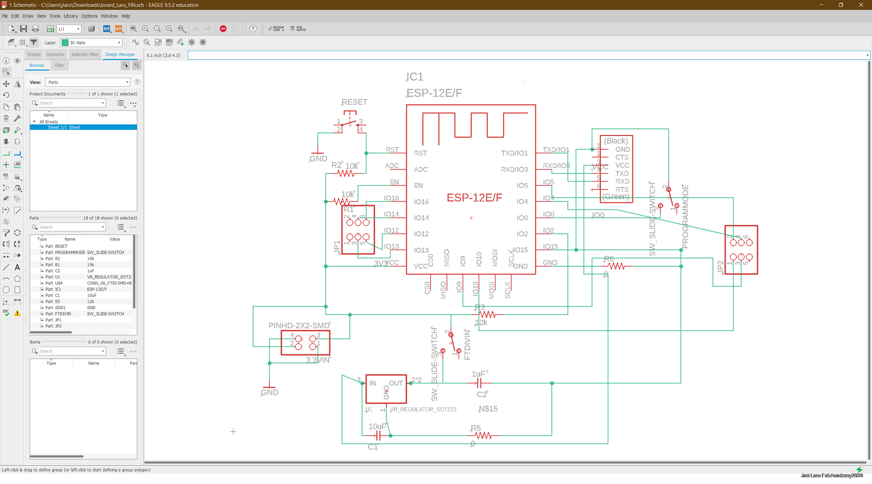
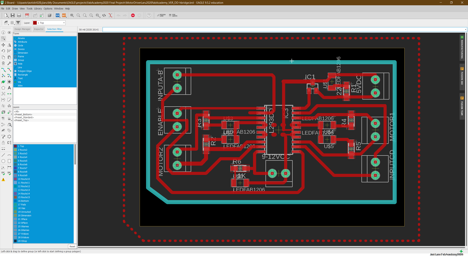
Motor controller board (H-Bridge)
H-Bridge (L293D) is very common chip for controlling DC-motors and stepper motors
You can see 4 input pins for L293D fir keft side, and pins 15 and 10 on the right side, as shown on the pin diagram below. Left input pins will regulate the rotation of motor connected across left side and right input for motor on the right hand side. The motors are rotated on the basis of the inputs provided across the input pins as LOGIC 0 or LOGIC 1. In simple you need to provide Logic 0 or 1 across the input pins for rotating the motor.
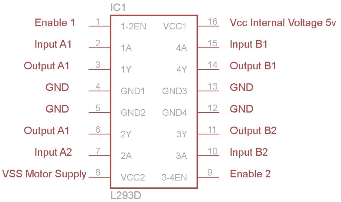
Lets consider a Motor connected on left side output pins (pin 3,6). For rotating the motor in clockwise direction the input pins has to be provided with Logic 1 and Logic 0.
Pin 2 = Logic 1 and Pin 7 = Logic 0 | Clockwise Direction
Pin 2 = Logic 0 and Pin 7 = Logic 1 | Anticlockwise Direction
Pin 2 = Logic 0 and Pin 7 = Logic 0 | Idle [No rotation] [Hi-Impedance state]
Pin 2 = Logic 1 and Pin 7 = Logic 1 | Idle [No rotation]
In a very similar way the motor can also operate across input pin 15,10 for motor on the right hand side
In my design I used LEDs for debugging signals (power inputs and motor outputs
Schematics and board in Eagle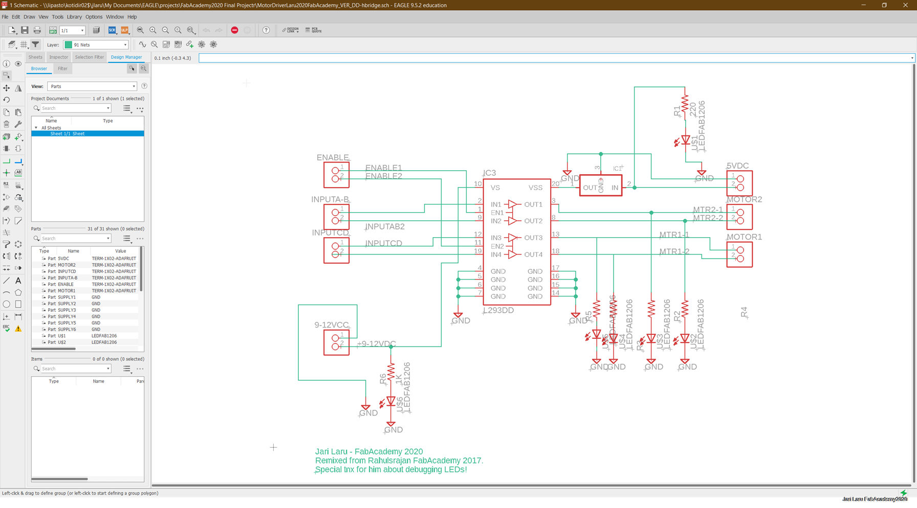
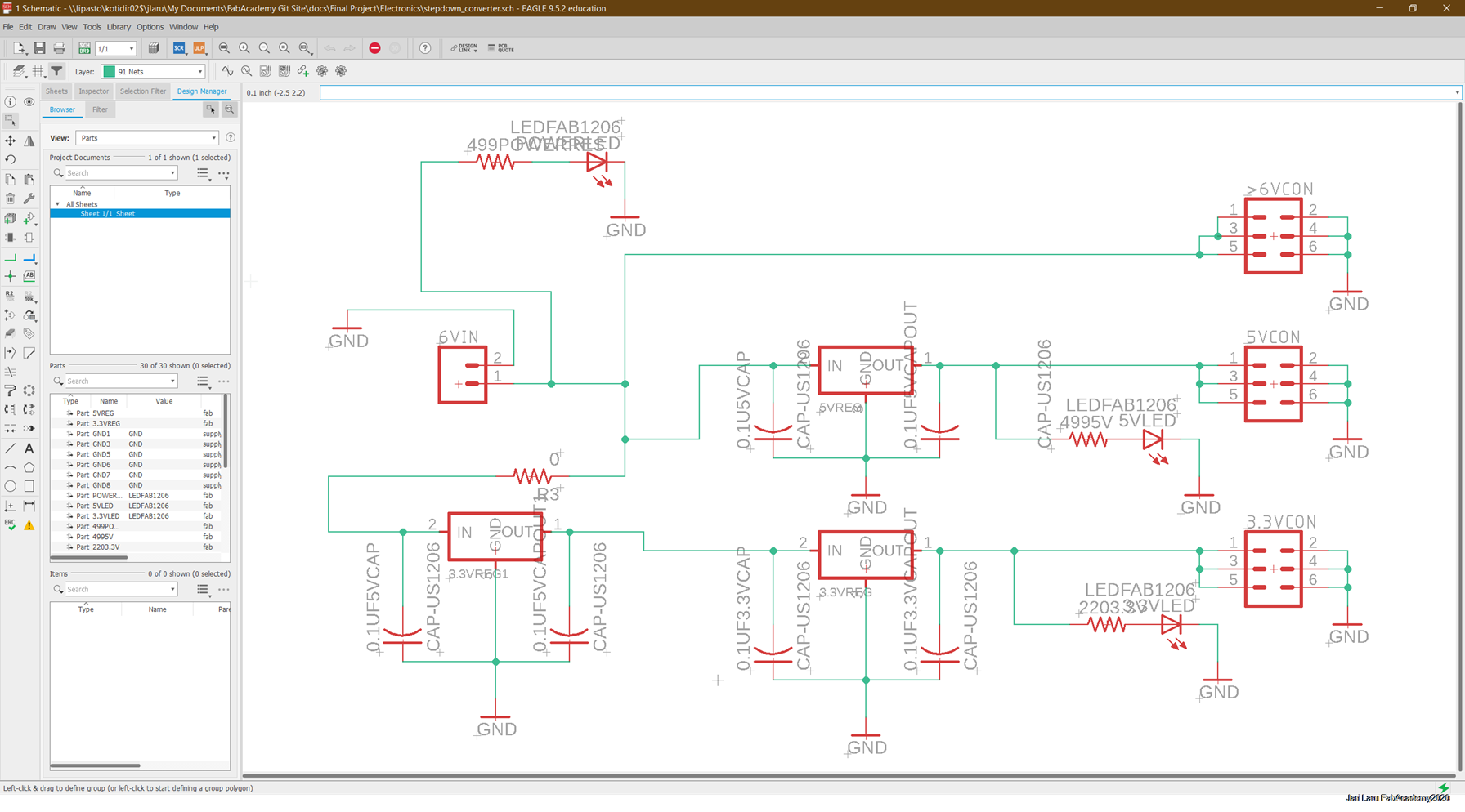
Voltage step down board
Voltage step down circuitry is needed because different components in the cardboard car consume different voltage levels:
- 3,2V ESP8266 VIN
- 5V L293D H-Bridge Motor controller Vcc (internal voltage 5v)
- 5V Servo (may be used in the second design spiral)
- 5V Ultrasonic sensor (may be used in the second design spiral)
- 7V or higher Polulu minimonotors
So, circuit was designed so, that highest voltage went straight trough to output pins. 5V voltage had one regulator and 3,2V voltage had one 5V regulator and one 3V regulator.
I used LEDs for debugging, to see that all connections work
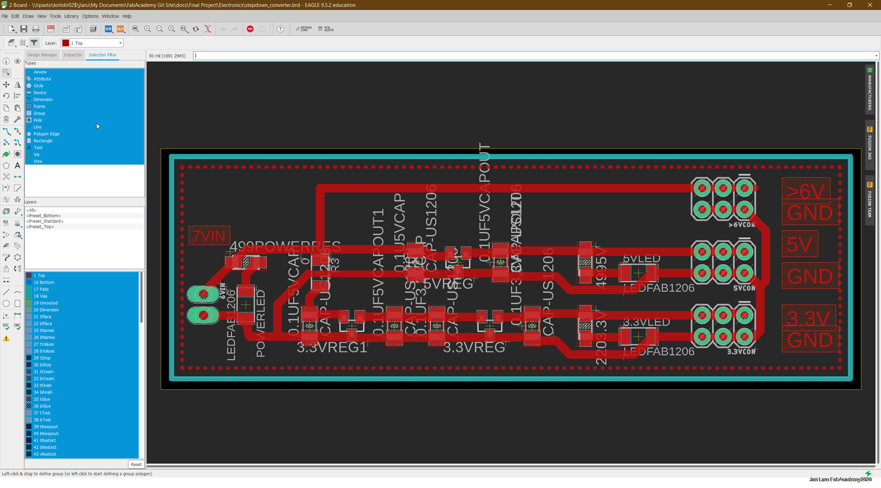
Milling and soldering electronics
png-files were exported from the Eagle and then were used to create rml-files were done by using http://mods.cba.mit.edu/ -service
Then .rml-files were opened in user milling machine SRM-20 and board were milled
Blynk Joystic controller as input and Polulu minimotors as output
OUTPUT: Polulu minimotors were used for driving and steering
Polulu minimotors were used for steering and driving in the context of this project
Motor controller board (L293DD H-Bridge) is used to change direction of the motors. In this project (and in many others) this functionality is used also for steering.
So, when first motor runs forward and second motor runs backwards it will turn the car. Servo control for steering would be more accurate, but I did end up to use H-Bridge also for steering to consume time
I have tested servo steering code with separate servo, but didn't have time to integrate it into vehicle now.
Because I did drop servo steering from the project, front wheels are just connected straight axel which goes trought the corrugated cardboard
INPUT: Blynk joystick widget
Most interesting this in the context of FabAcademy was the opportunity to try different user interface frameworks. I have used Node-RED and Blynk and eyed also other alternatives
Because our group used Node-Red to control our cardboard robot in the machine building week, I chose alternative to this task. That alternative is Blynk.
I also like Blynk's idea of using virtual pins for communication between the software client (mobile device) and hardware client (ESP8266 in my project context).
One thing was that I didn't like so much: when you start to use Blynk, it automatically connects your hardware and software clients trough the cloud. Cloud version of the Blynk is freemium service, it has concept called "energy", which decreases when you add widgets to user interface.
However, it can be bypassed by installing Blynk Server (java-based application) to your computer. I did use Raspberry Pi for that purpose.
Configuring software client (mobile phone client a.k.a remote controller of the car)
When you take Blynk into use (trough mobile app) you need to create account. When account is created, you can start new project. Project is the "thing" which is used for creating controls (widgets) and connections to code (e.g. Arduino C++)
When you create project, secret key will be generated and sent to your email. Key is project spesific and needs to be used in Arduino IDE to configure Blynk
Blynk application (mobile app) has widget area where you can add differet views and controls. Widgets can be added by clicking + (top right corner)
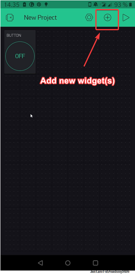
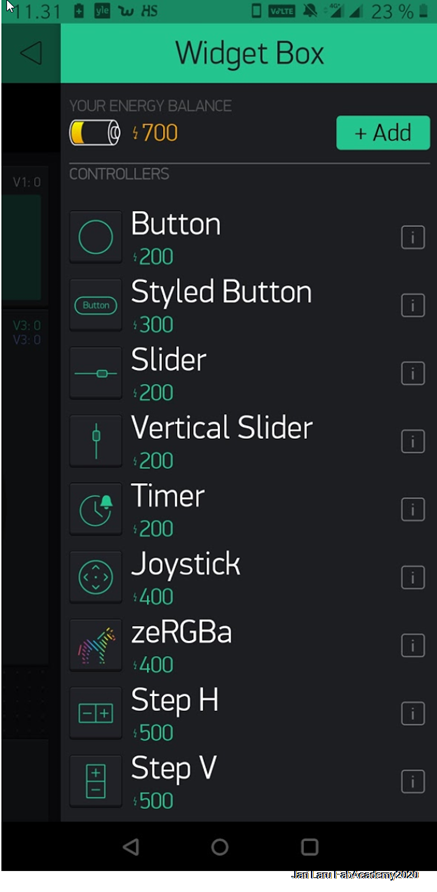
Widget box has a collection of widgets available. However, when you are connected via cloud (like in this case) only limited amount of the widgets are available (or actually you have limited amount of the virtual currency called energy and you need to buy it if you run out of it)
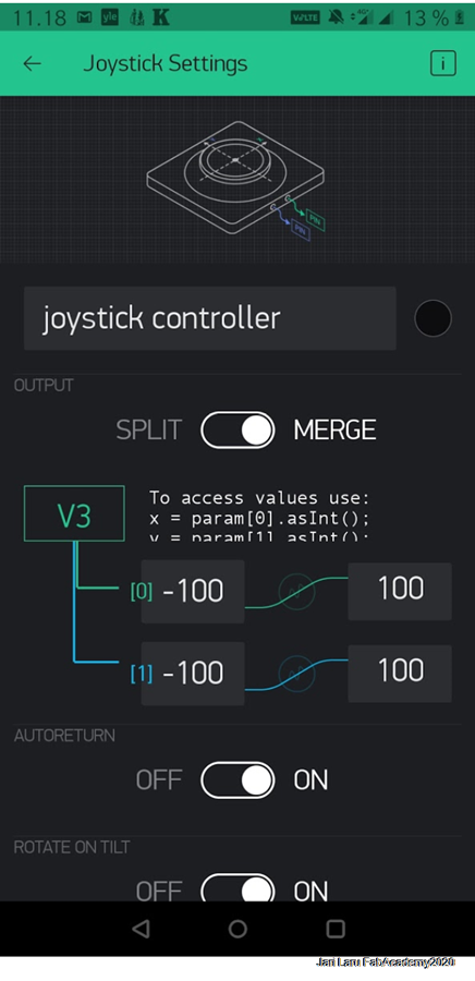
Each widget has configuration properties. For example, widget used for car controls, joystick, has a dialog where you can split or merge virtual pins. In the picture only one virtual pin is used and values will be parsed in the ESP2866 end by using code. If you choose split, it does consume bandwith between Blynk clients and server and it's not recommended.
In my case X and Y axis has minimum values set to -100 and maximum values set to 100
Other settings, like autoreturn and rotate on tilt are more or less additional, setting up virtual pin its only thing need to be configured.
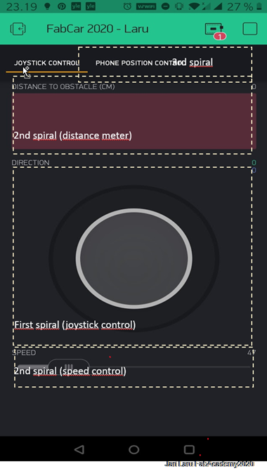
In this picture you can see different widgets in the use:
- Tabs widget: joystick control (in this projec, first design spiral) / phone position control (3rd development spiral)
- Horizontal display widget (Level H) to show distance to objects (2nd design spiral)
- Slider-widget: used in the next design spiral for speed control of motors (PWM pulse) (2nd design spiral)
ESP2866 code
/********************************************************************
* This code needs Blynk app to be installed into phone              *
*                                                                   *
* Used Blynk widgets are: joystick for controls and Horizontal      *
* value display                                                     *
*                                                                   *
*  CC-BY-SA Jari Laru, Fab Academy 2020                             *
 ********************************************************************/


/* ESP2866 and Blynk Libraries are included */
#define BLYNK_PRINT Serial /* This library adds blynk spesific info to serial communication between Arduino IDE and board, can be removed after testing */
// #include  Servo Library is disabled, because I did simplify implementation and removed servo controlled precision steering.
#include  /* ESP wifi Library */
#include  /* Blynk Library */

/* Pins for ultrasonic sensors are defined here */
#define TRIGGERPIN 1
#define ECHOPIN  3

/*  L293D motor enable pins are defined here */
int rightMotorEN = 14 ; /* GPIO14 -> Motor-A Enable  */
int leftMotorEN =  4 ;  /* GPIO12 -> Motor-B Enable */

/* L293D motor control pins are defined here */
int leftMotorForward = 13;     /* GPIO5 -> IN3   */
int rightMotorForward = 16;   /* GPIO4 -> IN1  */
int leftMotorBackward = 5;    /* GPIO10  -> IN4   */
int rightMotorBackward = 12;  /* GPIO9 -> IN2  */


/* Auth token for Blynk */
char auth[] = "SECRET-YOY-WILL-GET-THIS-FROM-BLYNK-PROJECT";

/* Local wifi network settings for Blynk. HOX! If you are running own server, then server and this client needs be in same SSID */
char ssid[] = "SSID";
char pass[] = "PASSWORD";

/* Local Blynk Server adress. It can be run also by using cloud service, but then amount free UX components is limited.
 *  Own server has unlimited access.  In my case Rasperry Pi is server */

char server[] = "192.168.100.10";


// Reading ultrasonic sensor and sending readings to Blynk horizontal bar

BLYNK_READ(9) {

  long duration, distance;
  digitalWrite(TRIGGERPIN, LOW);
  delayMicroseconds(3);

  digitalWrite(TRIGGERPIN, HIGH);
  delayMicroseconds(12);

  digitalWrite(TRIGGERPIN, LOW);
  duration = pulseIn(ECHOPIN, HIGH);
  distance = (duration/2) / 29.1;
  Serial.print(distance);
  Serial.println("Cm");

  Blynk.virtualWrite(9,distance);
}

// Handling Joystick data from Blynk and controlling left and right motors based on that
BLYNK_WRITE(V3){
int x = param[0].asInt();
int y = param[1].asInt();

 // Do something with x and y
  Serial.print("X = ");
  Serial.print(x);
  Serial.print("; Y = ");
  Serial.println(y);

 if(y == 100)
 GoForward();  //Forward

 else if(y == -100)
 GoBackward(); //Backward

 else if(x > 100)
 TurnRight(); // Right turn

 else if(x < -100)  // Left turn
TurnLeft();

 else if (x == 0 && y == 0)
 Stop();
}


// GO FORWARD //
void  GoForward(void)
{
  Serial.println();
  Serial.print("Go to forward");
  analogWrite(leftMotorEN,255);
  analogWrite(rightMotorEN,255);
  digitalWrite(leftMotorForward,HIGH);
  digitalWrite(rightMotorForward,HIGH);
  digitalWrite(leftMotorBackward,LOW);
  digitalWrite(rightMotorBackward,LOW);
}

// Go backward //
void GoBackward(void)
{
  Serial.println();
  Serial.print("Go to backward");
  analogWrite(leftMotorEN,255);
  analogWrite(rightMotorEN,255);
  digitalWrite(leftMotorBackward,HIGH);
  digitalWrite(rightMotorBackward,HIGH);
  digitalWrite(leftMotorForward,LOW);
  digitalWrite(rightMotorForward,LOW);
}

// TURN LEFT //
void TurnLeft(void)
{
   Serial.println();
   Serial.print("turn to left");
  analogWrite(leftMotorEN,255);
  analogWrite(rightMotorEN,255);
  digitalWrite(leftMotorForward,LOW);
  digitalWrite(rightMotorForward,HIGH);
  digitalWrite(rightMotorBackward,LOW);
  digitalWrite(leftMotorBackward,HIGH);
}

// TURN RIGHT //
void TurnRight(void)
{
  Serial.println();
  Serial.print("turn to right");
  analogWrite(leftMotorEN,255);
  analogWrite(rightMotorEN,255);
  digitalWrite(leftMotorForward,HIGH);
  digitalWrite(rightMotorForward,LOW);
  digitalWrite(rightMotorBackward,HIGH);
  digitalWrite(leftMotorBackward,LOW);
}

// STOP //
void Stop(void)
{
  Serial.println();
  Serial.print("Stopped");
  analogWrite(leftMotorEN,0);
  analogWrite(rightMotorEN,0);
  digitalWrite(leftMotorForward,LOW);
  digitalWrite(leftMotorBackward,LOW);
  digitalWrite(rightMotorForward,LOW);
  digitalWrite(rightMotorBackward,LOW);
}


void setup() {

//********** CHANGE PIN FUNCTION  TO GPIO **********
//GPIO 1 (TX) swap the pin to a GPIO.
pinMode(1, FUNCTION_3);
//GPIO 3 (RX) swap the pin to a GPIO.
pinMode(3, FUNCTION_3);
//**************************************************


  /* motor control pins are here initialized as outputs */
  pinMode(leftMotorForward, OUTPUT);
  pinMode(rightMotorForward, OUTPUT);
  pinMode(leftMotorBackward, OUTPUT);
  pinMode(rightMotorBackward, OUTPUT);

  /* motor enable pins are initialized here as outputs */
  pinMode(leftMotorEN, OUTPUT);
  pinMode(rightMotorEN, OUTPUT);

/* Ultrasonic sensor is initialized here: trigger as output and echo as input */
  pinMode(TRIGGERPIN, OUTPUT);
pinMode(ECHOPIN, INPUT);

/* Debug console is activated */
Serial.begin(115200); //debug console

/* Connection to Blynk server  is initialized */
// I did enable my local server connection, because I did work outside the home
Blynk.begin(auth, ssid, pass, server, 8080);

// I did disable Blynk cloud connection
//  Blynk.begin(auth, ssid, pass);
}


void loop() {
  /* run Blynk */

Blynk.run();

}
Integration
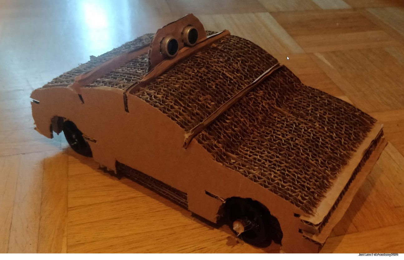
In the integration phase I did connect all cardboard parts together. Slots done by using parametric design fitted very well together with cardboard "bars" which were lasercut to connect pieces together
Dissemination plan and licencing
Dissemination plan
The product of the final project is not going to be commercial I will utilize this project in the context of Alvin AI robot co-design context. Our aim is to design and create affordable robotics for K-12 contexts. My own aim is also to conduct academic research in tis context.
The parts of this project which are usable in my next steps are related to cardboard design and idea of remote controlling/electronics. I will use NodeMCU to replace self-designed and milled PCBs in oder to avoid complexity and reduce time needed for the process
License
Since the idea of my final project is to design cardboard car for K-12 education context, I want to let others use my work for non-commercial purposes. Hence I’m choosing Creative Commons with ShareAlike and NonCommercial licenses.
- Creative Commons license: one of several public copyright licenses that enable the free distribution of an otherwise copyrighted work. A CC license is used when an author wants to give other people the right to share, use, and build upon a work that the author have created.
- ShareAlike: If you remix, transform, or build upon the material, you must distribute your contributions under the same license as the original
- NonCommercial: You may not use the material for commercial purposes
Files and documents
- Cardboard car design files:
- [FUSION360] Cardboard chassis and structural frame and other components (Fusion360 F3D-file):docs/Final Project/Car 2D and 3D/Final project, car body & chassis v11.f3d
- [FUSION360] Minor steering componens and wheels locking components (Fusion 360 PDF-file , Drawing from Design) [for lasercutting]: docs/Final Project/Car 2D and 3D/Final project, car body & chassis Drawing v9.pdf
- [FUSION360] Cardboard chassis and structural frame and other components (Fusion 360 PDF-file , Drawing from Design) [for lasercutting]: docs/Final Project/Car 2D and 3D/Final project, car body & chassis Drawing v9.pdf
- [FUSION360] Minor steering componens and wheels locking components (Fusion 360 PDF-file , Drawing from Design) [for lasercutting]: docs/Final Project/Car 2D and 3D/Final project, car body & chassis Drawing v9.pdf
- [INKSCAPE] Inkscape Design Document where Fusion360 pdf was post-edited:docs/Final Project/Car 2D and 3D/Final project, car body & chassis Drawing v9.svg (Inkscape SVG)
- Wheels design:
- [FUSION360] Polulu wheels remixed):Polulu Wheels remixed: rear wheels with polulu axel hole and front wheels with 1,5mm hole
- [STL-file for 3D-print]File for 3D-print):File for 3D-printing
- Electronics design and production
- [Eagle] ESP8266 schema: docs/Final Project/Electronics/board_Laru_FIN.sch
- [Eagle] ESP8266 board: docs/Final Project/Electronics/board_Laru_FIN.brd
- [Eagle] ESP8266 partlist: docs/Final Project/Electronics/ESP8266parts
- [Eagle] L293DD motor controller schema: docs/Final Project/Electronics/MotorDriverLaru2020FabAcademy_VER_DD-hbridge.sch
- [Eagle] L293DD motor controller board: docs/Final Project/Electronics/board_Laru_FIN.brd
- [Eagle] L293DD motor controller partlist: docs/Final Project/Electronics/motorcontroller_parts
- [Eagle] Voltage step down board schema: docs/Final Project/Electronics/stepdown_converter.sch
- [Eagle] Voltage step down board board: docs/Final Project/Electronics/stepdown_converter.brd
- [Eagle] Voltage step down board partlist: docs/Final Project/Electronics/motorcontroller_parts
- Programs
- [Arduino IDE] ESP8266 code (Arduino C++):docs/Final Project/Code/FabCar2020_LaruFIN_b/FabCar2020_LaruFIN_b.ino
Page menu
under development