Output Devices
Tasks for this week:
- Add an output device to a microcontroller board you've designed, and program it to do something.
Part 1- Working with Liquid Crystal Display
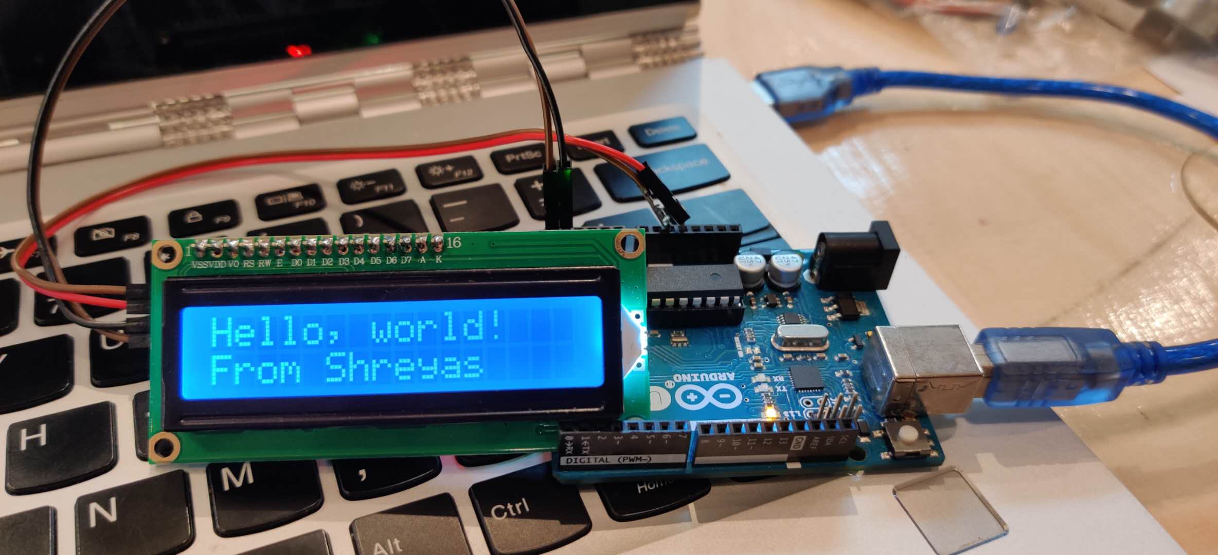
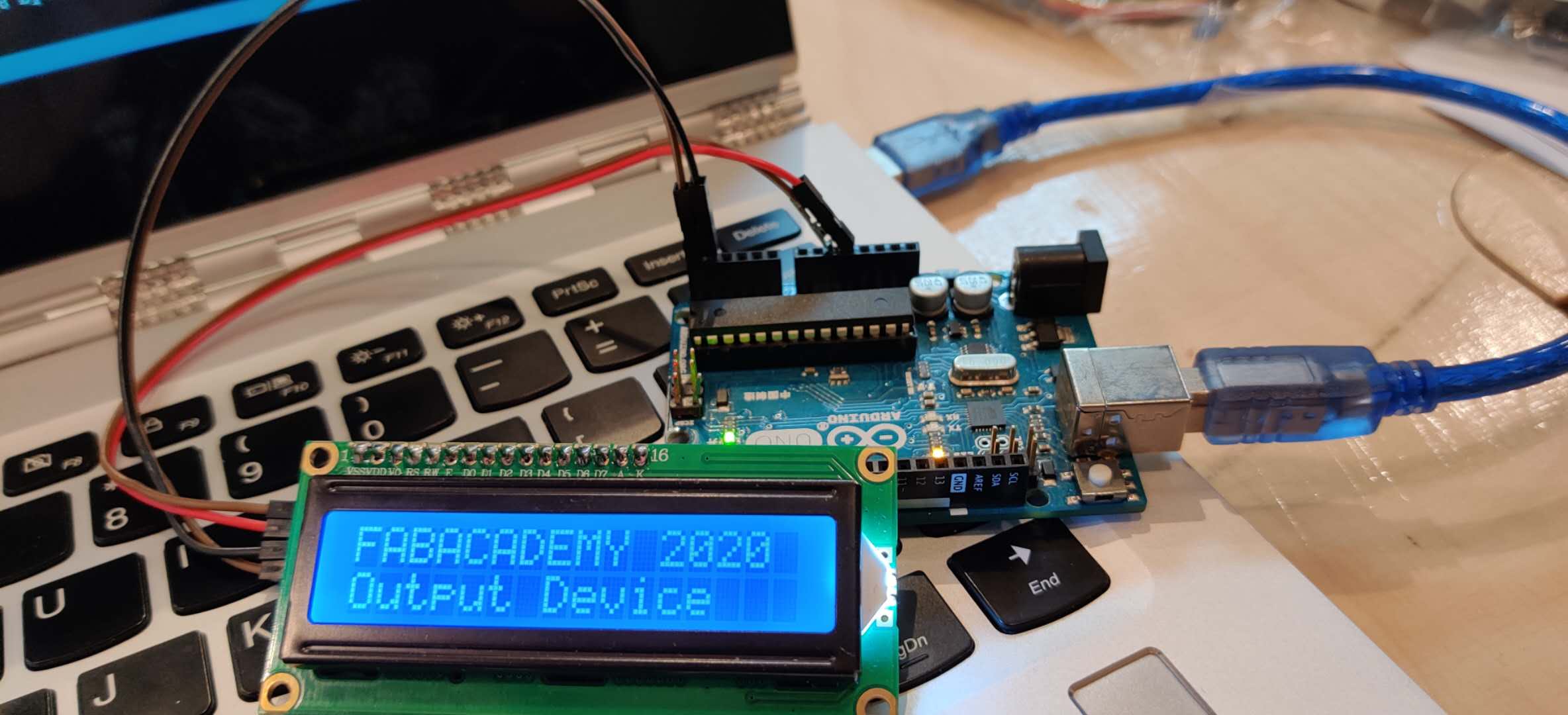
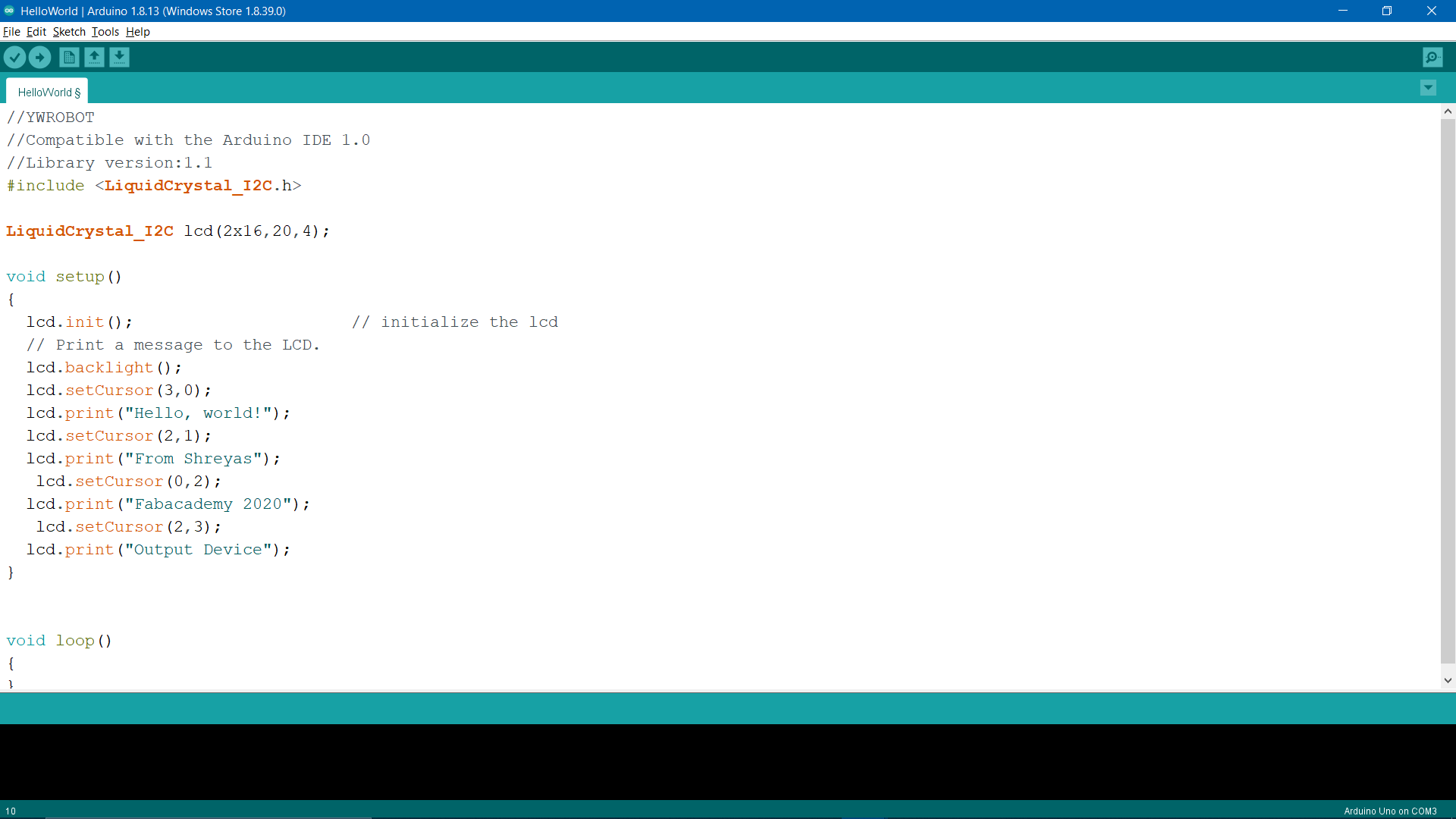
For this week, I decided to use a LCD display, as it is one of the most common output device utilized in many applications. I used a Hello-World LCD custom example, and modified the code to make it fit on a 16X2 LCD. This was a very simple exercise, and there is no notable things to mention, except that in some cases, if you can't see anything on the LCD screen, then you can adjust the brightness and contrast of the display using a potentiometer at the back of the display.
One cool thing I managed to do was create a Pacman animation. I used code presented by a past year student, and modified the text. The way this animation works is that the the special character is printed, then replaces itself, and the content, on the next square. At a fast rate, it appears like the character is moving forward. Overall, it was a pretty neat exercise.
Part 2- Working with Stepper Motors
I really wanted to work with stepper motors this week, as I'll be using 6 of them in my final project. I followed a tutorial by the YouTube channel 'How To Mechatronics', and I followed 2 others and double-checked with them, but I could not get the stepper motors to work at all. One thing I noticed early in the debugging process was that I was missing a capacitor between the power supply and the driver. After adding this, however, the board still didn't work. I checked with a new motor, and still couldn't make the motor work. I didn't make significant process in debugging, therefore I don't have much to document. I will update this page soon.
Update! So, the stepper motors finally worked. I was sure that my connections were correct, and I was right. The problem was with the driver. I don't know what exactly was wrong with the driver, just that replacing the component and re-uploading the code worked.
One additional fun thing I managed to do this week was play the Mario theme song on the stepper motor. I found the code on GitHub, and uploaded it to the arduino board (attached at the end of the page). Each note is played by a certain stepping motion of the motor. This is the result:

Update 2- (17/7/2020) This is me updating the documentation after completing the final project. I will firstly briefly talk about how stepper motors work. Stepper motors are DC motors that move in discrete steps, otherwise understood as specific angles. They have multiple coils that are organized in groups called "phases". By energizing each phase in sequence, the motor will rotate, one step at a time. With a computer controlled stepping you can achieve very precise positioning and/or speed control, which is what the stepper motor drivers are for. In terms of how the motor actually rotates:
1. The right electromagnet is energized and becomes a north pole (red) and the left electromagnet becomes a south pole (blue). This pulls the rotor around by one step so a blue tooth on the rotor snaps toward the right electromagnet and a red tooth snaps toward the left electromagnet.
2. Now the bottom electromagnet becomes a north pole, the top magnet becomes a south pole, and the two horizontal magnets are switched off. Again, the teeth of the rotor are pulled around by one step.
3. The vertical magnets are now switched off and the horizontal magnets are switched on again, but with the opposite polarity (pattern of magnetism) that they had before. The teeth of the rotor advance by one more step.
4. Finally, the vertical magnets are switched on again, in the opposite polarity to before, and the horizontal magnets are switched off. The rotor mores around one more step. The whole cycle then repeats.
You can find additional documentation about stepper motors, drivers, and making my own 6 driver shield <here.
Update:
Recently, I managed to get my version of an ATMega328 board (called Rupino). Therefore, I repeated the LED Output Devices exercise to complete this week's assignment. This time, I decided to use the SerialDisplay example from the LiquidCrystal_I2C library.
Error:
The connections on my Rupino were correct, and I could successfully upload the code onto it. However, all the LCD would show was blocks. I tried adjusting the potentiometer, but it would only change the brightness, not the actual display output. I did some research, and figured out that the address of the LCD might be different. The most common ones are 0x27 and 0x3F. So, in the code, I changed it to 0x3F, uploaded it, and it worked.
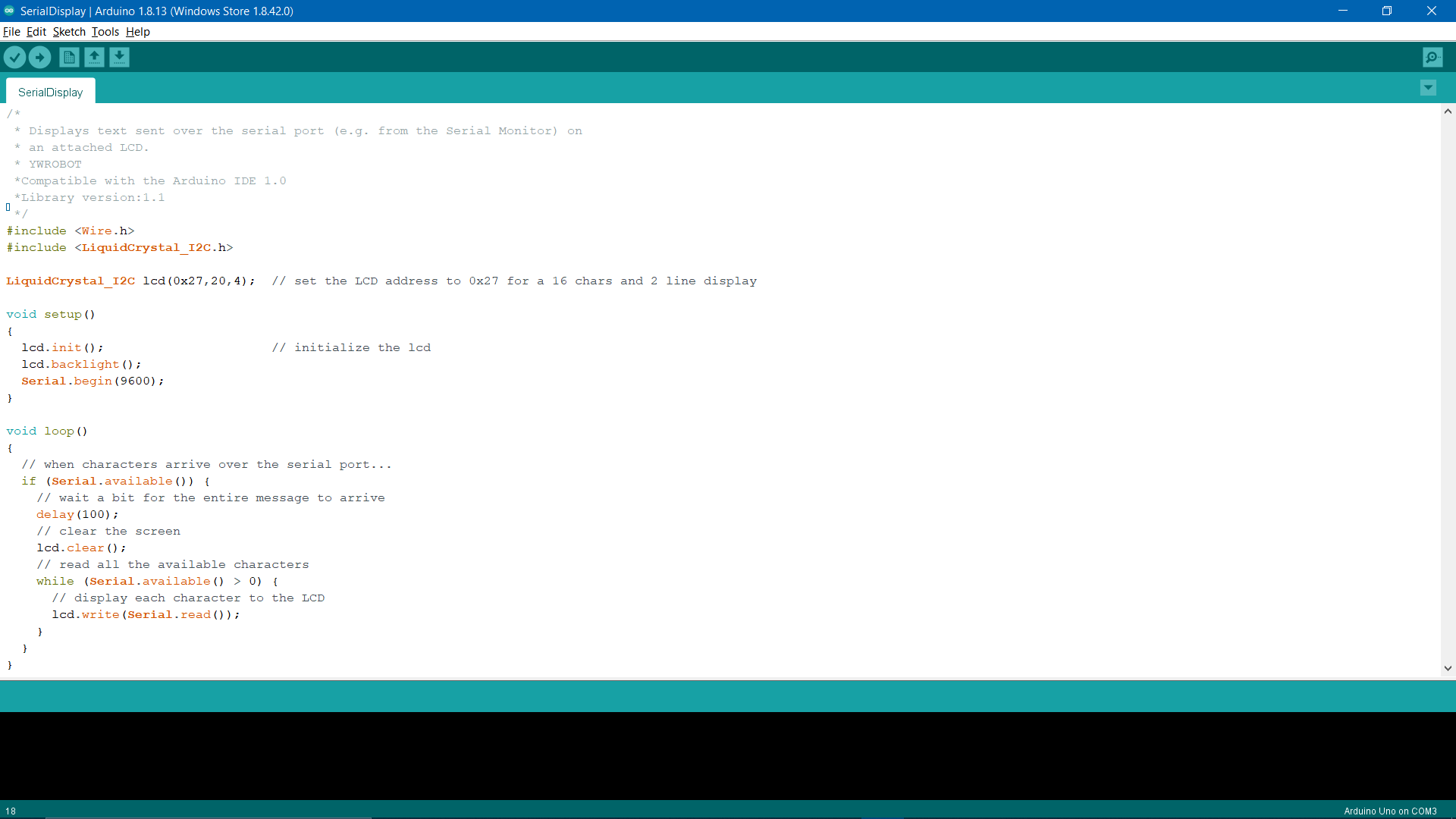
I then opened the serial monitor, and the message I typed would display on the LCD. Since the code consists of lcd.clear(), it would erase the previous message and print the new one, regardless of the position of the characters on the LCD. Here's the demo:
Click here to download the LCD Message Arduino Code
Click here to download the LCD Serial Message Arduino Code
Click here to download the Super Mario Stepper Motor Arduino Code