Networking and Communications
Tasks for this week:
- Group- Send a message between two projects.
- Design, build, and connect wired or wireless node(s) with network or bus addresses.
Part 1- Group Assignment
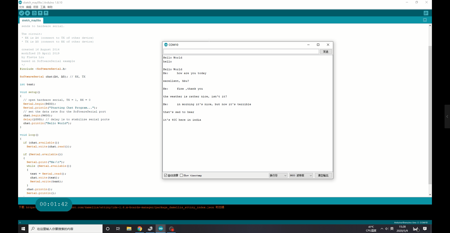
For the group assignment, we uploaded codes that would enable two boards to communicate in a chat conversation on the serial monitor. Here is the link to the group assignment documentation.
Part 2- I2C Protocol
The Inter-Integrated Circuit (I2C) Protocol is a protocol intended to allow multiple "slave" digital integrated circuits ("chips") to communicate with one or more "master" chips. Like the Serial Peripheral Interface (SPI), it is only intended for short distance communications within a single device. It only requires two signal wires to exchange information.
The I2C communication protocol works by setting up a MASTER and a SLAVE(S) connected by two signal wires for communication, this is SCL (Serial Clock) and Serial Data (SDA) connections. Once you set up who is the master and who is the slave you have to upload a code into each of them to start the I2C communication. I used Arduino IDE to upload the codes into the master board and the slaves, as both the master and the slave has their own code. The code I used is master-writer and slave-reciever from the Wire example library in Arduino IDE.
Slave Reciever#include Wire.h
void setup() {
Wire.begin(8); // join i2c bus with address #8
Wire.onReceive(receiveEvent); // register event
Serial.begin(9600); // start serial for output
}
void loop() {
delay(100);
}
// function that executes whenever data is received from master
// this function is registered as an event, see setup()
void receiveEvent(int howMany) {
while (1 < Wire.available()) { // loop through all but the last
char c = Wire.read(); // receive byte as a character
Serial.print(c); // print the character
}
int x = Wire.read(); // receive byte as an integer
Serial.println(x); // print the integer
}
Master Writer
#include Wire.h
void setup() {
Wire.begin(); // join i2c bus (address optional for master)
}
byte x = 0;
void loop() {
Wire.beginTransmission(8); // transmit to device #8
Wire.write("x is "); // sends five bytes
Wire.write(x); // sends one byte
Wire.endTransmission(); // stop transmitting
x++;
delay(500);
}
The following section will outline certain clarifications regarding this assignment.
- 1. The master code has a part that is making numbers, start with 0 and add 1 at every loop, and in the comments of the code above, you can see that the Wire.write() command is used to transmit 1 byte to the recieving device. And since it is a loop, after 500 millisecond intervals, it sends the next byte. Essentially, that byte is +1 to the current count.
- 2. This code only displays the numbers on the slave, the numbers are the messages (bytes) that one board sends to the other. There is no storage of the numbers, and each byte sent is replaced by the subsequent transmission.
- 3. Through the serial communication, the slave board is addressed. The slave board has a name and the master is sending messages to that board specifically, and theoretically you could have more slaves with other names and the master board could choose to send a specific message to a specific board. However, in this case, there is only one slave board being addressed.
Since I still don't have a working arduino, I decided to use the arduino on a breadboard, as it can be considered a board that I have made. I uploaded the master code onto my board, then uploaded the slave code on a standard Arduino Uno. I opened the serial monitor, and here I saw the first error! of this assignment. For some reason, I could not see anything being registered on the serial monitor. The troubleshooting I attempted involving checking the connections of the wires on my arduino on a breadboard (some connections might be loose from transportation), as well as uploading the other code and therefore swapping the master and the slave board. In the end, I finally realized the problem. The chip layout I was looking at for the SDA and SCL connections on the arduino on a breadboard were that of a ATMega16 chip, whereas the SDA and SDL pins on the ATMega328 pin were positioned differently. After swapping the pins, the code was working.
Update:
Recently, I managed to get my version of an ATMega328 board (called Rupino). Therefore, I repeated the assignment exercise described above. I connected the Rupino to the commercial Arduino Uno's GND, SDA and SDL. I uploaded the slave-receiver code onto Rupino, and the master-writer code onto the Uno. Then, I opened the serial monitor, and the communication was evident:
Note:
This week definitely has been a challenge for me. After completing the assignment, I still cannot confidently claim that I have a solid understanding about networking and communications. Nevertheless, I have learnt a lot of new abbreviations and protocols, and this week involved some extremely important concept to understand in the electronics world.