Molding and Casting
Tasks for this week:
- Group- Review the safety datasheets for each of your molding and casting materials, then make and compare test casts with each of them.
- Design a mold around the stock and tooling that you'll be using, mill it (rough cut + (at least) three-axis finish cut), and use it to cast parts.
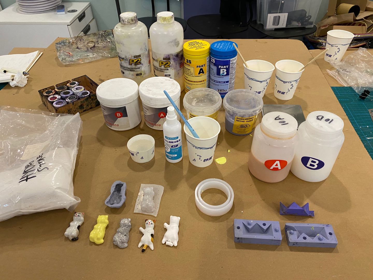
Part 1- Group Assignment
We have completed the group assignment, the documentation will be linked soon.
Part 2- Individual Assignment
The task of this week was to design a 3D mold using the stock material provided (modelling wax), mill the design with the CNC machine, produce a mold with silicone rubber, then use it to cast parts. Initially, I had no idea what exactly I wanted to make for this week. A common theme was making jewellery and keychains. After the local class, my instructor suggested to make the design simple, such as a one-part mold, to save time, as this week involves processes that take a long time.
I decided that I wanted to make a keychain or something similar, as these only require a one-part mold. I realized that my dog will be turning 2 years old in a week, so I decided I wanted to make a gift for him. I eventually decided to make a dog name tag for him, which can be attached to his collar.
I really wanted to produce a really well-finished product at the end of this week, so I decided I will be casting with metal this week. Our lab had the Bismuth alloy, which is great for casting into silicone rubber, as it only has 100C melting point.
I learnt Solidworks this week. You can't let that 1-year membership go to waste, can you? ;)
After learning the basic tools, which was a simple process because I have some experience with CAD softwares now, I followed this tutorial that shows how to make parts from a vector image. The design I chose for this was a really cool, almost abstract art of a wolf. I take great pride when people compare my dog to a 'wolf dog', or 'lang gou' in chinese. Moreover, there were more examples of vector art when searching with the search term 'wolf' rather than 'german shepherd'.
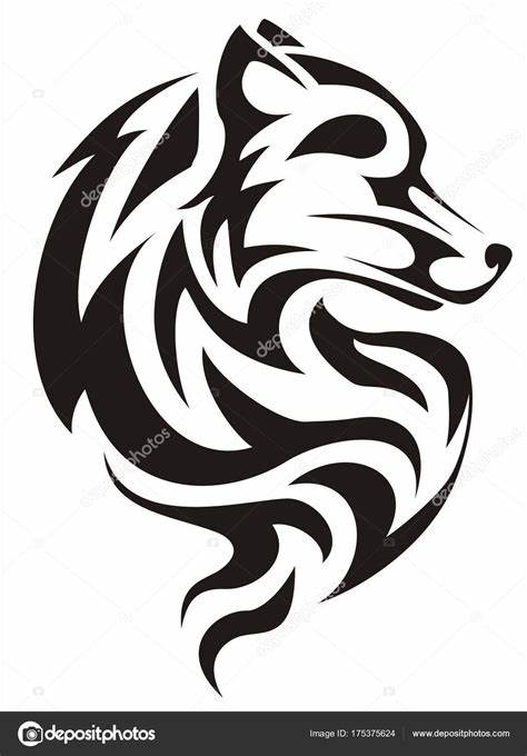
I traced the areas using the Spline tool, then, I extruded the traced areas, and chamfered the edges.
Another image was used as the main outline for the entire nameplate, which also has the outline shape of a german shepherd.
This is what it finally looked like in Solidworks.
The model was exported as .SLDPRT file, then imported into Fusion 360. I decided to switch the software for designing the mold because I am currently more familiar with Fusion 360. After importing the model, I captured the design history, then I modelled the 142X92X36 cm wax block in another file. I negatively extruded a suitable area, leaving a 1 cm margin for the wall from both edges. I then inserted the model into the wax block model, decreased the opacity of the main body to carefully position the model inside the cavity of the wax mold. Tip -The only modification I had to make to the master design was to lower the cavity to ensure a minimum of 5cm cavity from the highest point on the design and the top surface of the wax block. I did not make 95 degree angled walls, as this was a shallow, one-part mold, and the silicone would be flexible enough to remove. However, this was sort of an issue later on. The final result looked like this:
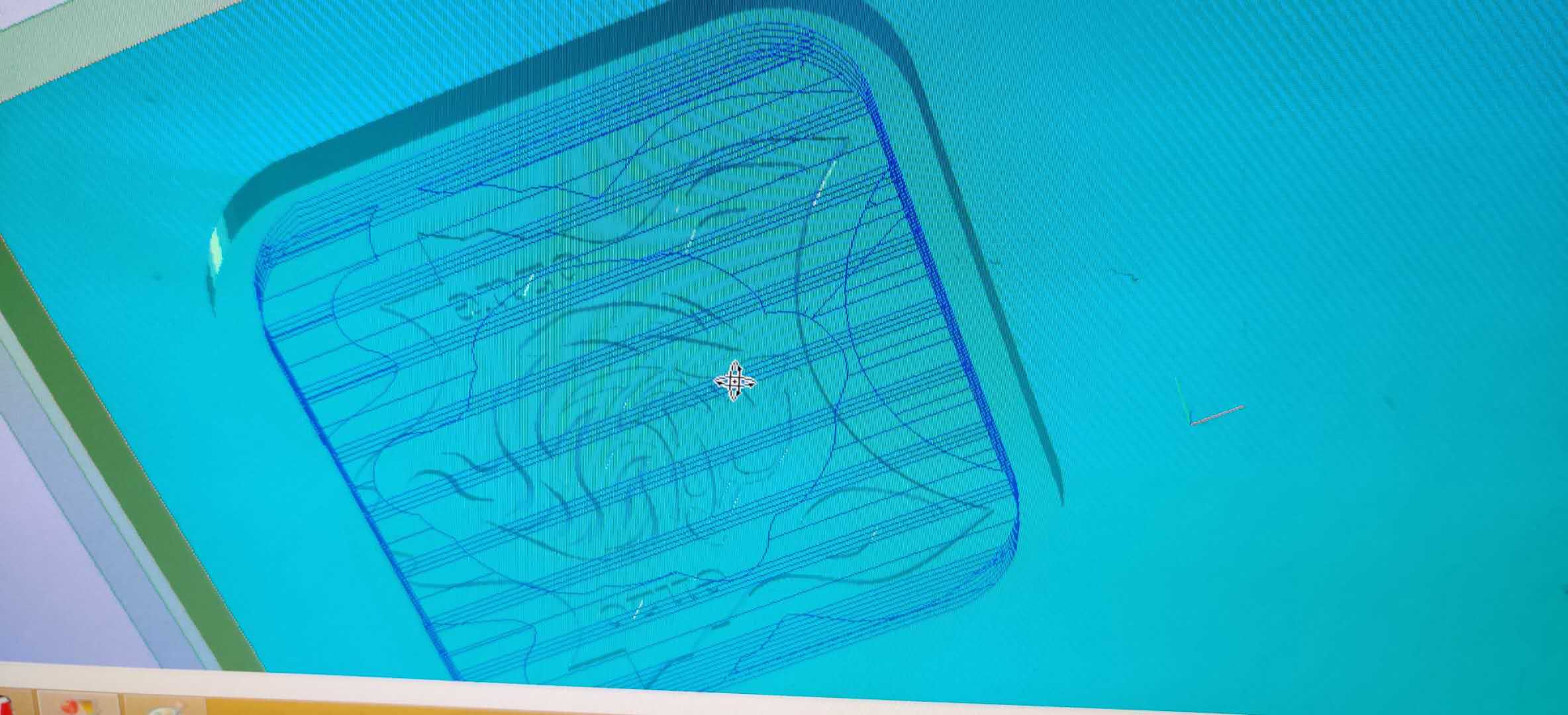
Once the design was reviewed and given the go-ahead by Saverio, I started creating the toolpaths with SRP Player software for the Roland SRM-20 milling machine. The software is relatively easy to use, where you define the top surface, cut area, depth, type of endmill, scan lines and cutting parameters for roughing and finishing. These are the notes I made for the entire process, which should give an overview of the process of creating the toolpaths. Adding all the images for this process on my site would mean that my repository will become the biggest in all of FabAcademy, so I have created a online slideshow to demonstrate the process. The only changes I had to make was in the definition of the cut area, which required a lot of number-crunching, because we had to find the position of the cut area relative to the center, whilst considering to leave a margin for the walls. I also increased the cutting speed for roughing and increased the path interval to almost 80% of the endmill size to reduce the time of milling.
The preview of the toolpaths was created, and after previewing the toolpath, it was evident that several features, including the name and the central design will not be very well defined. Therefore, I decided to run a second finishing toolpath, using a 0.1mm diameter ball endmill. The preview was much more promising, with evidence of more detail in the central design, and an engraving-like finish for the name. The .stl file was exported into a file for the SRM-20 VPanel.
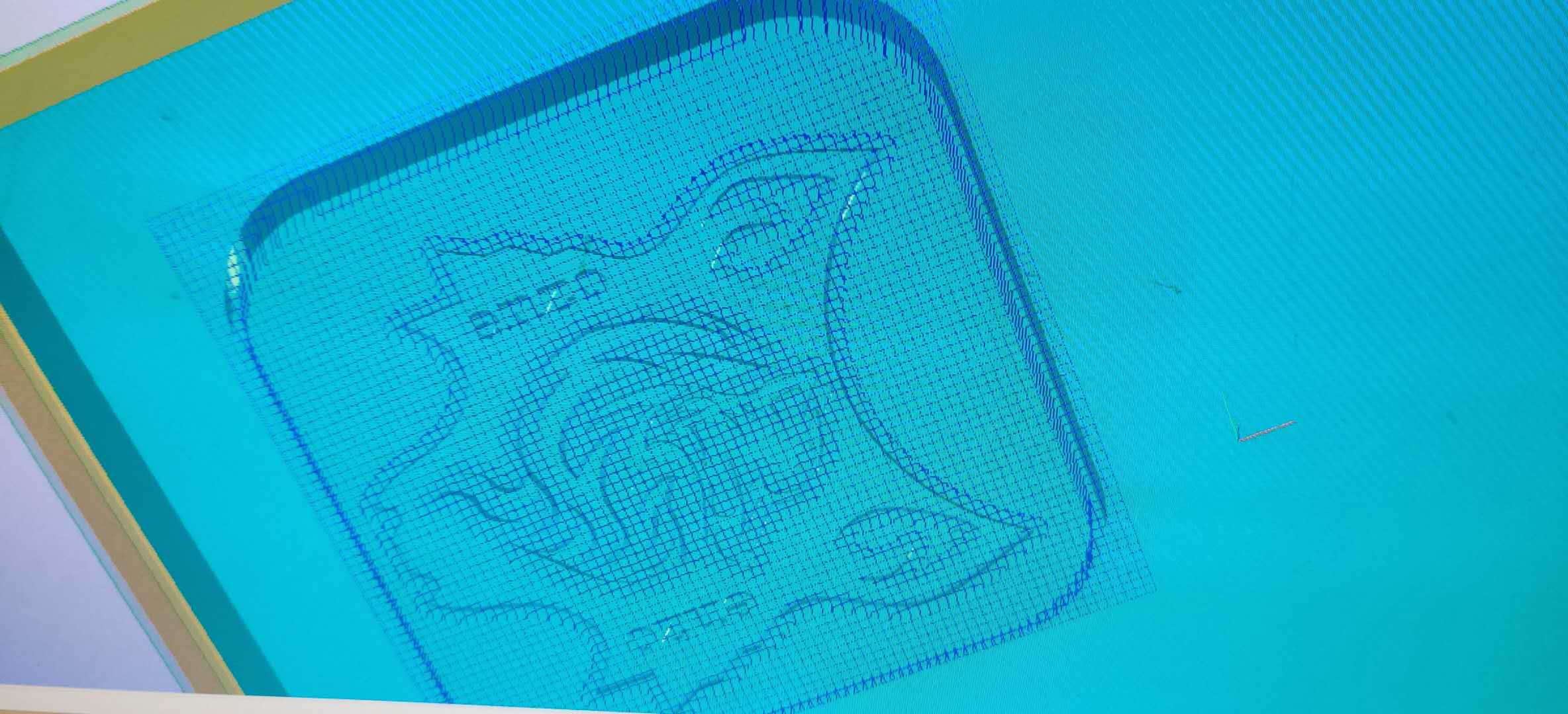
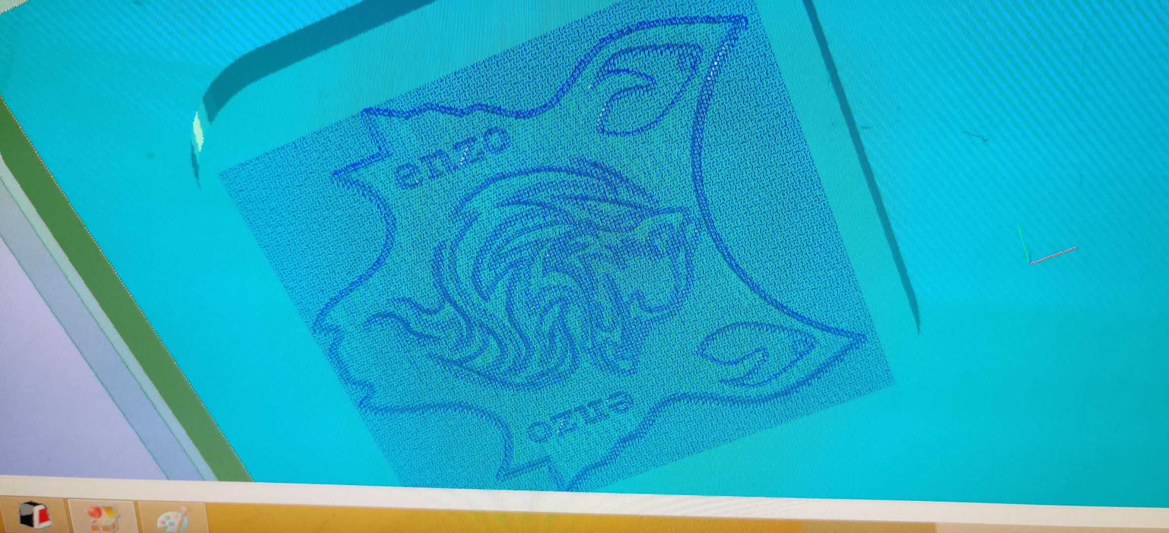
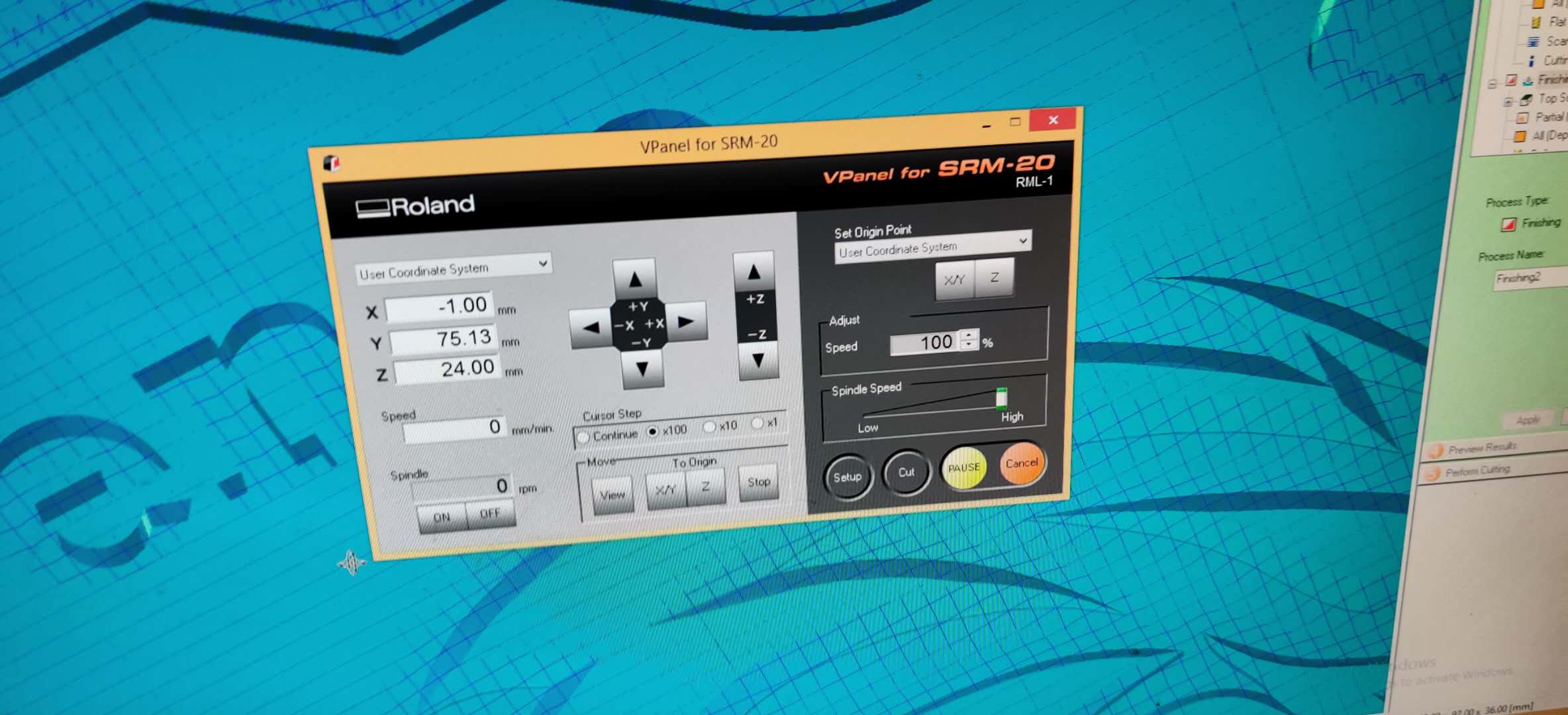
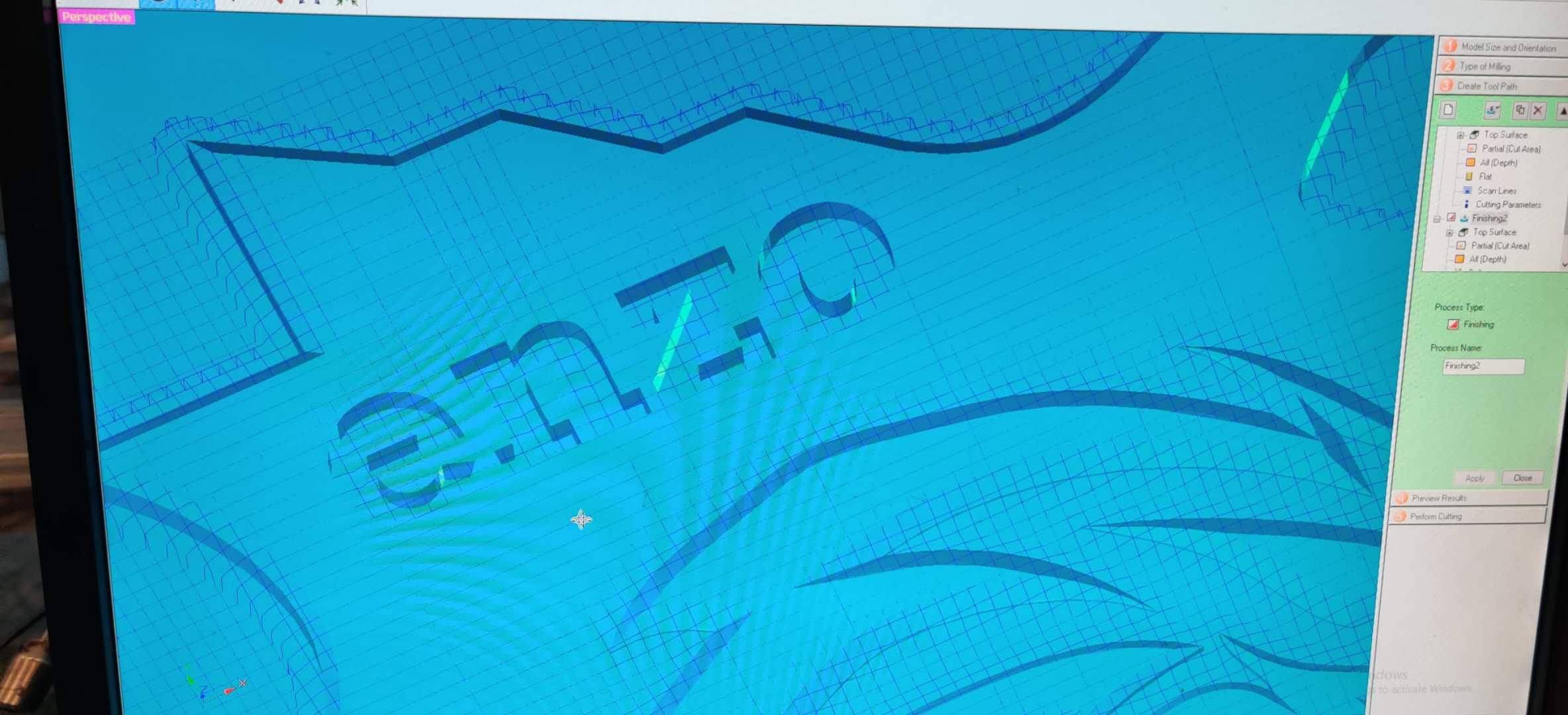 I then proceeded with preparing the wax block for milling. There was a unique block holder that Saverio manufactured, and we used that rather than the orange plate in the SRM20. Once the block was secured, we mounted it into the machine. I used a ruler from the edges to draw the intersect lines to determine the center. Once I had moved the machine to that point, I set the XY origin. Then, I inserted the 6mm flat endmill, increased the Z value to maximum, and moved the endmill, carefully avoiding the top securing block of wood to avoid breaking the endmill. I selected one point on the bottom left corner of the all, recorded its values, then only used that point to take every Z-axis origin when switching the other 2 endmills as well. When I outputed the finishing file, I decreased the speed of movement (not endmill rpm), and hovered the mouse over pause, just in case there was something wrong with the milling.
And there was something wrong with the milling because the milling had started in the bottom right, whereas I was expecting it to mill in the top left. I realized that whilst my Z-axis orientation in the SRP player was correct, I needed to swap the X- and Y-axis orientations. This meant re-doing the numbers for the cut area, but luckily the software remembered the other parameters. After exporting the new toolpaths with the corrected orientation, the milling process started correctly. I swapped the endmills twice for the 2 finishings, using the 2mm flat endmill for Finishing 1, and a 1mm ball endmill for Finishing 2. The final outcome was in much higher resolution than I had expected. The entire milling process, including swapping the endmills, took less than 1 hour, because my model was only one-part and relatively shallow.
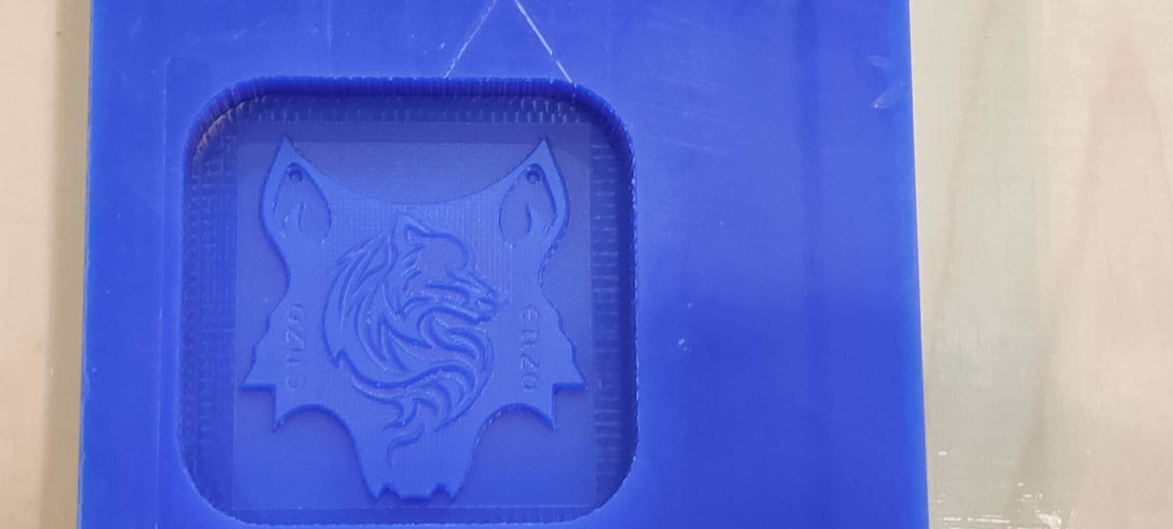
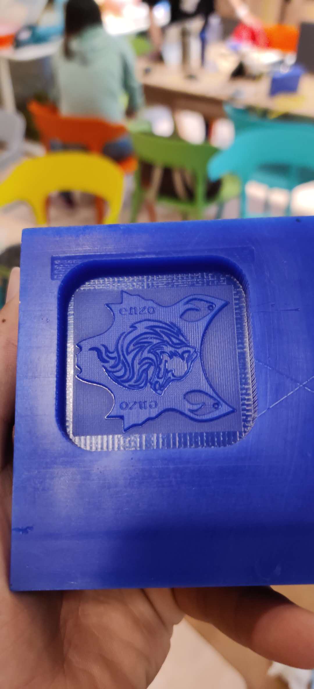
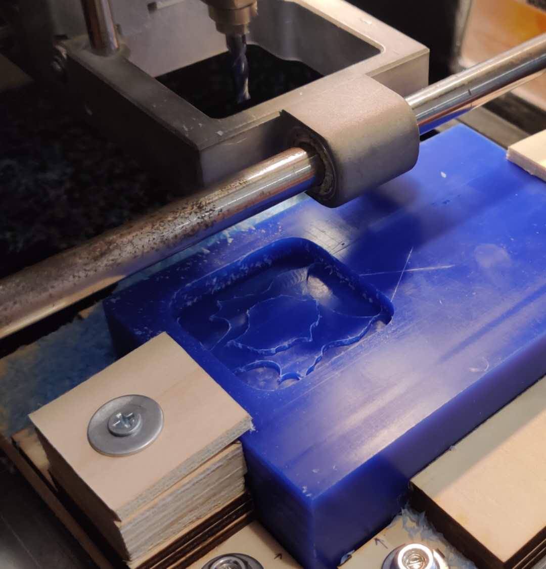
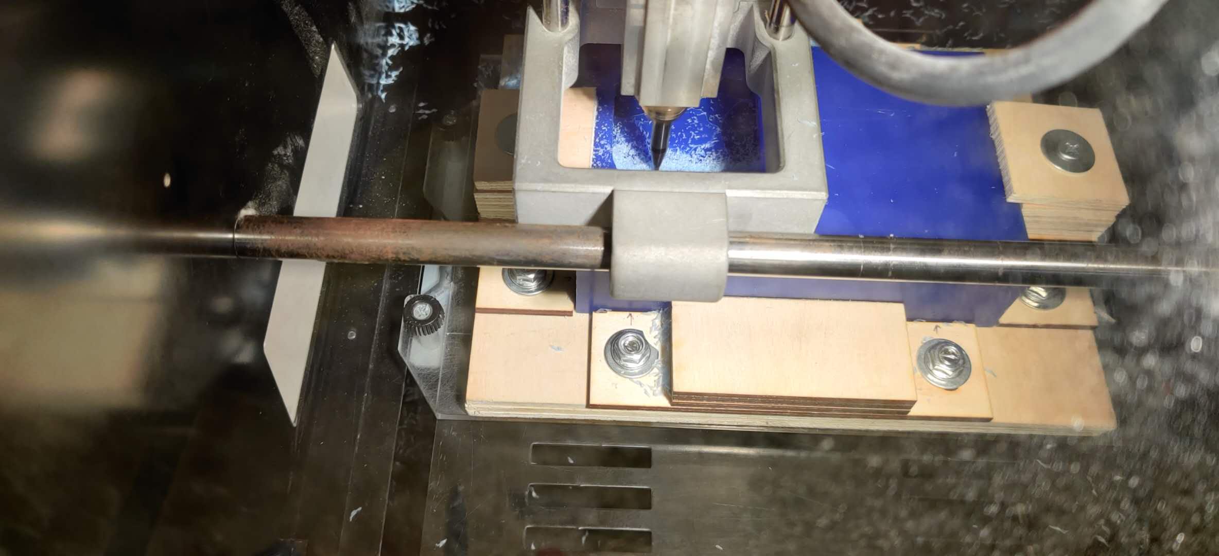 Just adding a quick note: I had mentioned earlier that the 95 degree walls would cause a problem, and they sort of did. When the milling process was operating, there was a very tiny margin outside the cavity where the endmill would occassionaly hit, because of the rising width (V-shaped) design of the endmill. I was concerned that I would break the endmill, but the endmill was fine, and the marks on my wax block were so minimal that the error would go unnoticed had it not been for the slight noise it made.
Ready for the molding process, we began reading the datasheets by Smooth-On to understand the mixing ratio.
Error!
When we opened the OOMOO Part A and Part B, they were not fluid. It appears that they had started curing during storage.
Disclaimer: The shelf life for Smooth-On parts is greatly less than a year.
The texture of the fluids was more like Jell-O now. So, we began looking for alternatives. Saverio found a 2-part fluids used by a student last year, which was specifically used for the skin-color like appearance. I learnt from Flavie's documentation that this would take around 3 hours to cure, which is certainly not 75 minutes, but at least it isn't 24 hours for the other one we had. Unfortunately, there was no documentation as to the ratio of Part A and Part B to use, and I don't think there was a datasheet as it was bought from a random Chinese supplier. I just assumed it would be 1:1 by mass, and poured 10g of Part A and Part B each. I then stirred the mixture until a color-change, carefully scraping the edges of the mixing cup, and ensuring no bubbles were made. When the mixture was ready for pouring into the wax master, I followed Saverio's advice, and painted the mixture on top of the design with a paint brush initially. Then, I selected an area outside of the design, started pouring the silicone as slowly as possible, in the same spot (to avoid creating air bubbles), whilst gradually increasing the height of pouring to make a thin stream. The fluid eventually encapsulated the entire cavity very neatly, with almost no air bubbles visible to the human eye. I now started waiting.
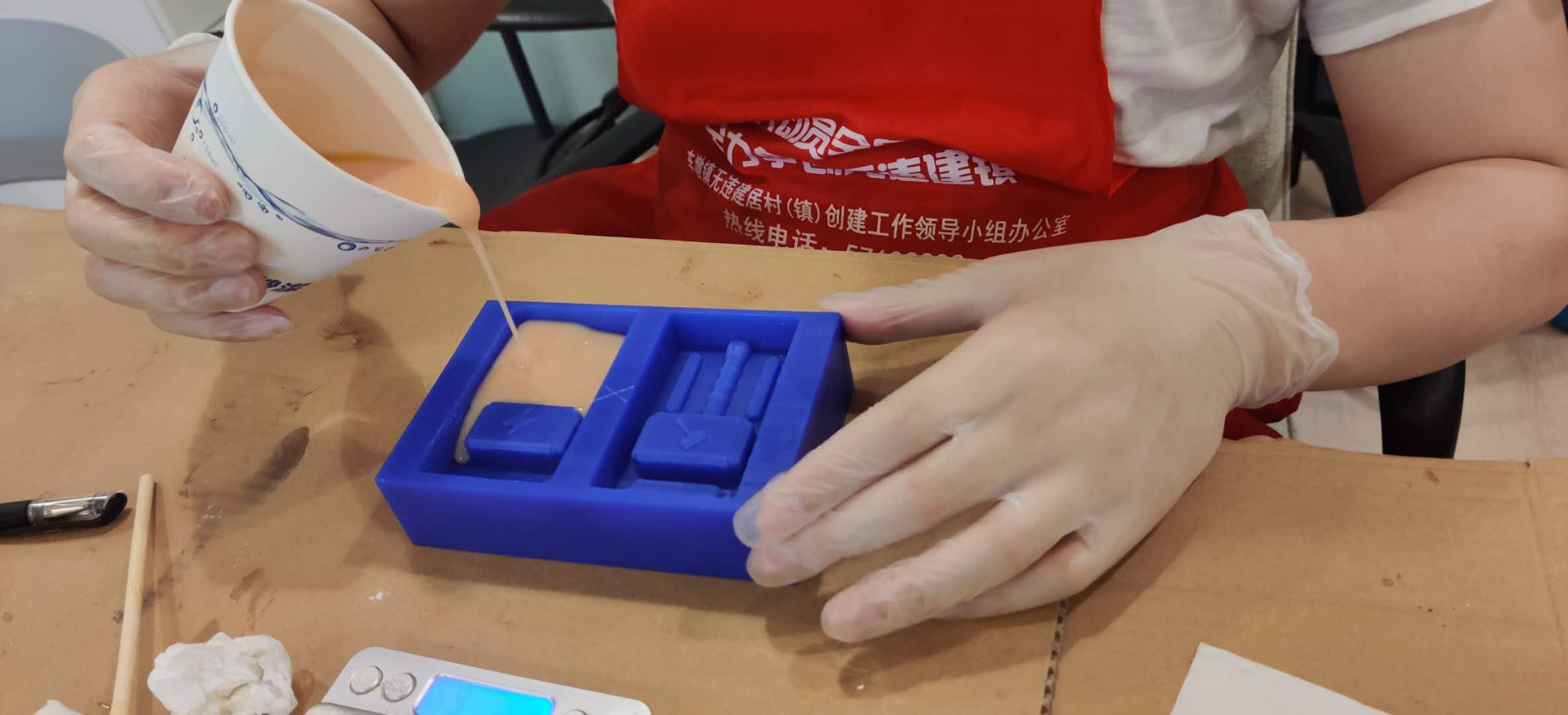 Not me, but same technique (@pan.cheng)
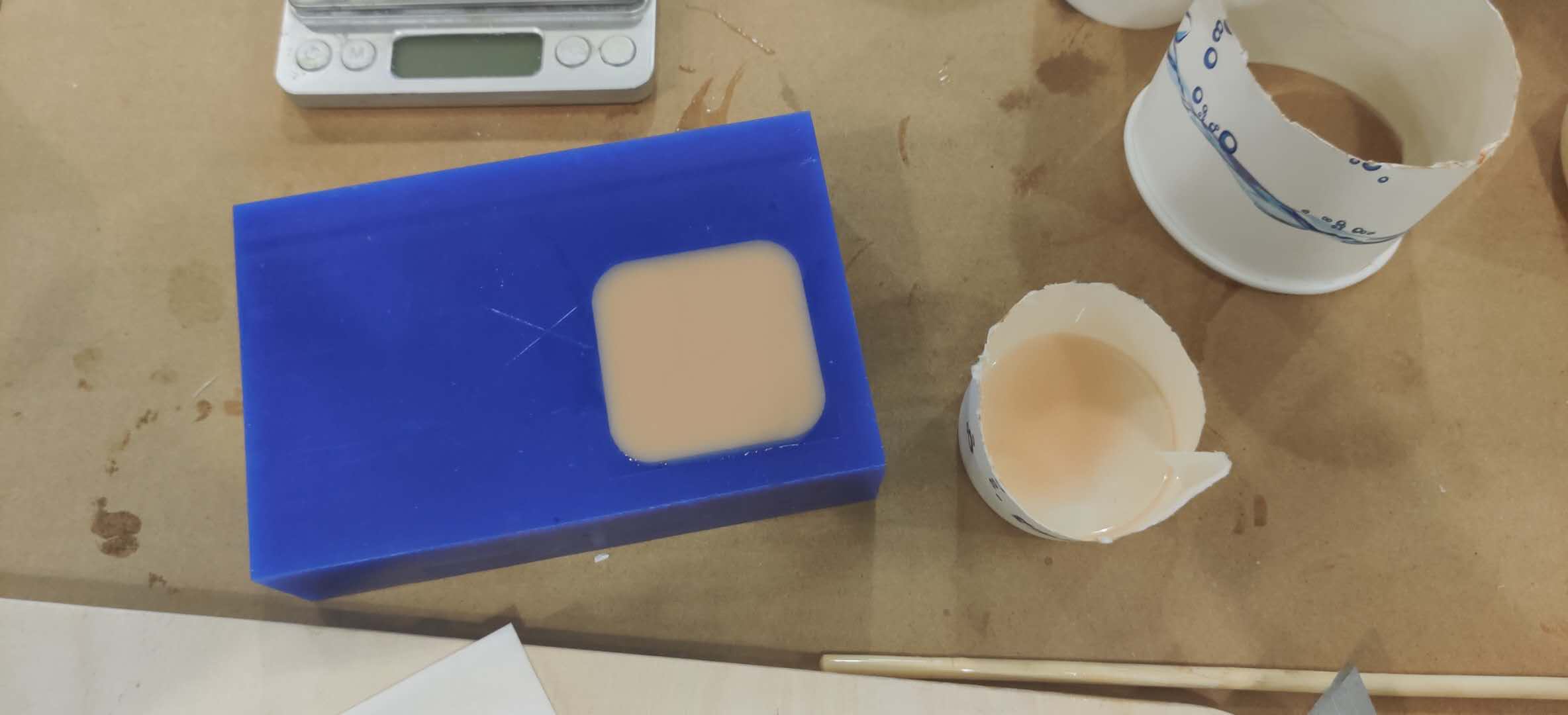 After waiting for around 1.5-2 hours, I decided to check on the mold, and realized that it wasn't fluid or sticky anymore. I ensured that it was mostly solid, and it was. Since the silicone is so flexible, I carefully peeled away from one edge, and the mold lifted right away. Again, I was impressed with the detail transferred to the mold.
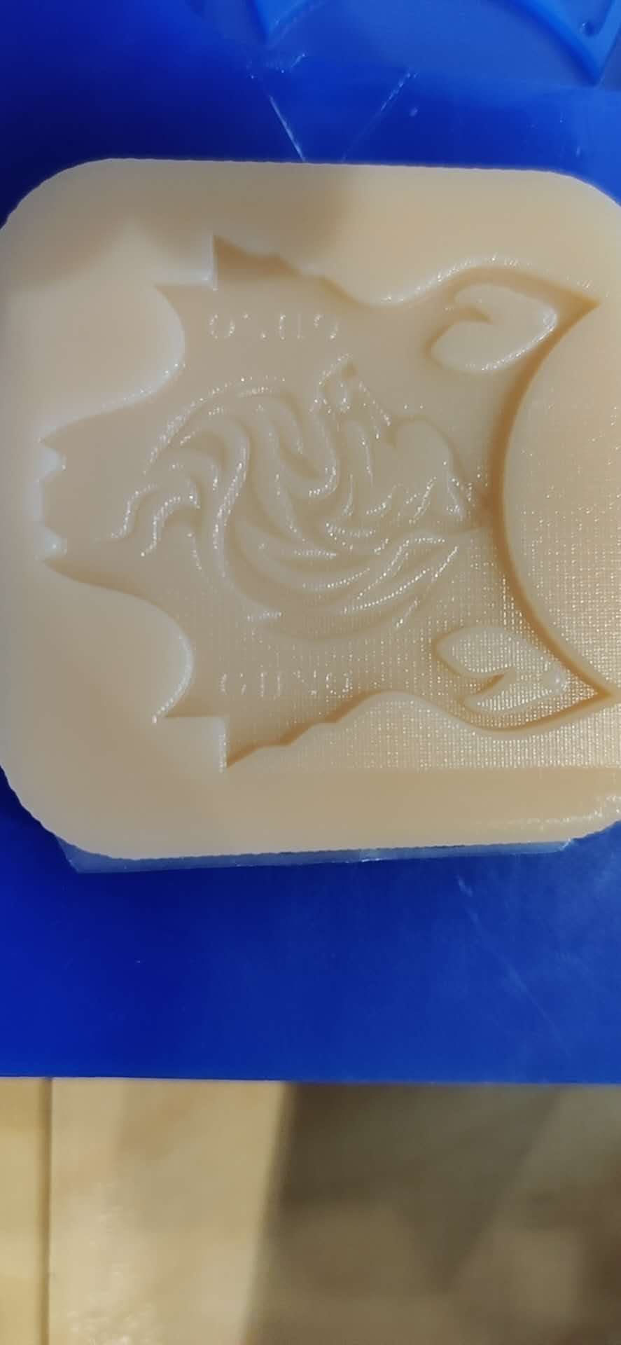
Now that the mold was ready, I started melting the bismuth alloy, which can be done over a hot plate in a common cooking pot. Quickly, the metal had already melted. Part of the reason that I chose metal, apart from a more desirable finish, was that it would cast really quick, since my mold is one-part, flat, and wide, so the heat would dissipate quickly. I used the talc powder on the mold, carefully ensuring that only a thin layer was placed on the mold. I poured the molten bismuth over my mold, not really knowing what to expect. I noticed that the metal had overflowed, so I had possibly added too much metal. After it cooled down within 5 minutes, I removed it from the mold,
and it was in no registerable shape or detail. It looked exactly the same as the metal I had started with.
😐
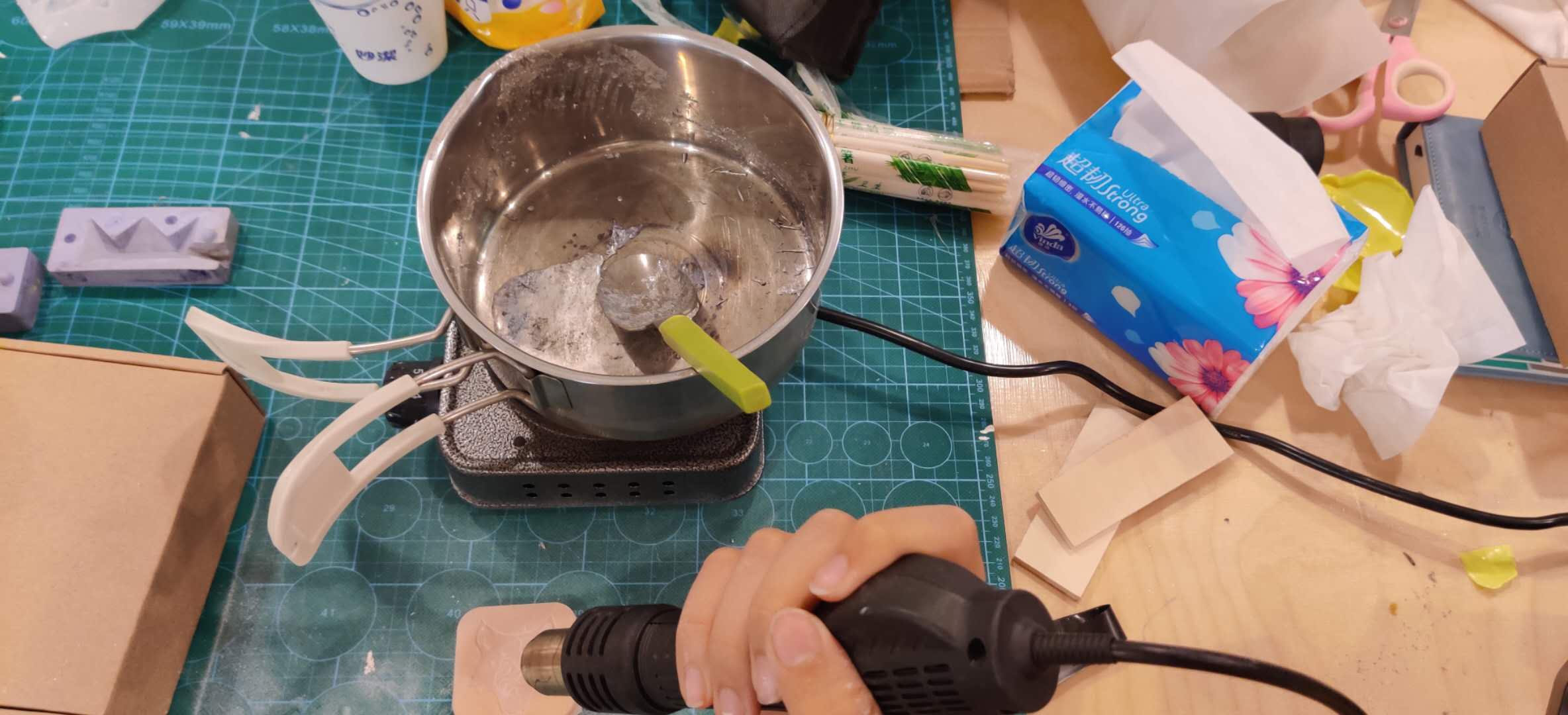
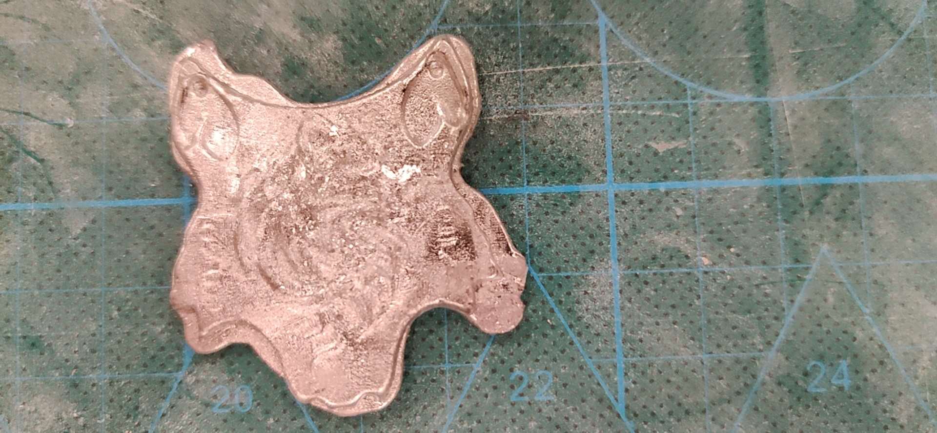
I confirmed with my instructor that I was overflowing the metal, so once I re-melted the metal, and casted it again, this time making sure that I was only pouring in one place to allow the metal to flow into its shape. The big reveal was another dissapointment. Whilst the outline shape had improved comparatively, but the details were still terrible. At this point, my instructor suggested using a different material for casting, such as polyurethane resin. However, I noticed that some details were recognizable, but not properly finished. I used steel wool extensively, and the finishing improved immensely. So there was hope for metal casting after all! I decided to a final, 3rd casting, carefully pouring the metal, squeezing the ends of the silicone to guide the viscous metal, and using the wide part of an exacto knife to guide the metal into the small details of the mold, such as the sharp corners of the outline. An additional thing I did was use a hot air soldering gun to heat the metal to make a finer, even surface at the back. The problem in the previous castings was that the rear part of the cast was uneven, so re-heating it meant that the rear surface was much more even.
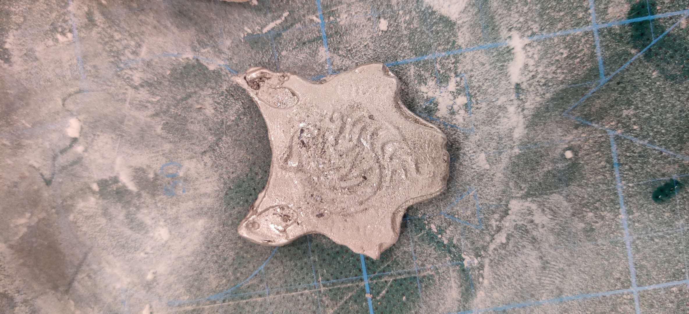
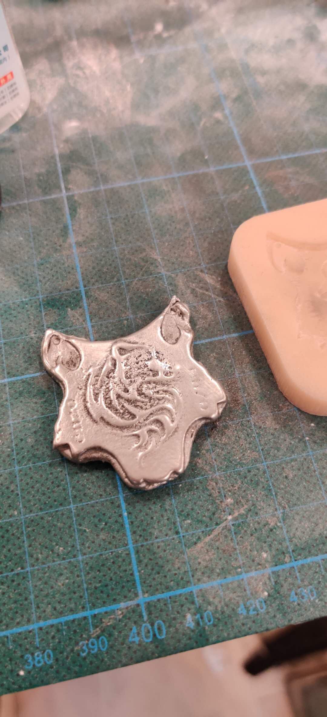
The 3rd casting was immensely better in terms of the outline finish and detail, but there were grooves in the design which didn't look too great.

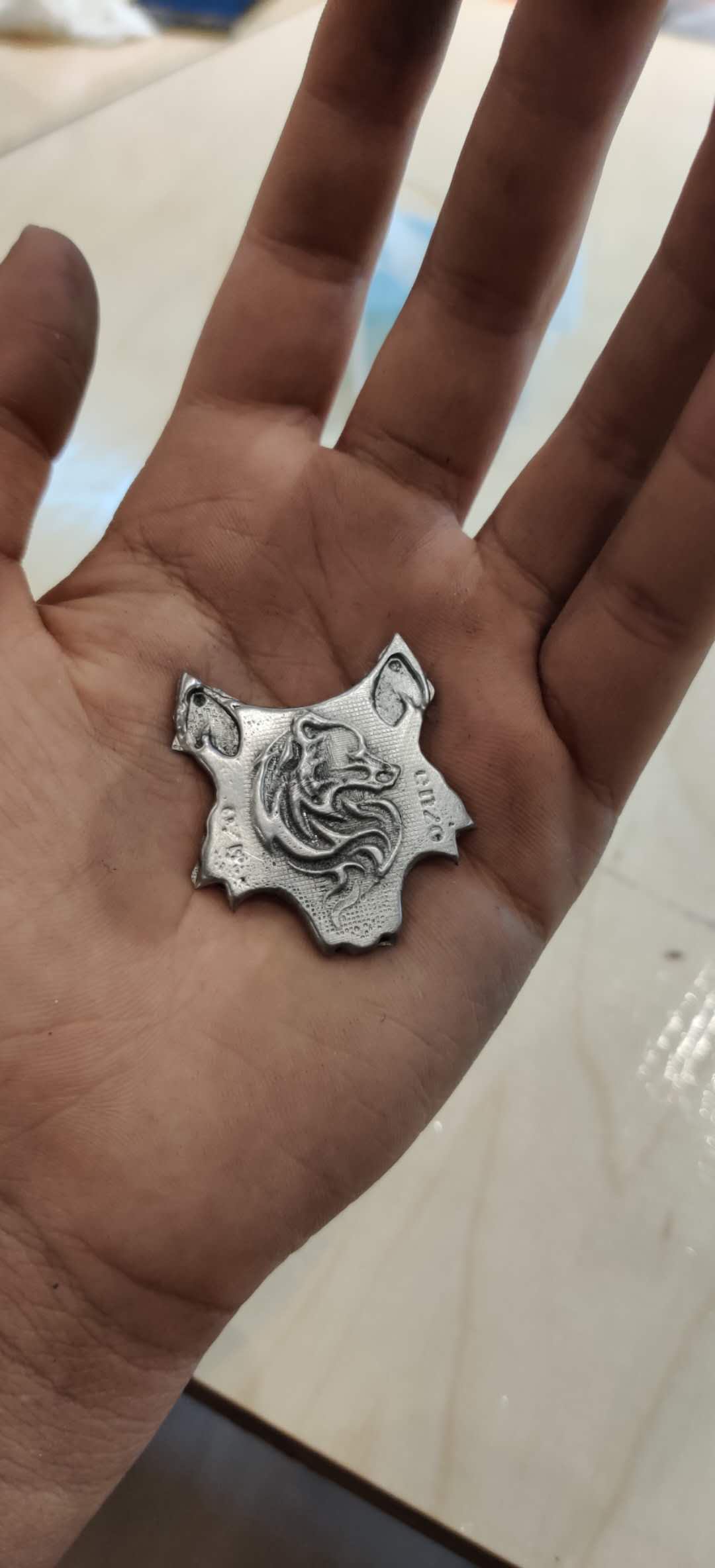
Disclaimer: Avoid talc powder for metal casting
CONTROVERSIAL?
Yes.
I know many documentations recommend it. But in my experience, the powder only damaged the surface finish. Before my third casting, I cleaned the mold with water. I used the absolutely finest layer of powder, dusted it to the point where no one would realize that there was any on at all. Yet, the details on the surface in certain areas still had minute grooves. I realized that there must have been some powder left which I could not clean (I did dry the mold very well), and if I hadn't added it, then possibly the finish would have been better.
Update:
I cannot confidently claim that talc powder damaged the surface finish on my casting, because I have not evaluated any differences by casting with a mold without any powder at all. Concerning the surface finish, an alternative explaination could be that there was an issue with my lab's bismuth, as it had been melted and re-formed too many times.
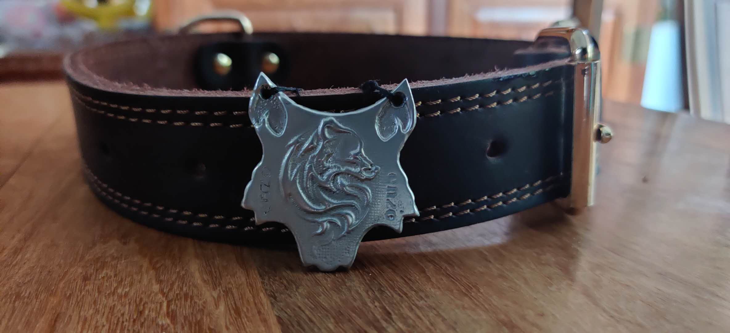
Anyways, I took the piece home, and etched into the grooves to make the 'ENZO' name clearer, used a thin screwdriver to make the holes, filed the outline shape, improved the imperfections on top surface so it is very smooth now, and finally polished it with steel wool. The end result, in my opinion, was excellent, especially considering that this is my first ever molding and casting project. I could have improved the finish even further, but in the end I decided to leave it as it is, because the imperfections added to the overall appearance of the piece. The last step was to put a thread through the holes, tie a knot, and then attach it to my dog's collar.
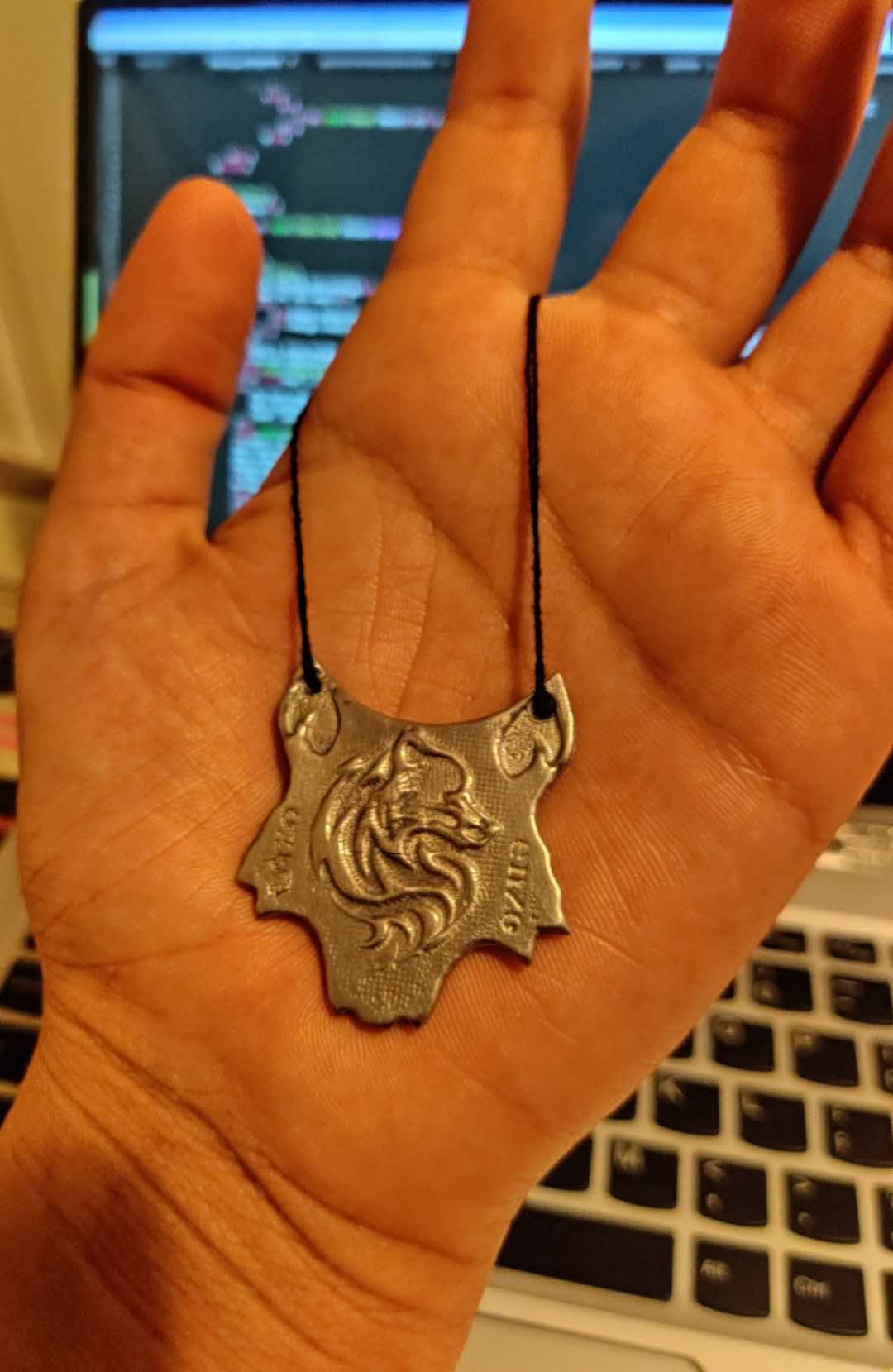
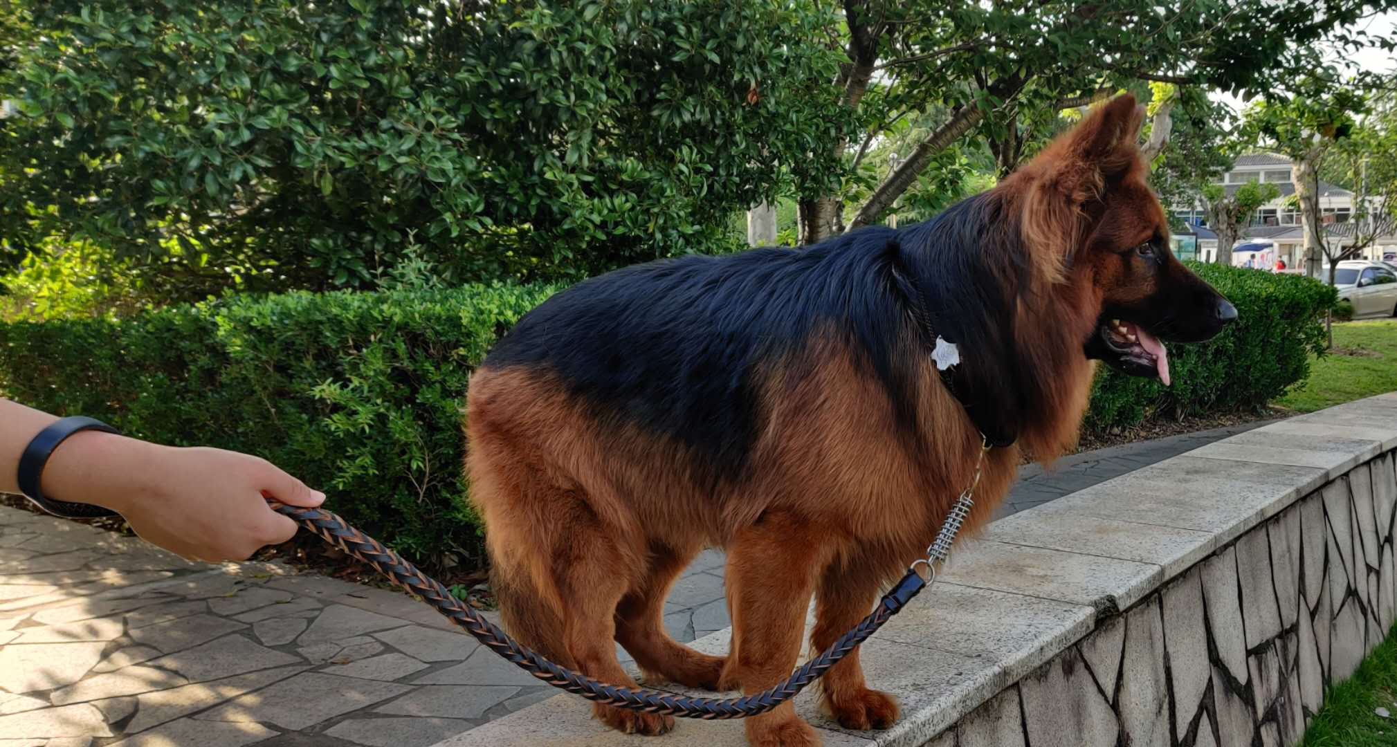
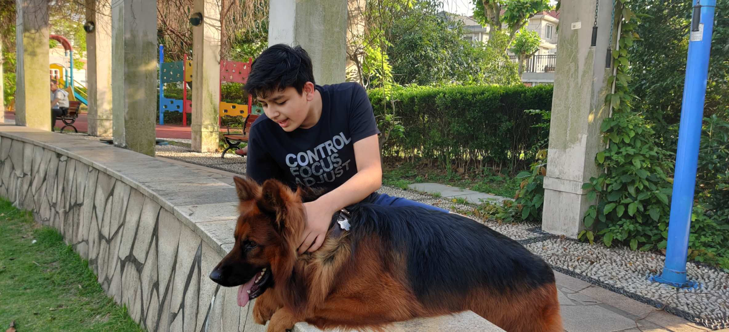
The final test was very successful. The collar tag stayed intact, even after Enzo running around and jumping quite a lot. I might reinforce the thread further, but overall, this is a project that myself and my dog will use and enjoy for a long time. Also, the challenging part of milling the wax, creating the mold, and casting was completed in one day, which was an added bonus for me. :)
hero shots:
 Click here to download the Dog Nametag Blank
 Click here to download the Dog Nametag Mold Blank
I have attached the designs, which are completely blank. So, if you want to replicate my project, you can simply add your pet's name in the design, and then produce the toolpaths.