Interface and Application Programming
Tasks for this week:
- Write an application that interfaces a user with an input &/or output device that you made.
Part 1- Using Processing 3
Processing 3 was a new IDE that I learnt this week. The concept that we planned for this was to control an interface on the computer, using a physical input device, such as a potentiometer. Since it was the first attempt using Processing for many students, we developed the code as a class this week, with the guidance of our instructor. We decided to create an interface where the the color of the canvas is changed by rotating the potentiometer. The following is the code that we created:
void setup() {
// initialize serial communication at 9600 bits per second:
Serial.begin(115200);
}
void loop() {
int value = analogRead(A0);
value = map(value, 0, 1023, 0, 255);
Serial.println(value);
delay(100);
}
This was simply the AnalogReadSerial example uploaded onto the the Arduino, modified slightly to map the values until 1023 to a range from 0 to 255. Furthermore, we added the println(value) function so that each value will be registered on the serial monitor. Once this code was uploaded on the Arduino board, we coded the following in Processing:
import processing.serial.*;
Serial myPort;
float val;
void setup()
{
String portName = Serial.list()[0];
myPort = new Serial(this, "COM3", 115200);
size(640, 640);
myPort.bufferUntil ( '\n' ); // Receiving the data from the Arduino IDE
}
void serialEvent (Serial myPort) {
val = float (myPort.readStringUntil ( '\n' ) ) ; // Changing the background color according to received data
}
void draw()
{
println(val);
background(0, 0, val);
}
The most important aspects of the code above is the definition of the size of the canvas, which is the interface where the user can see changes in the color. Also, In the final line of code (0,0,val), that is the color value designation to RGB. By having the val in the blue section, the canvas color would be blue, and it would change color to different shades of blue. One improvement for this experimentation in the future would be figuring out how to control the color of the other 2 color values as well, but that would probably involve 2 more input devices.
We faced two main errors with this code. The first one was that the value we were registering on the serial monitor was a string, whereas in this code, the value is a float (decimal point values, not only integers). Our solution to this was to classify the strings that the was read by Processing as a float, and then the code worked.
Another error we faced invovled struggles with uploading the code, but the solution was that we were missing quotation marks in the port designation.
Part 2- MIT App Inventor
The next thing I wanted to accomplish was making an app for the phone. I had been looking forward to this week for a long time, and couldn't wait to start making an app that could control output devices or measure data from an input device. MIT App Inventor has a learning curve associated with it, but is still relatively easy as it does not involve proper code and is programmed with blocks, similar to Scratch. Nevertheless, I still followed these tutorials from a YouTube channel named 'How To Mechatronics', and this is a channel I highly recommend for electronics assignments. The Android application I created would be able to control the color of a RGB LED. I successfully created the app, and here are some screenshots:
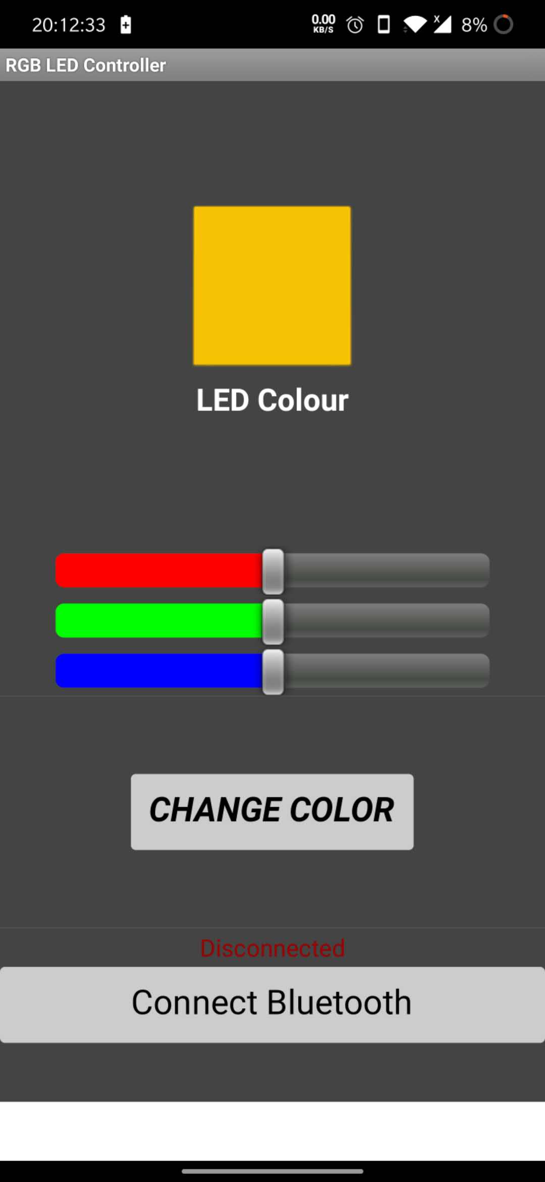
Error! So, this tutorial required a HC-05 bluetooth module, which we currently did not have in the lab. So, whilst the app was made, I couldn't test it yet. The component has been ordered, and I will update this page with documentation of it working soon!
Update- The components finally arrived, and I used the following schematic to create the circuit.
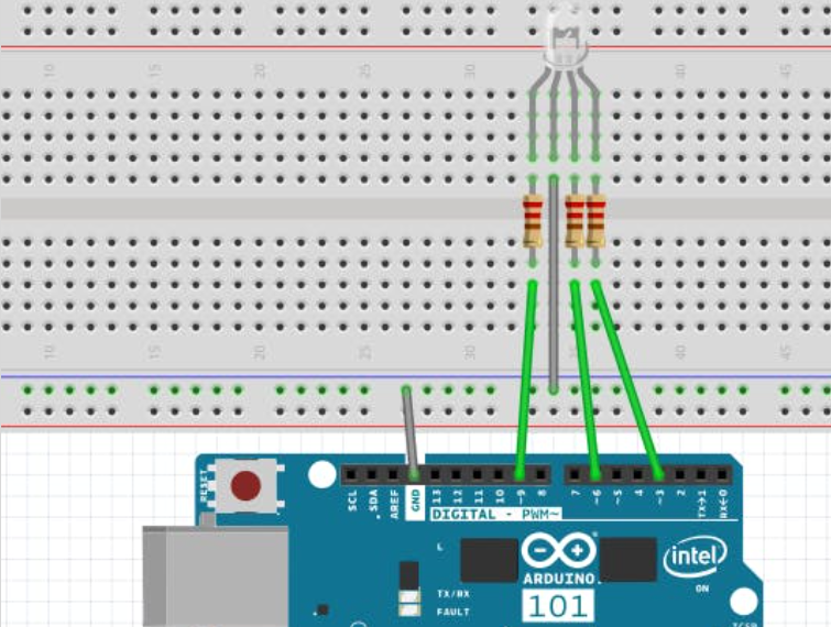
The following is the code to upload to the Arduino-
#define max_char 12
char message[max_char]; // stores you message
char r_char; // reads each character
byte index = 0; // defines the position into your array
int i;
int redPin = 11; // Red RGB pin -> D11
int greenPin = 10; // Green RGB pin -> D10
int bluePin = 9; // Blue RGB pin -> D9
String redTempValue; // Red RGB pin -> D11
String greenTempValue; // Green RGB pin -> D10
String blueTempValue; // Blue RGB pin -> D9
int flag = 0;
char currentColor;
void setup() {
pinMode(redPin,OUTPUT);
pinMode(bluePin,OUTPUT);
pinMode(greenPin, OUTPUT);
// initialize serial communication at 9600 bits per second:
Serial.begin(9600);
}
void loop() {
//while is reading the message
while(Serial.available() > 0){
flag = 0;
//the message can have up to 12 characters
if(index < (max_char-1)){
r_char = Serial.read(); // Reads a character
message[index] = r_char; // Stores the character in message array
if(r_char=='R'){
currentColor = 'R';
redTempValue = "";
}
else if(r_char=='G'){
currentColor = 'G';
greenTempValue = "";
}
else if(r_char=='B'){
currentColor = 'B';
blueTempValue = "";
}
if(currentColor == 'R' && r_char!='R'){
redTempValue += r_char;
}
else if(currentColor == 'G' && r_char!='G'){
greenTempValue += r_char;
}
else if(currentColor == 'B' && r_char!='B'){
blueTempValue += r_char;
}
index++; // Increment position
message[index] = '\0'; // Delete the last position
}
}
if(flag == 0){
analogWrite(redPin, 255-redTempValue.toInt());
analogWrite(greenPin, 255-greenTempValue.toInt());
analogWrite(bluePin, 255-blueTempValue.toInt());
/*Serial.print('R');
Serial.println(redTempValue);
Serial.print('G');
Serial.println(greenTempValue);
Serial.print('B');
Serial.println(blueTempValue);
Serial.print("MESSAGE ");*/
Serial.println(message);
flag=1;
for(i=0; i<12; i++){
message[i] = '\0';
}
//resests the index
index=0;
}
}
It took a while for my phone to recognize the HC-05 module, and I could not figure out the reason why it was not working. The red LED on the module was also not lighting up, which led me to believe that there was an issue with the connections. I swapped out the wires, and the issue was to do with a broken wire after all. The LED did turn on, and my phone recognized the module. I was successfully able to control the color of the LED, but its brightness was very dim. I swapped the resistors with weaker ones, and the brightness was improved.
Looking forward, I will try and connect and LED neopixel strip, which I might be able to attach to the lamp I made on the Shopbot.
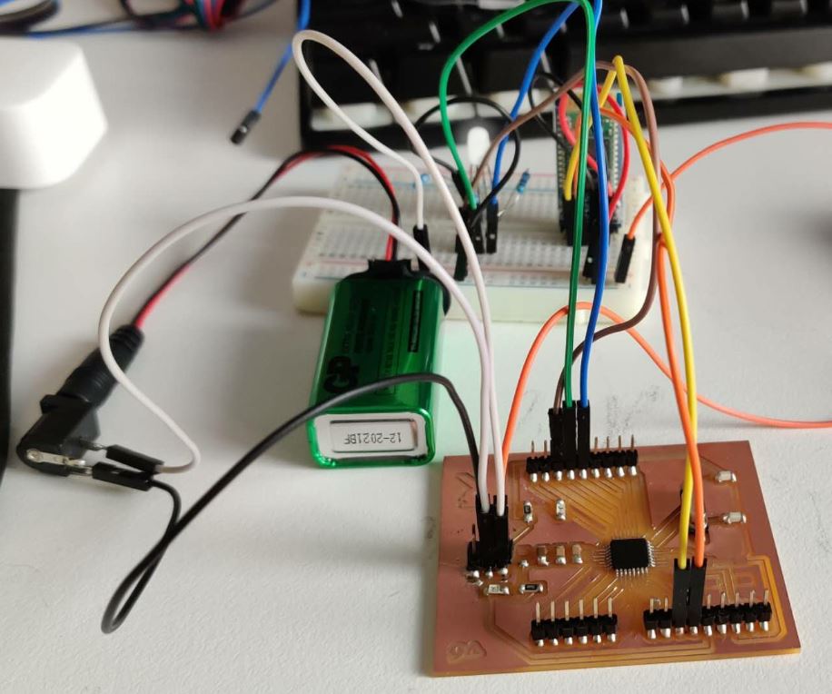
Hero Shots:
Update 2 (16/7/2020): I finally have my Rupino working! After 7 attempts, the 8th one worked succcesfully. I uploaded the code above to the arduino, and made the connections according to my board layout. Now, the circuit worked with the Rupino, and this assignment is fully completed.
Hero Shot:
I also re-created the processing example interface with my Rupino. Here is the hero video: