Introduction
This page serves the purpose of documenting my fabrication process for the final project, as well as all the necessary files for you, the reader, to access and replicate. It is divided up into sections that cover different digital fabrication processes. At the end of each section are the key takeaway points.
Project Management, Principles and Practices
LinkCAD, 3D Printing and Computer-Controlled Cutting
Conception of Idea:
I initially wanted to design and 3D print the complete structure, however I was limited by our printer's capability to print a structure this big. Also, there were concerns regarding the tensile strength of the PLA material when considering the large torque each motor produces.
IMAGE FROM CAD WEEKThe solution was to use aluminium rails used in the Mechanical and Machine Design week, and to attach 3d printed motor mounts using 3m bolts and t-nuts. I designed 4 side motor mounts, a simple base plate for the bottom motor, and a master top mount that latches onto 4 side mounts and also houses the top motor. The accuracy of latching the top mount onto the side mounts, as well as the depth for the motors, was achieved by inserting a Nema-17 1.5A motor model from the McMaster-Carr catalogue. The design of the top mount was created by modelling one side, and using the Circular Rotation tool to make 4 sides at 90 degrees to each other.
CAD PHOTO OF MOUNT AND TOP MOUNT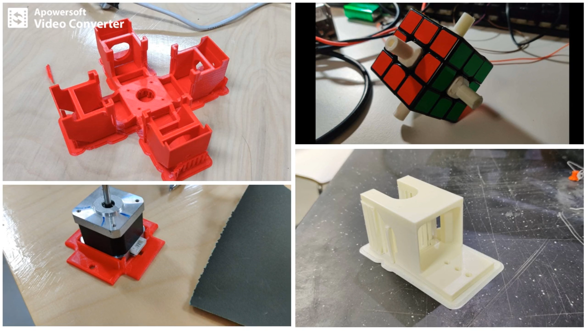
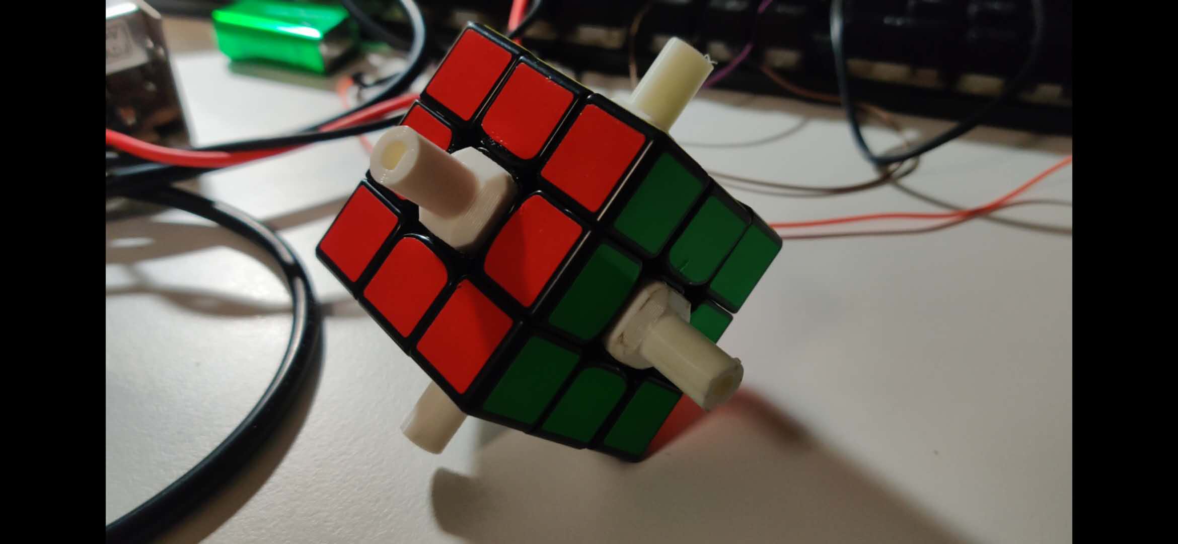
I also printed connectors for the Nema 17 motors to connect directly into the center-cap area. This was definitely the most challenging part to design, since I was using the MoYu WeiLong GTS2 cube, and I couldn't find the size and depth of the center cap. This was difficult to design and I must have printed 6-8 times before getting the right size, even after measuring with a vernier caliper. The last size is still a tight fit, any you might need to fit the edges, but after that it fits well. When you open the file, it might be scaled incorrectly. Printing at 10% scale.
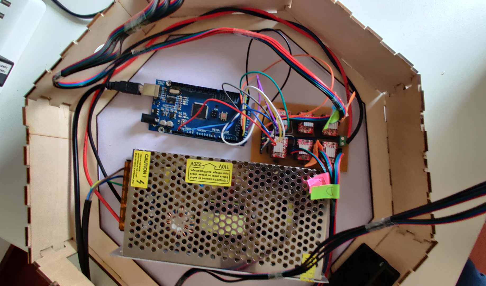
For 2D CAD and computer controlled cutting, I used maker case to make a octogonal box. I then opened the file in Inkscape, and made some changes. I added my logo, my name, and made cutouts for the power cord, and 2 vents on opposite sides for the ventilation by fan. I also cut out the bottom piece, leaving a border along the edges for easier access to the electronics. My initial plan was to mount the electronics upside down on the underbelly of the top piece; however, the 3mm plywood that I cut on the laser cutter was too thin to support the electronics and the mounted frame on top, so I cut a hexagonal plate of 1.5cm thickness on a bandsaw to be attached with 8X 2.5cm velcro strips glued onto the border, on which I screwed in the power supply and used double-sided tape for the driver board and arduino.
Modifications to the initial designs: Looking at this structure in retrospect, I think that it is too rigid. After discussing the constant jamming issue with Professor Neil during my final project presentation, he suggested loosening the t-nuts, to give more room for the motors to move, and to reduce the pressure on the connectors at the center cap location, which would result in tightened movements i.e. higher chances of jamming up. So, returning to the project, I loosened the attachments to the aluminium rail, and in this loose form, the robot's probability of solving increased significantly. There was very less jamming up, although it wasn't non-existent. If I were to make a V2 of this project, I might make the entire structure out of printed PLA. It's lower torsional rigidity might actually be beneficial in this case.
Electronics Design and Production, Output Devices
This section includes documentation for the fabrication of the milled Rupino, as well as the 6 driver board that I specifically designed for this project, since there was no commercial alternative, and testing on breadboards was useless.
The Rupino was possibly the most difficult thing for me to make. It spanned 6 re-designs and 8 boards, before it was finally working. Here are a list of things I tried: new layouts, better soldering, burning bootloader of the Arduino Pro or Pro Mini profile, someone else's board design, someone else's help to solder my board, using a pre-burnt bootloaded chip, thickening the traces, cleaning with steel wool and tweezers under a magnifying glass, cleaning with alchol and brush, using brand new endmills, just to name a few.
Eventually, some modifications to the thickness of the trace, but mainly my best attempt of soldering resulted in a working Rupino. However, making the Rupino work took me such a long time that I tested the prototype with an Arduino Mega.
The next part to talk about are the drivers, which was a major issue that nearly resulted in this project never working. I followed the same schematic from the stepper motor with a breadboard assignment from the Output Devices week, and managed to make 1 motor move. Pretty simple. Now, all I had to do was to replicate this 5 more times, and then I would be ready to move onto the next step.
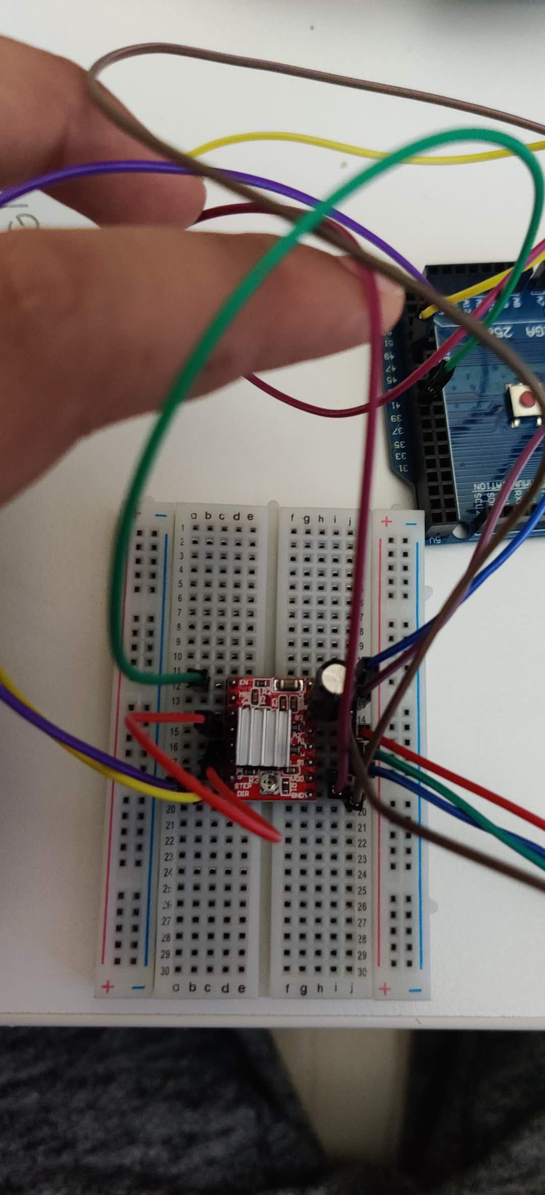
I only had 3 breadboards on hand, so that meant making connections for 2 drivers on each board. I prepared 1 breadboard with 2 drivers, but none of the motors would move. I re-checked the connections, made sure that the power supply connection was fine. At this point, I noticed that the wire to which the power supply connection was connected to the breadboard was heating up. Although, I felt that this was expected since there are now 2 drivers connected. So, I decided to take out 1 driver and see if 1 motor would still work. When removing the driver, the board got so hot, that the driver had melted from the underside. I had fried my first driver from many to come. The breadboard was also extremely hot underneath. After letting it cool for nearly 20 minutes, I tested the remaining driver. And, it wouldnt work. I replaced the connections onto a brand new breadboard, and it again didn't work. So that's 2 drivers gone. I then proceeded to fry every single driver I had and all my remaining breadboards, except one, where I noticed some sparks from the power supply connection and immediately shut off the system. If I couldn't get 2 drivers to work at the same time, how would I make 6 work.
I returned to the lab, scavenged brand new drivers and breadboards, and thankfully the motors were turning now. I replaced each motor connection and tested all 6 to ensure that the motors weren't damaged during my driver frying experience.
Clearly, I had to look for alternatives to a breadboard, which was only meant for prototyping. Anyways, Neil discourages us from using them. I tried finding commercial driver boards, but they could only house 3 drivers. There was a board I found that could house 5, but it was only meant for 3d printer applications. So, I decided to make my own driver board.
This next section that I am about to talk about is an achievement I am most proud of in my 16 years of life. It is also an excellent example of rapid prototyping in digital fabrication, since I went from conception of idea to a working, physical board within the space of 36 hours.
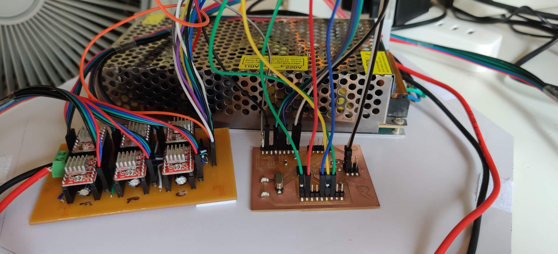
I planned to make a driver board for all 6 drivers to be mounted on. I followed the connections schematics for the driver as a basis for the pin connections. I initially started with the schematic consisting of nearly 72 pins, but I cut it down significantly by making a single pin for common connections, such as DISABLE, GND, VCC, VMOT etc. Other pins such as the STEP and DIRECTION, and MOTOR (2B,2A,1A,1B) pins would be individual for each driver. I made a 3X2 layout for the drivers in the board layout, and started making the common conenctions with traces. The size of the pins to mount the driver was deetermined with adding the A4998 component, and lining up all the 1X6 pins to its size. I decided to house the capacitor underneath the driver mount, just like in a commercial board. I also made the VMOT and GND traces run down the middle, and made them extremely thick for the power supply.
Since there were so many common connections, it wasn't feasible to join them all without any interference. Here, I learned the trick of jumping traces using a 0 ohm resistor. In some cases, I needed to jump 2 traces, but the gap between the pads of a resistor was again sufficient. Finally, all the traces for the common connections were done, but to actually connect them, I attached male pin headers, that are connected via jumper wires.
Soldering was quite a hectic process, since there were so many pads to solder. The benefit was that they were all pinheaders, and just a few jumper wires. Furthermore, the soldering was done on the underside of the board, so all components were out of the way. Here's a timelapse of me soldering:
I then proceeded to connect all the motors to my board, and when I opened the serial monitor, all motors were moving!
Input Devices, Programming and GUI
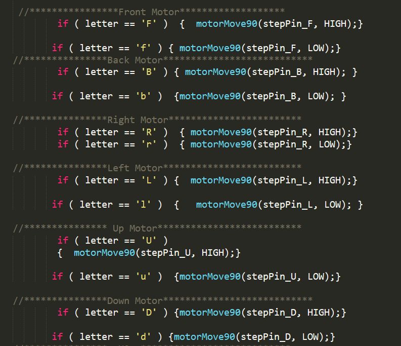
The input device for this project can be any keypad. The concept is similar to a simply Python keylogger; you assign a certain key to an action. So, in the code, you can sign each side respectively to turn the motor (turning the face by 90 degrees or 180 degrees is a pre-determined function from pycuber). Therefore, 'F' would result the front assigned motor to rotate clockwise once. A 'f' would cause the same rotation in the anticlockwise rotation. Once all sides were assigned (B,b, R,r, L,l, U,u, D,d), I had to room to make special combinations of unused letters to move a side 180 degrees (2 turns) or 270 degrees (3 turns), as well as having 2 opposing sides moving simultaneously. The permuatations of possibly are endless, and therefore result in a lot of combination shortcuts that only increase the speed of the solve.
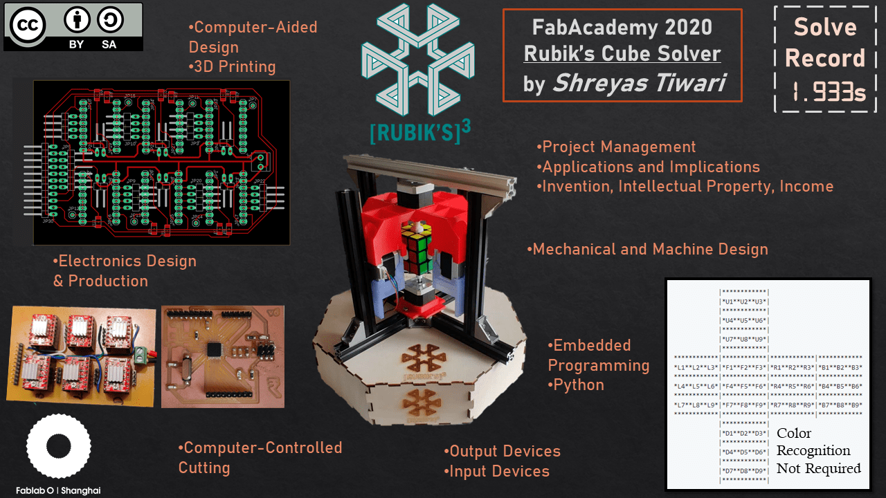
I will now briefly talk about how the code runs without requiring color recognition.
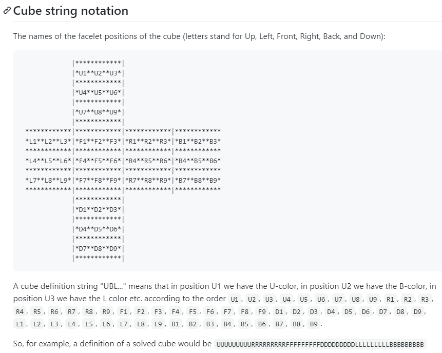
The image above demonstrates a net of the cube, where each face is assigned a letter, and each square on the face is assigned a number. Therefore, once a side is moved, the Kociemba algorithm understands where each individual square is now positioned. After all moves are made, the position of every square in the net is determined, then one of 20 algorithms are applied (depending on the position) to deliver the most optimal solution. further explanation
There is one constraint, and this is a MAJOR constraint: The cube must always start fully solved. And this is why the cube jamming up was such a major problem. Solving the cube whilst it is inside the rigid structure was complicated, stressful for my mental tolerance, and painful for my fingers. (Side note: I only realized later, that I could manually enter the color of the cube onto a online solver like CubeExplorer, and the cube would be solved with one-by-one steps from the solution. Why this didn't occur to me before, I have no clue, but at least it will help you.)
I wanted to use a Raspberry Pi to communicate with the Arduino, but I ran out of time, and any PC would work just fine. Basically, the python program a) determines the position, b) calculates the moves required to solve, c) sends the moves as a string in 2 parts (since it can be too long) to the Arduino through serial communication, which d) instructs the motors to move accordingly.
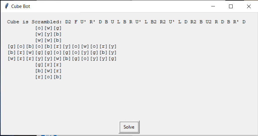
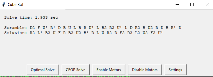
Finally, there is also an interface made by the eazygui python module. With this, you can manually control the motors, start scramble and solve, and it also reads the time for solve from the arduino.
This code part was definitely extremely difficult within the timeframe to complete, and my basic understanding of python would simply never have been able to achieve it. This programming section was completed greatly due to the assistance by Shawn Loe, an excellent mentor for my programming journey.
Update: In the code, there is a new feature that turns the motor off after a solve (disables them), to prevent overheating issues. There are also different speeds, so now the robot can solve a little slower, but at a higher probability of completing the solve without jamming up.
Concluding
Presentation Slide
 Slide
Slide
Presentation Video
VideoBill of Materials
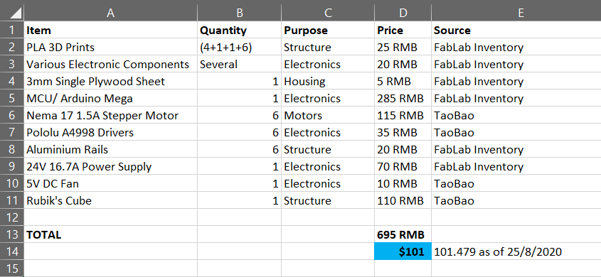
Please do keep in mind that this cost is only the cost of components used in the final project, and don't reflect the actual cost of development.
Please keep in mind the following license. The reasons to choose this license are explained here.

Rubik's Cubed by Shreyas Tiwari is licensed under a Creative Commons Attribution-ShareAlike 4.0 International License.
Instructions
Above was the end of the documentation. Here is a section that includes all the files, coupled with step-by-step instructions to replicate this project.
Print these files:
(1X Top Mount)
(4X Side Mount)
(1X Bottom Mount)
(6X Connectors, ONLY FOR MOYU WEILONG GTS2)
Print the connectors at 10% scale if it looks too big in the slicer software.
All files are Fusion 360 edition files, you can edit them if you want, and slice them in various softwares depending on the printer you have access to.
Go to Maker Case and laser cut a box for the housing. (No file included, since there are so many variations in the laser cutter settings, type of wood etc.)
Also cut aluminium rails according to a reasonable size. The measurements were simply approximate in my case. Assemble the structure by inserting the connectors into the center cap cavity, then into the motor shaft. Mount the motors onto the rails, and tighten with t-nuts. To attach onto the lasercut housing, mark the location with a pencil, and drill a hole, then insert a t-nut from underneath.
Use a large power supply. I used a 24V, 16.7A power supply. You can test 36V, but the drivers are only rated for 35V, and it is already fast in this form. A lot of current is required, since each Nema 17 stepper motor consumes 1.5A.
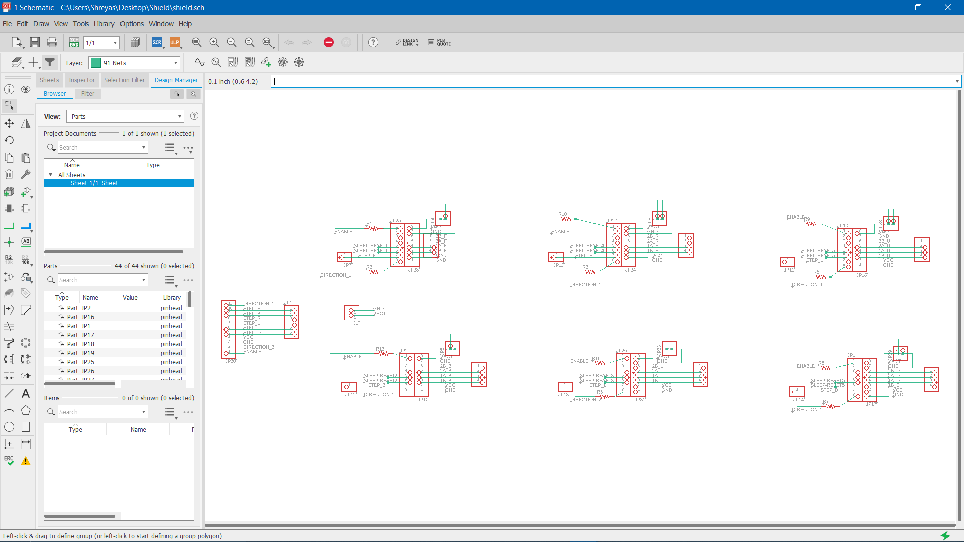
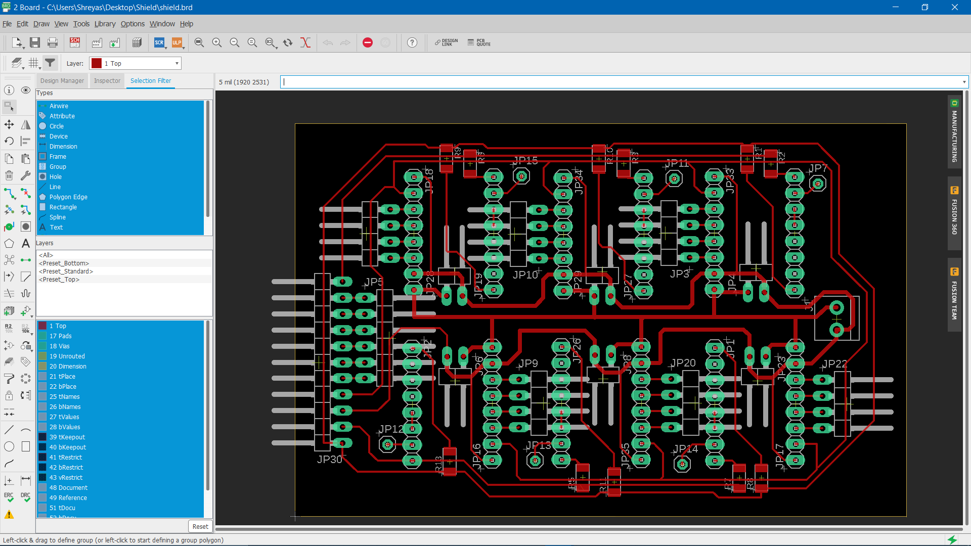
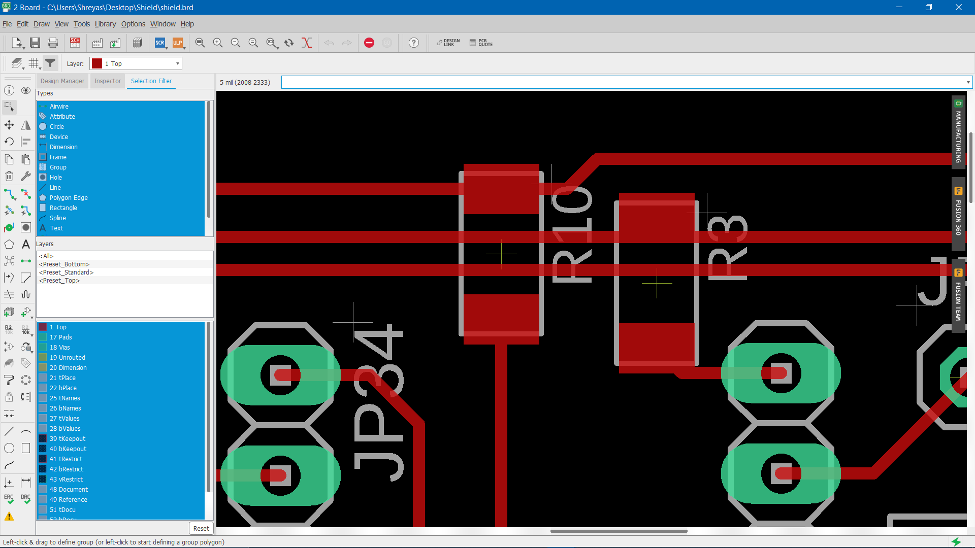
Use these edition Eagle files for the shield. Generate the toolpath according to the machine you are using, and mill it. Solder all the pin headers, and do the jumper wires last. Keep inserting drivers to check that size is maintained, and that you dont solder the pinheader at an angle, but remember to remove the driver once you start soldering, otherwise you might destroy it from the heat.
(Driver Schematic)
(Driver Board Layout)
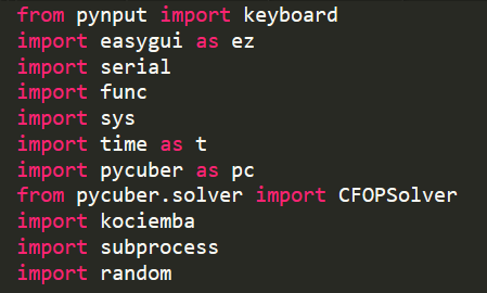
Install these python modules on your PC:
Upload this to the Arduino using the official IDE. I have included the code with the pin number for the Arduino Mega, instead of the Rupino, since you might not be able to make your own Arduino.
(Upload to Arduino)
Then, run this program in your PC's terminal/command prompt to open the GUI:
(Run in CMD/Terminal)
If all your connections are ok, (refer to the code for the connections to the pin on the microcontroller board and the driver board) your motors should be moving. Test the scramble, and then solve.
If it jams up, try adding some lubrication to the cube with a syringe. Also, make sure that the tension on your cube is the factory setting. I had a nightmare involving multiple cycles of tensioning, then loosening, then tensioning again, in which case I had to print multiple replacement connectors since they broke when taking them out. The factory tension might seem loose, but once its in the structure, it adjusts to the optimal requirement.
And there you have it! You have a working Rubik's Cube Solving Robot!