Embedded Programming
Tasks for this week:
- Group- Compare the performance and development workflows for other architectures.
- Read a microcontroller data sheet.
- Program your board to do something, using different programming languages and programming environments.
Part 1- Group Assignment
Due to COVID-19, our main lab was closed. Therefore, we were unable to complete this week's group assignment.
This page will be updated soon.
Part 2- Reading the ATtiny44A Data Sheet
One of our individual tasks this week is to read the Microcontroller Data Sheet for the MCU we used in the Electronics Design and Production weeks. Datasheet is a document provided by the manufacturer, that summarizes the performance and other technical characteristics of a product in details that allows us to understand the role of the component in the overall system. The microcontroller I have used so far is the ATtiny44A, a 8-bit RISC microcontroller. The data sheet I read can be found here.
After my regional review, it was recommended that the best method of reading the datasheet is reading the datasheet like a dictionary, by referring to the Contents page and looking at specific features rather than attempting to read the entire document. Throughout the document, there was several terminology that I did not understand, and the task was quite overwhelming overall. Nevertheless, it is a highly important document, and understanding data sheets is also an important skill.
The main features of the ATtiny44 include:- 256 Bytes of Programmable EEPROM
- 4K Bytes of Flash Program Memory
- 256 bytes SRAM
- 12 programmable I/O (Input/Output) Lines
- Operating Voltage 1.8-5.5V
- One 8-bit and one 16-bit Timer/Counter with Two PWM Channels
- 10-bit ADC (Analogue-Digital Converter)
- Based on the AVR enhanced RISC architecture, which is based on the Harvard architecture.
- On-chip Debug System
- On-chip Temperature Sensor
- Standby and Power-Down Modes
- Internal Calibrated Oscillator
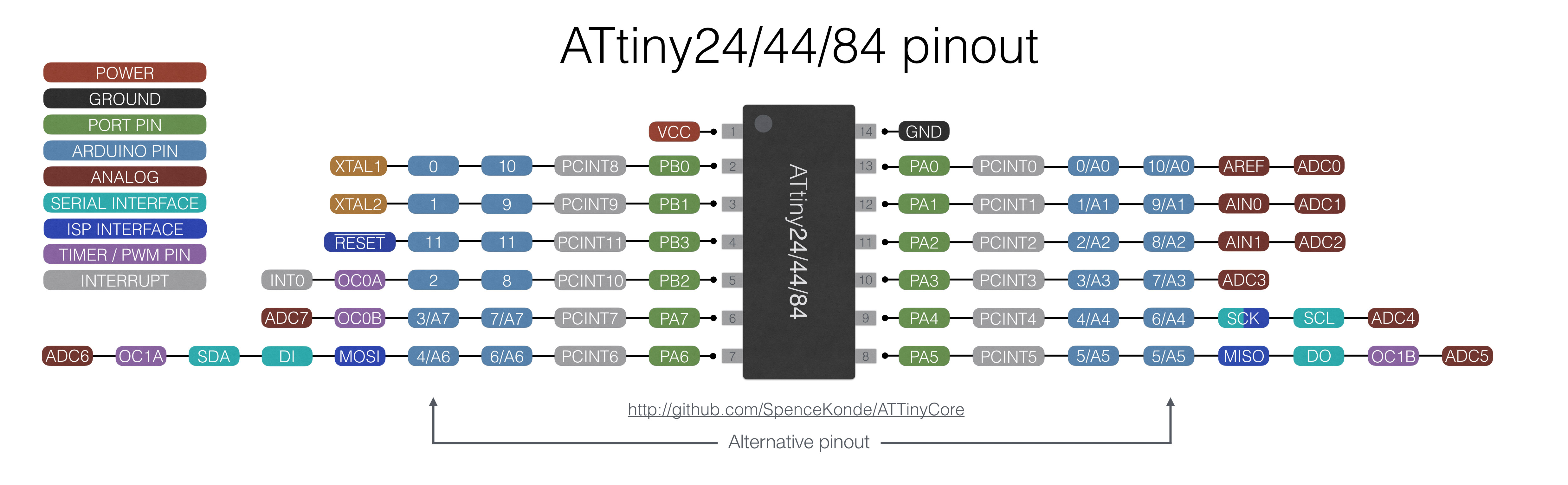
Finally, one of the most useful parts of the datasheet was the Pin layout description.
 Referring to the image above, Pin 1 is the VCC, which is the power supply pin to power the microcontroller, and Pin 14 is the Ground pin (GND). B Ports, PB0 to PB3, are 4-bit bi-directional input/output ports with reset capability. A Ports, PA0 to PA7 are 8-bit bi-directional input/output ports with internal pull-up resistors. These ports can alternatively function as analog inputs for ADC (analogue to digital converter) and timer/counter. Each port has its respective designations, for example PB0 and PB1 being the resonator ports (XTAL), and PA5 and PA6 being MISO (master in slave out) and MOSI (master out slave in) respectively.
Part 3- Programming the Board
This task calls for us to program our boards to do something that involves the button input and LED output we added in last week's assignment. One key feature of this assignment calls for us to explore different programming languages and environments.
A programming language is the communication language used in computer programming. A programming environment is the environment where this language is hosted, tested and ran on.
The first thing I wanted to test was the in-built example of the Led Blink code in Arduino IDE (Integrate Development Environment). Before uploading the code, I had to change the LED pin designation, as I was not using the in-built LED of an Arduino board. In my case, the LED was attached to the Pin 7 equivalent, and the button was attached to the Pin 3 equivalent. THe following image shows the correlation between the pins of the ATtiny and the Arduino digital pin equivalent. It is very important to refer to, as the wrong port designation for the input and output devices would result in the code not working.
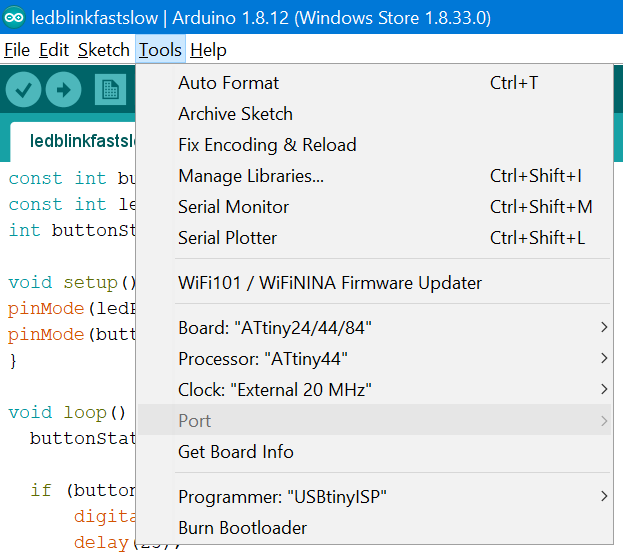
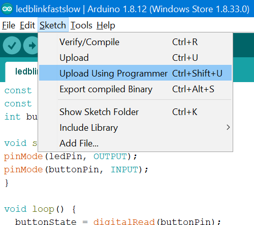
The next step was to uploading the code. Before doing so, there are a few settings to be configured in the IDE. Under Tools >> Board, the ATtiny24/44/84 board option must be selected. Then, the Attiny44 processor must be selected. In the Clock selection, the 20MHz frequency must be specified. Finally, The Programmer should be seleected as the USBtinyISP. When uploading the sketch, we cannot use the direct upload button; afteer the code is verified, under the Sketch menu, the code can be uploaded using the Upload Using Programmer (Ctrl+Shift+U). Later, I found out that after a code has been uploaded in this manner, the standard upload button changes from default to the specified programmer output.
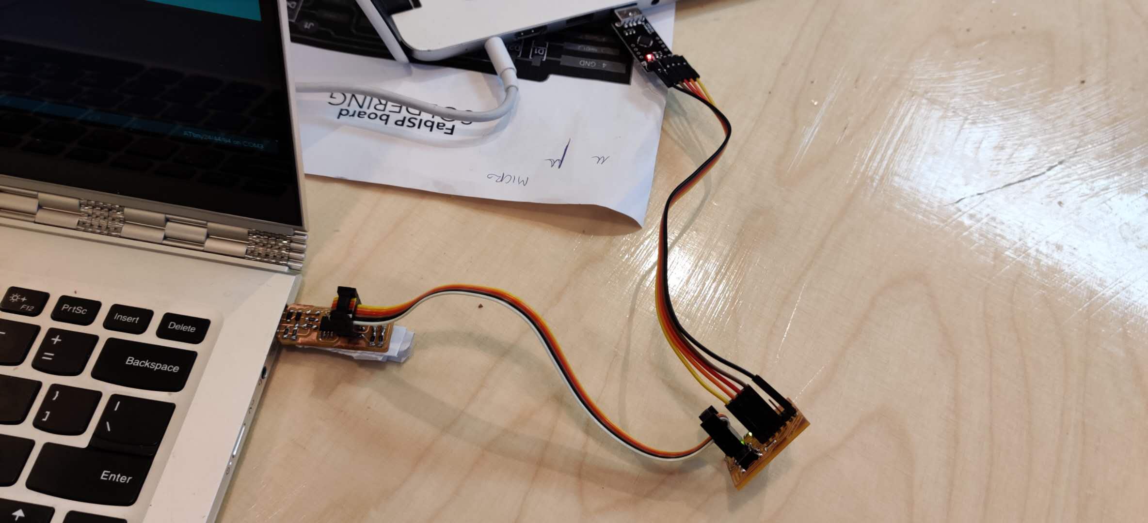
After uploading this code, my LED successfully starting blinking. However, what I noticed was that the LED was blinking at approximately 8 second intervals, whilst the input code had only 1 second. I figured out that this was an issue with the '.make' fuses files provided to us, where the option to 'divide the clock by 8' was probably not selected. The solution for this would be to re-make the fuses with this option selected, or to divide all the times by 8 to achieve the intended time. After changing the values, I connected the computer to the board using my FabISP, then connected the board to a power source using the FTDI cable. When the code was uploaded, I disconnected the FabISP and the FTDI power connection remained. This blinking code worked succesfully.
After I tested that an existing code would work, I began modifying that code to change the rate at which the LED would blink when the button is pressed. This involved defining what Pin the button was on, defining the input and output pinModes, and using the If, Else functions in a loop to determine the output for when the Button position is high or low.
------
LED Blink Rate Change Code
const int buttonPin = 3;
const int ledPin = 7;
int buttonState = 0;

void setup() {
pinMode(ledPin, OUTPUT);
pinMode(buttonPin, INPUT);
}

void loop() {
  buttonState = digitalRead(buttonPin);

  if (buttonState == HIGH) {
      digitalWrite(ledPin, HIGH);
      delay(25);
      digitalWrite(ledPin, LOW);
      delay(25);
  } else {
      digitalWrite(ledPin, HIGH);
      delay(12.5);
      digitalWrite(ledPin, LOW);
      delay(12.5);
  }
  }
------
The code was successfully uploaded, and here is the result:
Then, I decided to switch to the Programino IDE, an environment which is quite similar to Arduino IDE, which has a hardware viewer, debugging assistance and custom syntax highlighting. I used the 14-day free trial for this more professional alternative, but I would say that I prefer the Arduino IDE comparatively.
I also decided to try another programing language. I don't have a great understanding of programming, and learning an entirely new language is almost impossible within the time constraints of a week. I chose to learn C, a highly important language as it has uses in many applications. I watched several tutorial videos on YouTube, and read through previous student's documentations of using C. I saved this file as 'ledblink.c', and using the existing make files provided to us, I opened GitBash, and ran the make and the make program-usbtiny commands. The code was successfully uploaded on the first attempt, and the LED started blinking.
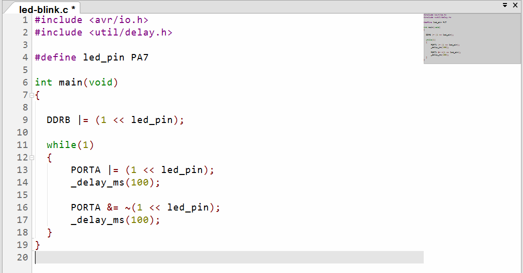

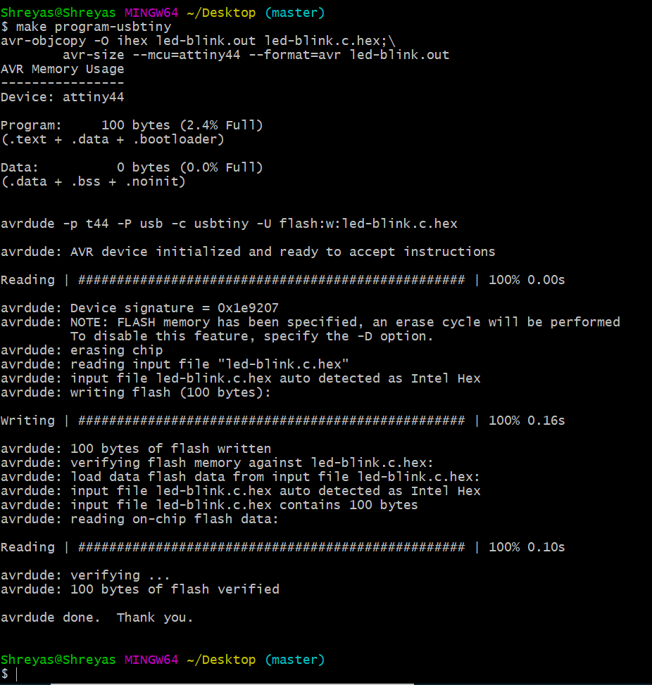 After all this research and learning, I am still not really confident with the language, but I understood the basics of it, which allowed me to run this simple LED Blink code made in C language.
Although this is the most basic possible thing to code, I made it with a language that I didn't know only a week ago, and that is a good achievement for me.
After all this research and learning, I am still not really confident with the language, but I understood the basics of it, which allowed me to run this simple LED Blink code made in C language.
Although this is the most basic possible thing to code, I made it with a language that I didn't know only a week ago, and that is a good achievement for me.
Finally, I was experimenting with other codes that I could run on my board. During my searches, I came across this documentation from 2017 by Thrasyvoulos Karydis of an LED that blinks in Morse Code, and sends the SOS signal. However, on his website, I could not find the code for running something like this. So, what I did wass to find this code elsewhere, and I found several examples on YouTube and Instructables. These versions improved the concept by forming a serial communication between the computer and the board to communicate all the letters of the alphabet in morse code, meaning that anything could be communicated. When I downloaded these codes, I did the necessary modifications to the pin numbers and the time values, and attempted to upload this to the board. Here is where I encountered an error in this assignment. These codes were simply too big to be uploaded onto the ATtiny44 microcontroller. However, I really wanted to get this working, so what I decided to do was use the LED blink code that I had modified, and the Morse LED codes as references to create my own code in Arduino IDE. When the button is in high position, the LED is constantly on. When the button is pressed, the LED does 3 quick flashes then 3 long strobes, then 3 quick flashes, which represents the Morse method of communicating SOS. Between every SOS pattern is a 2 second delay. When you release the button, the LED returns to being always on.
------
LED Morse Code SOS Signal Code
const int ledPin = 7;
const int buttonPin = 3;
int s = 10; // 0.3 second delay for 'S' letter
int o = 75; // 1.5 second delay for 'O' letter
int pause = 20; // 0.4 second delay between letters
int buttonState = 0;

void setup() {
  pinMode(ledPin, OUTPUT);
  pinMode(buttonPin, INPUT);
}
void character(int speed, int pause) {
  for (int i = 1; i <= 3; i++) {
    if (digitalRead(buttonPin) == LOW) {
      digitalWrite(ledPin, HIGH);
      delay(speed);
      digitalWrite(ledPin, LOW);
      delay(20);
    }
    else {
      digitalWrite(ledPin, HIGH);
    }
    delay(pause); //delay between letters
  }
}
void loop() {
  character(s, pause);
  character(o, pause);
  character(s, pause);
  delay(200); //delay after each SOS
}
Click here to download the LED Blink Fast/Slow Code
Click here to download the LED Blink C Code
Click here to download the LED Morse Code SOS Code