Computer Controlled Machining
Tasks for this week:
- Group- test runout, alignment, speeds, feeds, and toolpaths for your machine.
- Make (design+mill+assemble) something big.
Part 1- Group Assignment
Link to Group Assignment
Part 2- Design
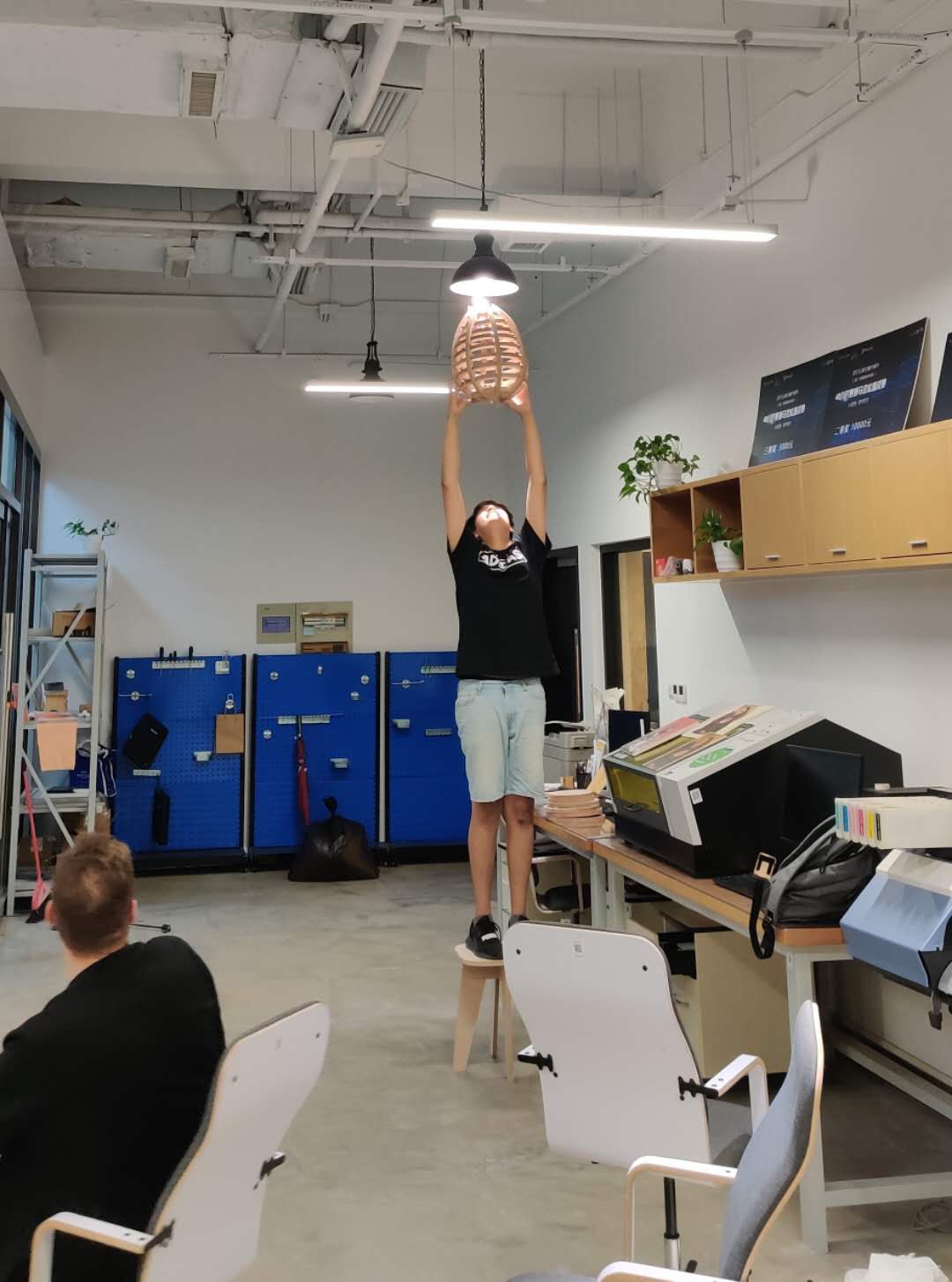
This week was initially difficult in terms of deciding what to make, especially in terms of making something feasible in terms of the amount of material we are given. I circled around from making a desk, a chair, a shelf, a desk organizer, a skateboard deck. Some of these were simply not possible to produced from one sheet, and some I couldn't design. I eventually decided to make a large lamp, which I will combine with an exercise from the Output Devices and Interface and Application Programming weeks to make a lamp whose color can be changed with an app.
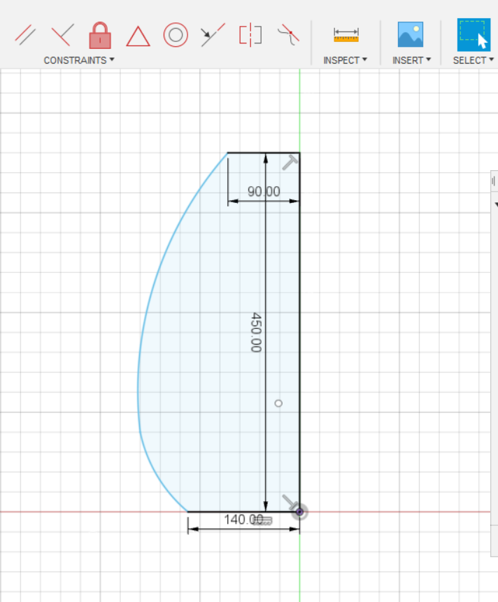
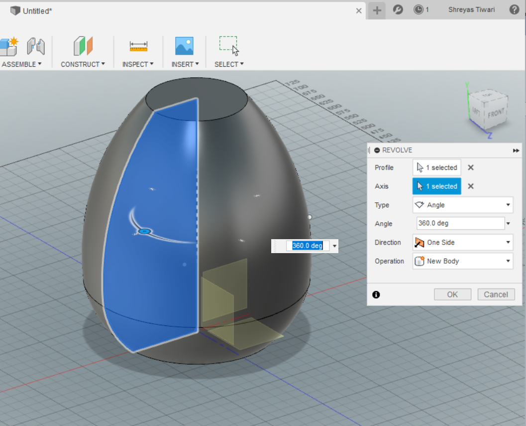
I designed the shape using the Revolve Tool in Fusion 360, then made the final shape using Slicer For Fusion360. Slicer is a great software in terms of creating designs specifically for machining; for example, you can add dogbones to all joints using the click of a single button.
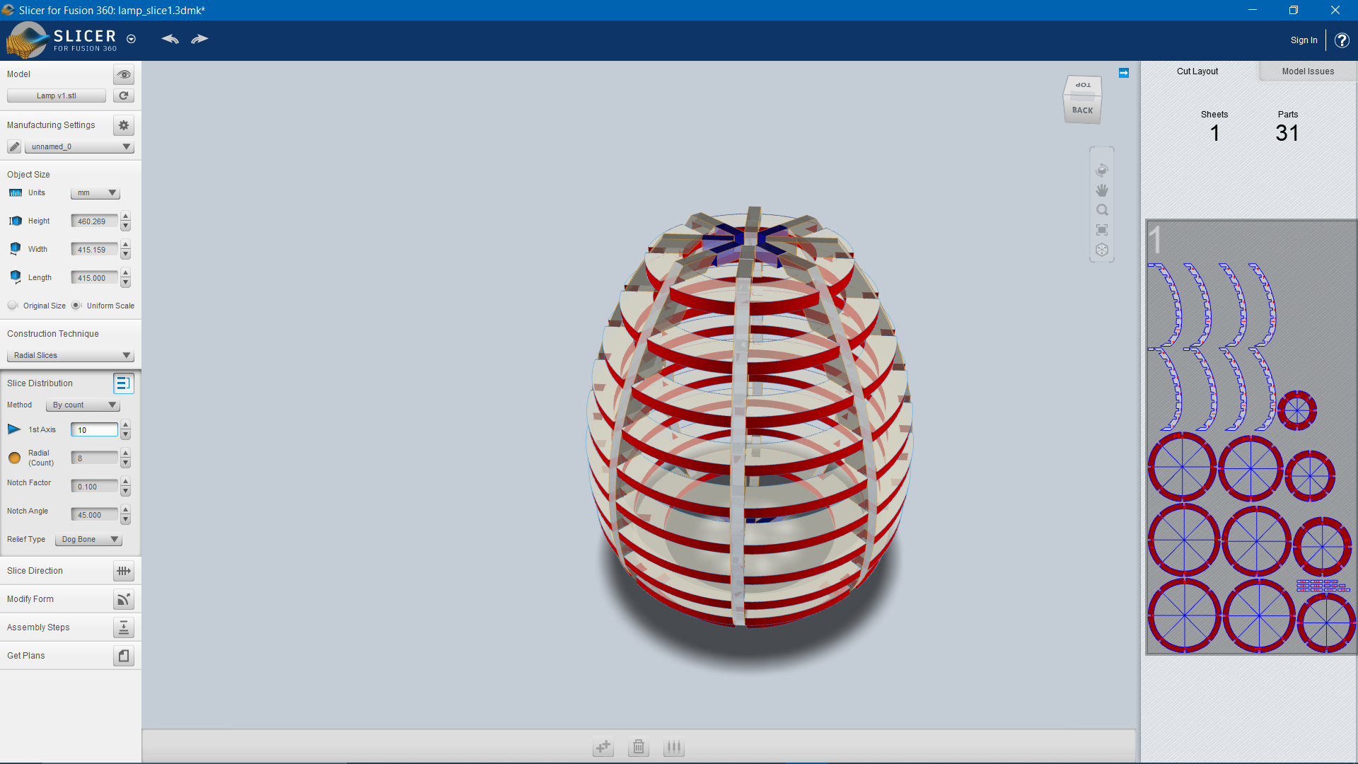
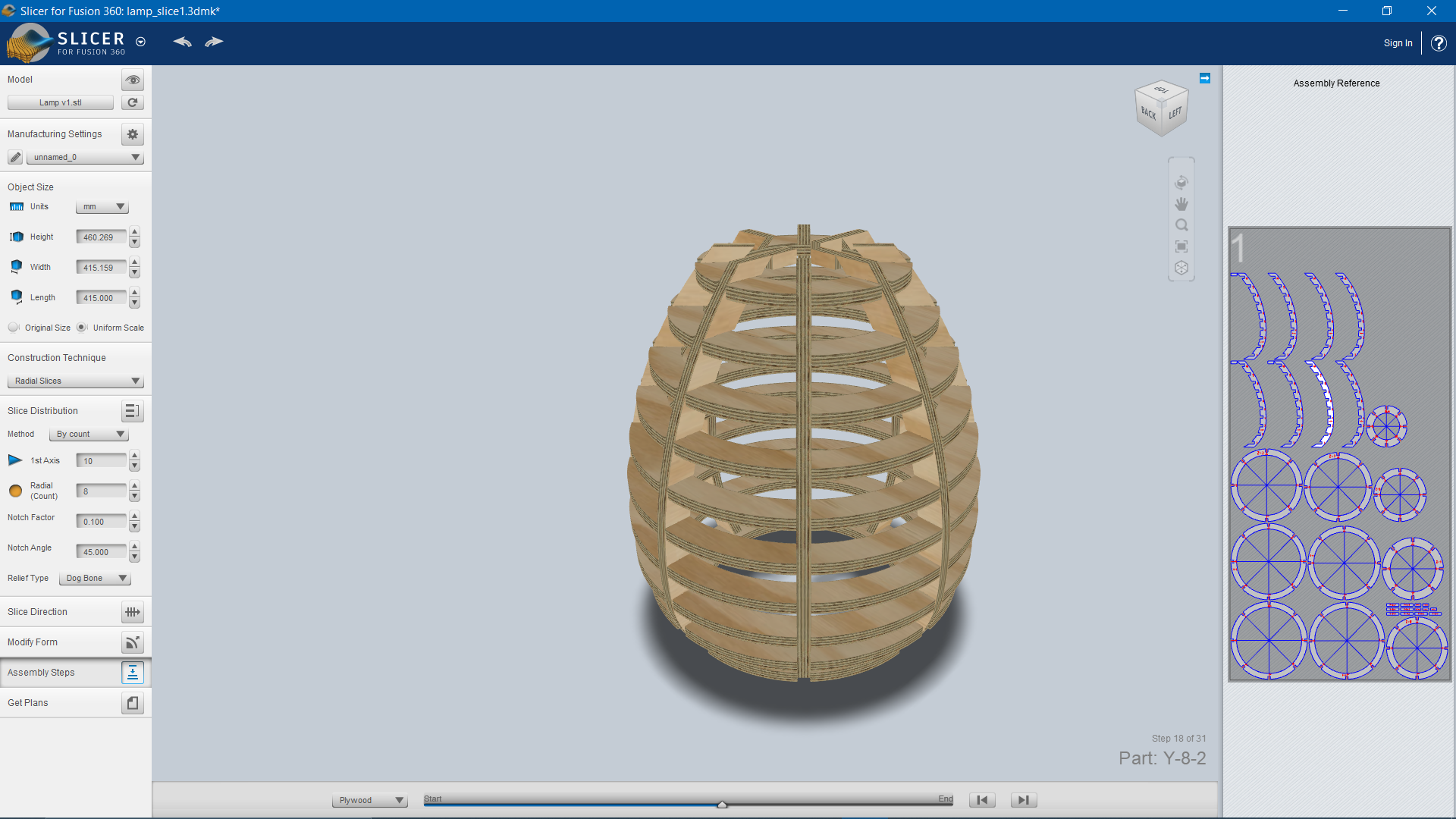
I then exported the file as a .STL, then opened it in Slicer. There, I specified the size and thickness of my material, then chose the Radial Slices. I played around with the number of radials and the number of vertical interlocked slices, until I reached a design that looked good and had less than 20 parts (8 and 10 respectively).
 The issue I was having here is that some of the side pieces were split into 2 pieces, so to fix this, I opened the .dxf file into Fusion 360 and tried to use the Combine tool to fix this error. The problem is that Fusion cannot handle even the slightest intensive work, and would either lag, or commonly freeze, and then randomly close. After getting frustrated with the software, I switched over to Rhino. There, I closed off the lines, and then copied that piece 8 times and nested them efficiently. It was so well packed that I ended up only requiring half of the sheet.
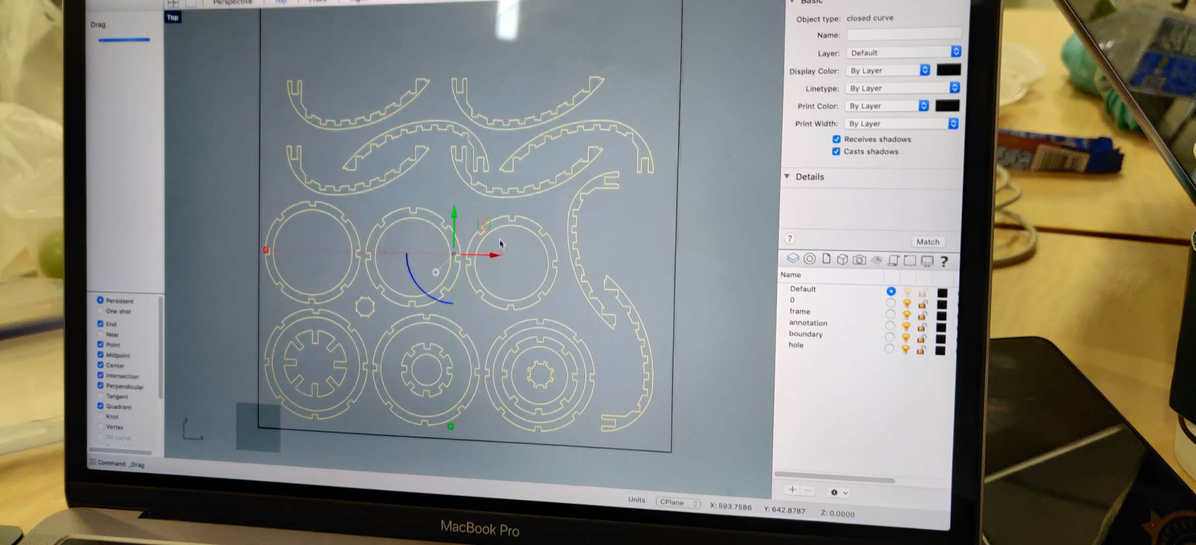
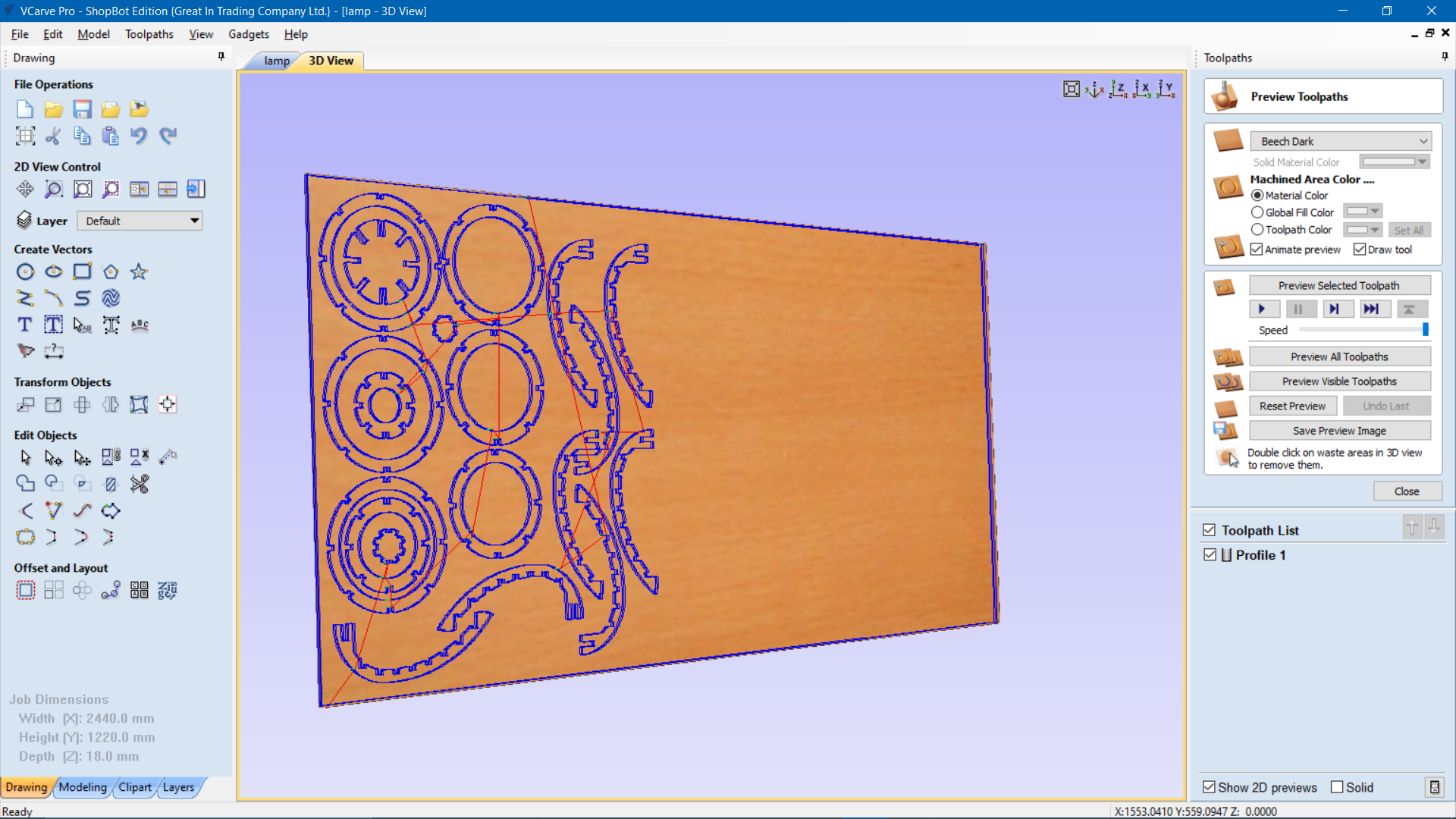
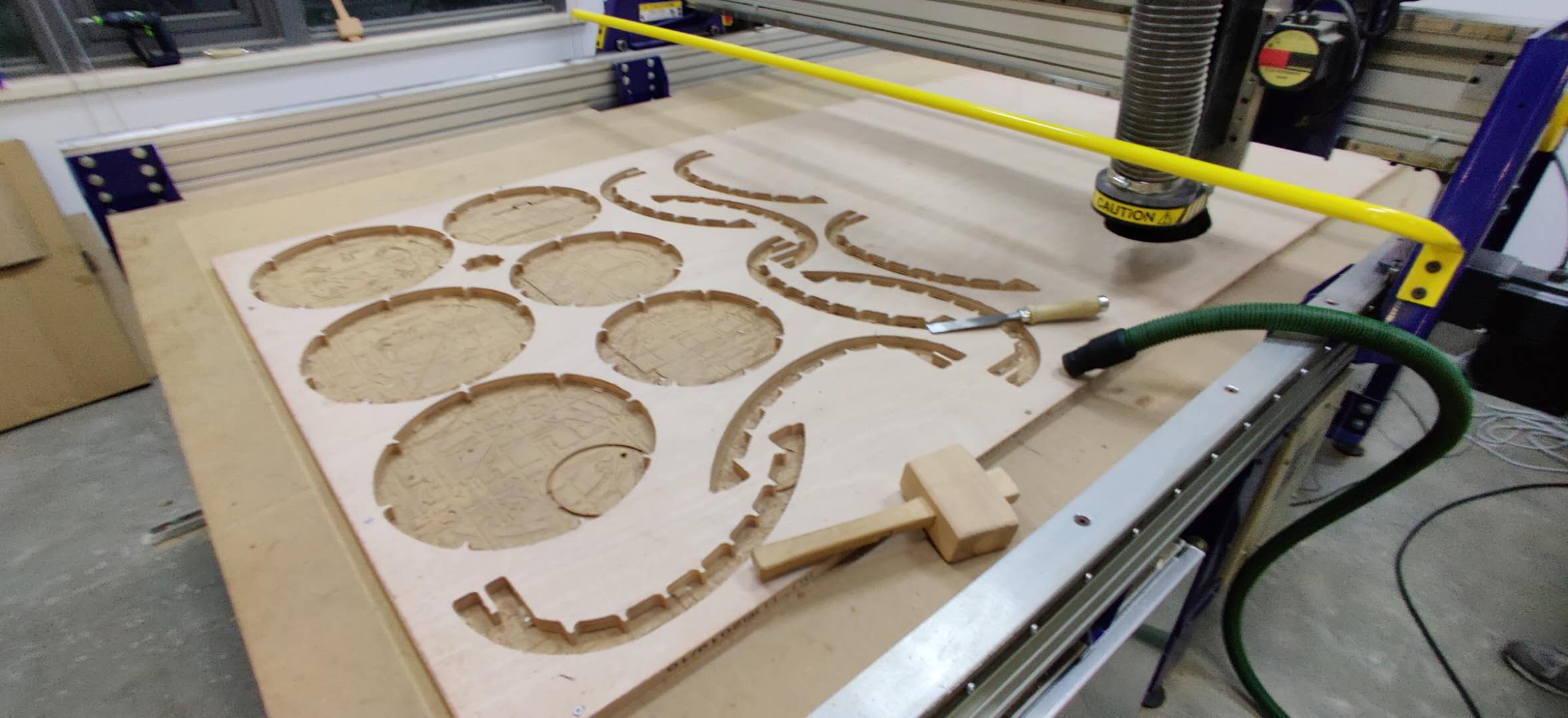
The next step was to generate toolpaths using VCarve Pro. In my case, I had to do the single task of downcut, which is why this machining process only took 40 minutes on the Shopbot.
Steps in VCarve:
- Create a new file, specify the stock material size as 2440 mm X 1220 mm, and specify the thickness as 14 mm, with Z zero being at the top of the surface. The 1220 mm side is the x-axis, and the 2440 mm side is the y-axis on the shopbot. Error!- Somehow, the wrong sheet was delivered, so now we have to work with 18 mm thick wood. I went back to slicer, regenerated the dxf file, reopened in Rhino and redesigned the piece again, before opening VCarve and doing this process again.
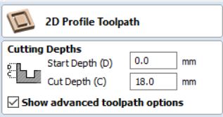
- In the toolpaths area, I selected the 2D profile toolpath option. Specified cut depth at 18 mm.
- Select the endmill. I only had to use the 1/4" up-cut (57-910) endmill, changed the spindle speed to 18000 rpm, and the feed rate to 3.6 inches/sec. Click Apply to make changes.
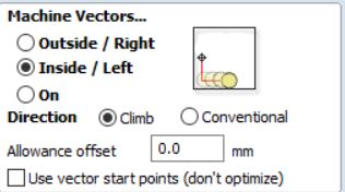
- Conventionally, you are supposed to select the Machine Vectors as Outside/Right, with the direction as Climb. However, since I had some smaller components inside larger components, the toolpath preview was incorrect. This was fixed by selecting Inside/Left.
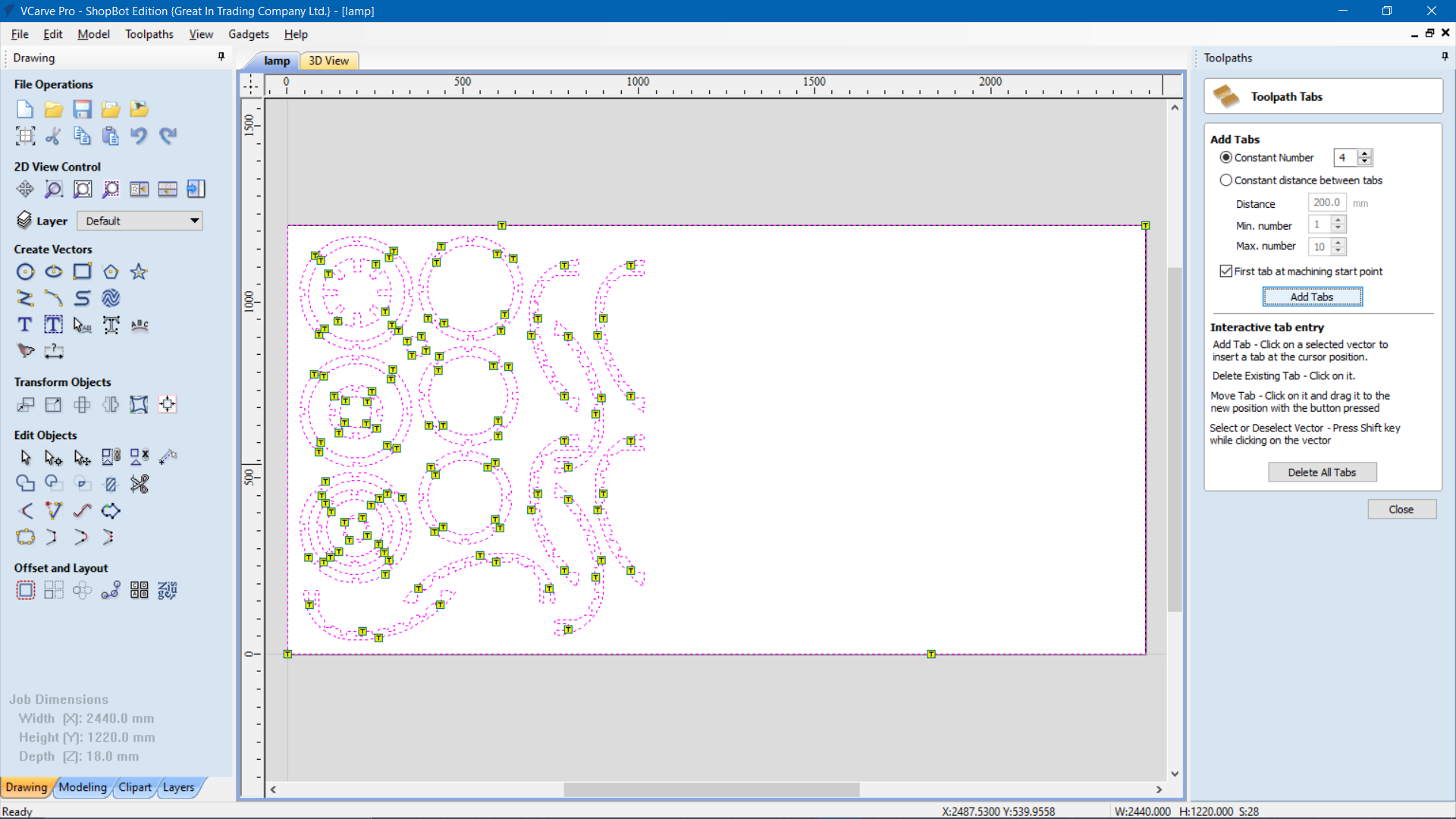
- Add 3-4 tabs for each component. Make sure its not on an edge or curved surface. (Left-click drag to move the position of tabs)
-
Calculate toolpaths. View them in 3D perspective. (In the toolpaths, the 1220 mm side is the x-axis, and the 2440 mm side is the y-axis on the shopbot. From my arangement of all the pieces, I did not need to use much of the y-axis length of the sheet, so the remaining half was saved to be used by someone else.)
Save profile as Profile 1. Export as a .crv file.

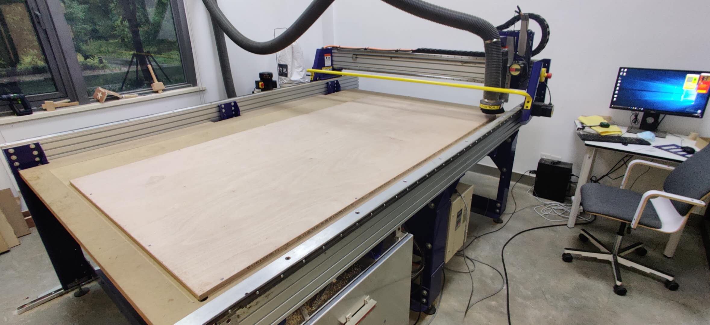
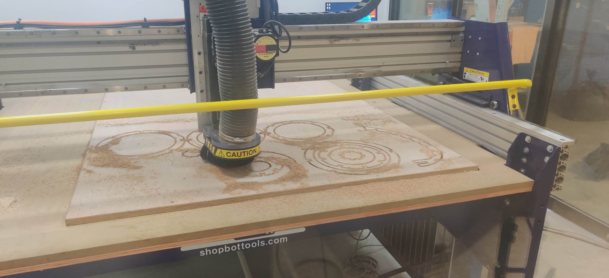
I then opened up the .crv file onto the PC for the shopbot, and re-evaluated the toolpath. Once I had confirmed that the toolpath's settings match, I exported the file as .sbp, then I proceeded with preparations for machining. I screwed in the board to the sacrificial layer, but I only screwed on three sides since the milling only requires half of the sheet. The exact procedures for setting up the Shopbot are documented in the group assignment above, but the most important key points were to ensure that: the endmill was secured tightly, the bed was completely flat, there are 2 people in the area, the emergency stop switch is within reach, people are out of the way of the machine, protective gear for skin, face and ears are worn, hand is on the mouse ready to pause in an emergency. Then, after a piece was completely milled, I inspected it and it was cutting well. After this, I let the machine do its job.
Part 3- Assembly
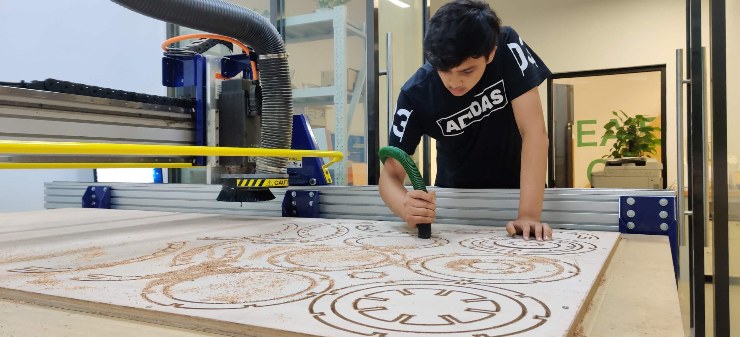
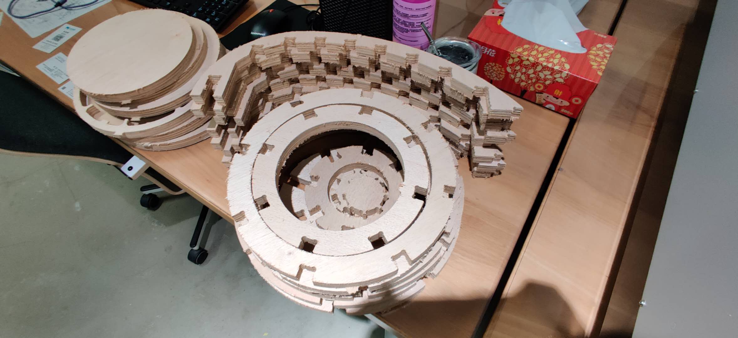
The milling process was successful. I used the vaccuum to clean off the sawdust, then I proceeded with cutting the tabs using a chisel and a mallet. It took quite a while to do this, since there were a lot of parts with 4 tabs each. Once the parts were taken off, some of the edges were really rough. The finish would have been much better if I would have used a downcut endmill to cut partial depth, then use the upcut endmill to finish the job. I used a handheld sanding machine to clean the frayed edges, but it still isn't smooth enough for a good fit.
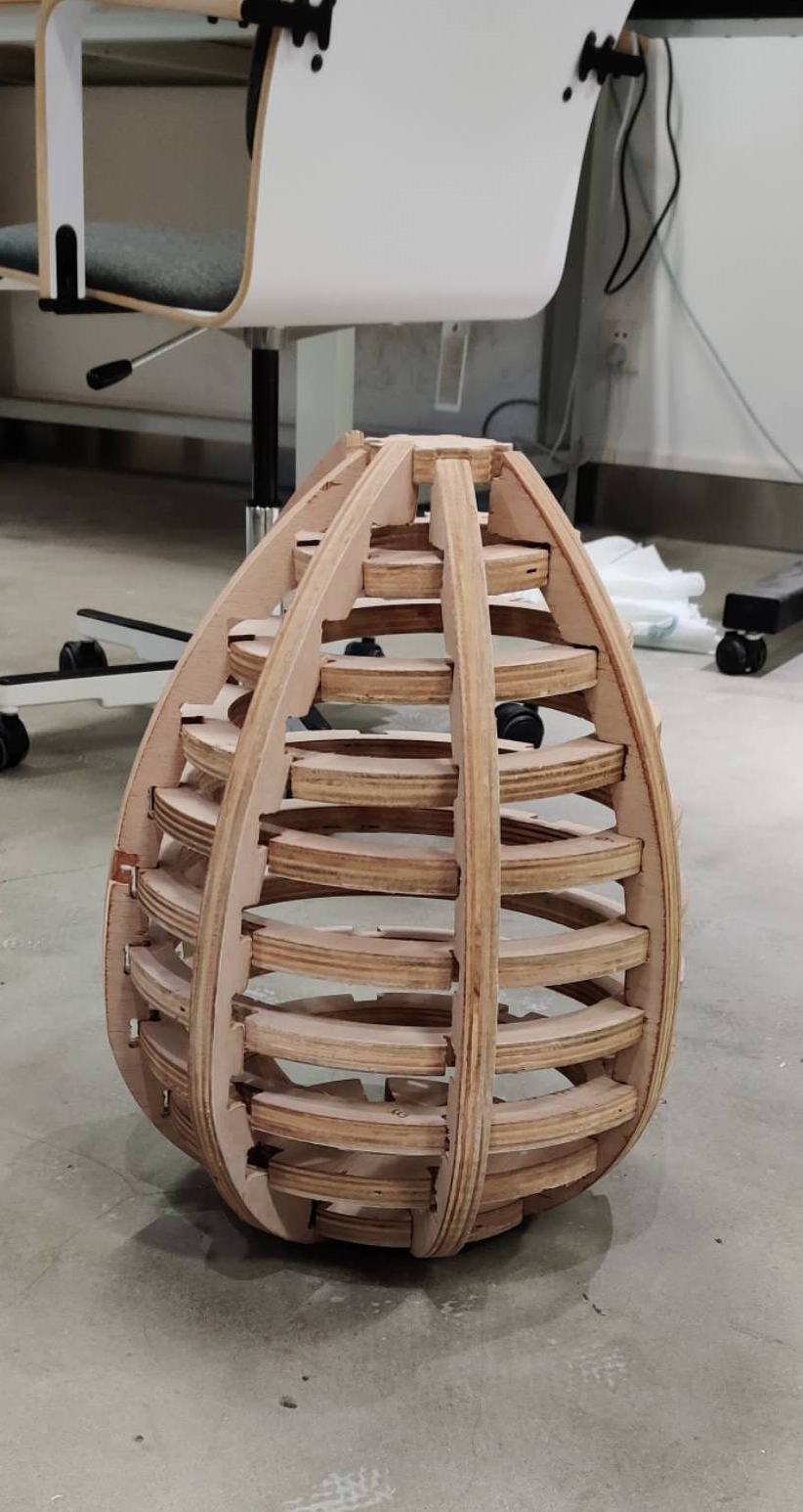
I managed to assemble the structure, but I haven't installed the LEDs yet. If I have time later, after the Final Project, I might be able to sand it properly, apply a finish and assemble with the LED and Arduino circuit. For now, here are some hero shots, as well as a makeshift proof of concept.
Design files here:
Lamp's CRV file
Lamp's Slicer File