Computer Controlled Cutting
Tasks for this week:
- Group- characterize your lasercutter's focus, power, speed, rate, kerf, and joint clearance.
- Design, lasercut, and document a parametric press-fit construction kit, which can be assembled in multiple ways.
- Cut something on a vinyl cutter.
Part 1- Group Assignment
Link to Group Assignment
This documentation is related to the use of the laser cutter, what settings we used to cut our designs, including speed, power, the thickness of the material, as well as calculating and adjusting the size to compensate for kerf.
Part 2- Vinyl Cutter
This week is also dedicated to learning how to use the vinyl cutter. I have already designed a logo in the previous week, when I was exploring 2D CAD tools. I exported the file in the .svg format (attached below), and I plan on using this sticker on my laptop and on my final project as well!
Logo.svg File
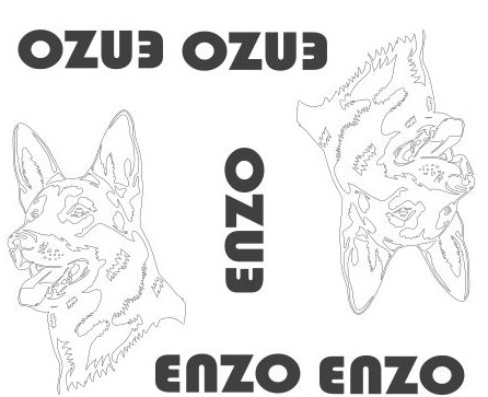
Another idea I had to make on the vinyl cutter was a sticker of my German Shepherd Dog, Enzo, to be used on his frisbee and food bowl. I attempted to design my own file, but it was quite complicated. Therefore, I used this design that I found online. I opened the .dxf file in Inkscape, where I added the 'ENZO' label, duplicated it, and oriented it in the most efficient format. The final orientation looks like this, ready for vinyl cutting:
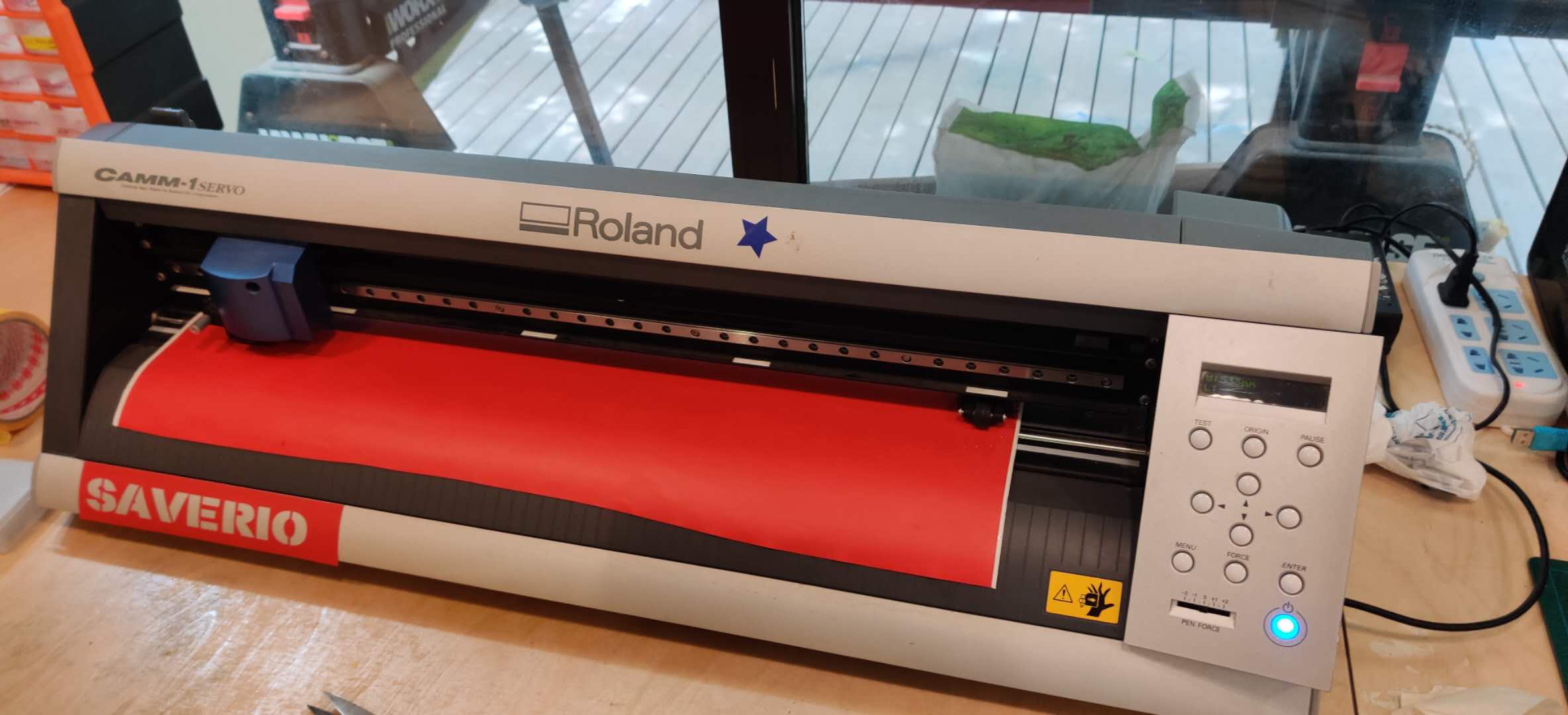
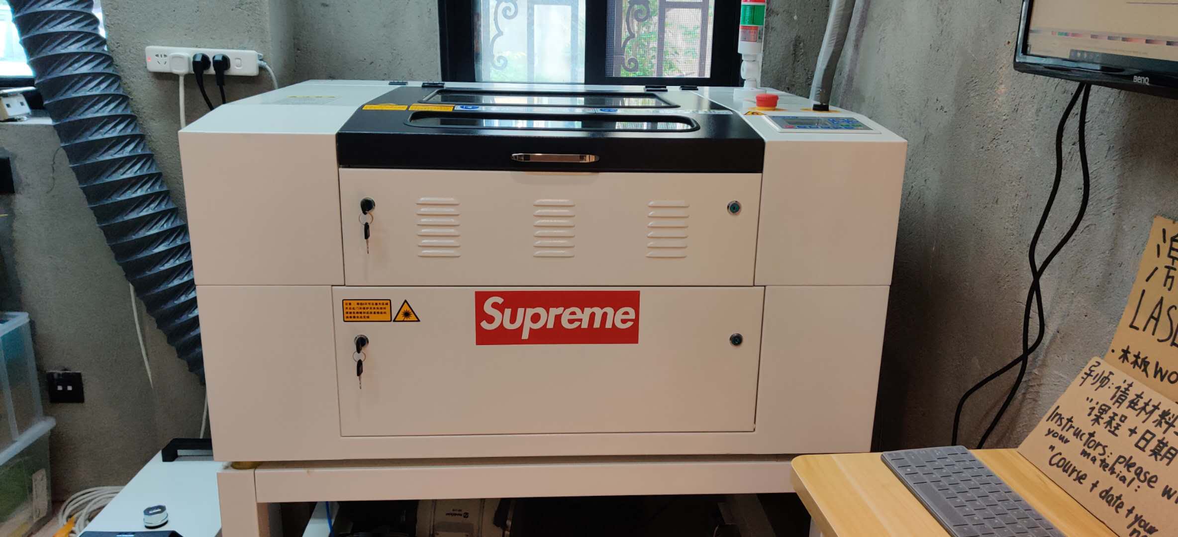
Update: The details for cutting this on the vinyl cutter are too complicated, so I changed my design. I took an image of the Supreme logo from the web (since we only had red vinyl). It is important to make sure the two pinch rollers are within the white space, otherwise the cutter will display error message saying "bad position". Then clip the paper tight so the position stays precise while cutting. I imported the image into Roland CutStudio, and I placed my graphic within the canvas area, and I hit the output button. I then used tape to peel off the cut stickers from the vinyl, before transferring the sticker. My instructor allowed me to place the sticker on our laser cutter, and now that machine is worth more than the cost of a FabLab ;)
Part 3- Laser Cutting
Even though I can not actually produce and test my parametric construction kit, I hope that my CAD designs of modules will be able to convey what the end result would have looked like. Later, when we have access to the lab again, I can produce them and update this site with documentation.
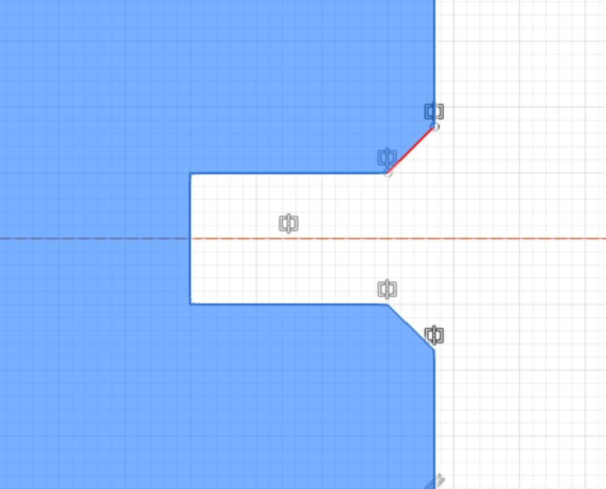
Error! - I was struggling to design the joints in the parametric design, because they kept on losing symmetry. Thankfully, with help from my instructor, I learnt a technique that allows joints to be parametrically altered whilst keeping symmetry.
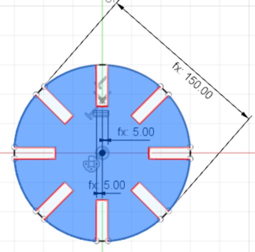
Another thing I decided to do was to design as many shapes as possible, which allowed me to practice more parametric designing. The first thing I did was design a circle with 8 possible joints. The steps I took are as follows. Draw a circle, and add a parameter called 'Diameter' with the value set to 150mm. Also, add a parameter called 'Thickness', to represent the width of the joint. Draw a joint, and remember to start from the midpoint- To ensure that you use the midpoint, draw construction lines. To change the size of the joint whilst maintaining symmetry on either side, it is important to start from the middle to the end of the corner, and with the Dimension tool, set the width at 'Thickness/2'. Repeat for the other end. This ensures that the symmetry is maintained, and that the final thickness of the joint is exactly as required in the original parameter. Finally, I used the Circular Pattern tool to duplicate this joint 8 times symmetrically. It is important to note that any changes in the parametric values will be reflected in the duplicated models as well. The final outcome looks like this:
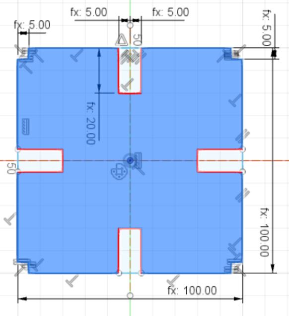
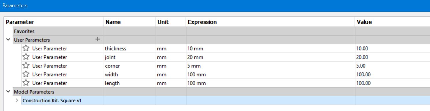
Next, I made a square with the same steps as above, only with 4 joints produced with the Circular Pattern tool. The only difference this time was that I attempted to cut off the corners to give a better overall design, but the dimensions of the corner kept changing. As a result, I used the 'Equal' contraint to make all sides of the corner the same size, whilst maintaining the size of the overall structure. This is shown as follows.
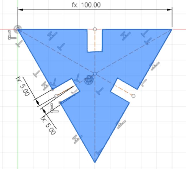
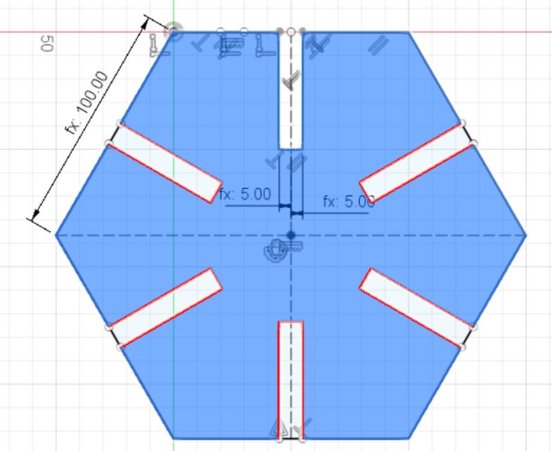
 Similarly, a parametric construction design of hexagons and triangles was created with the same method as shown above.
We were able to access a lab and complete this works assignment this week. 25/2/2020
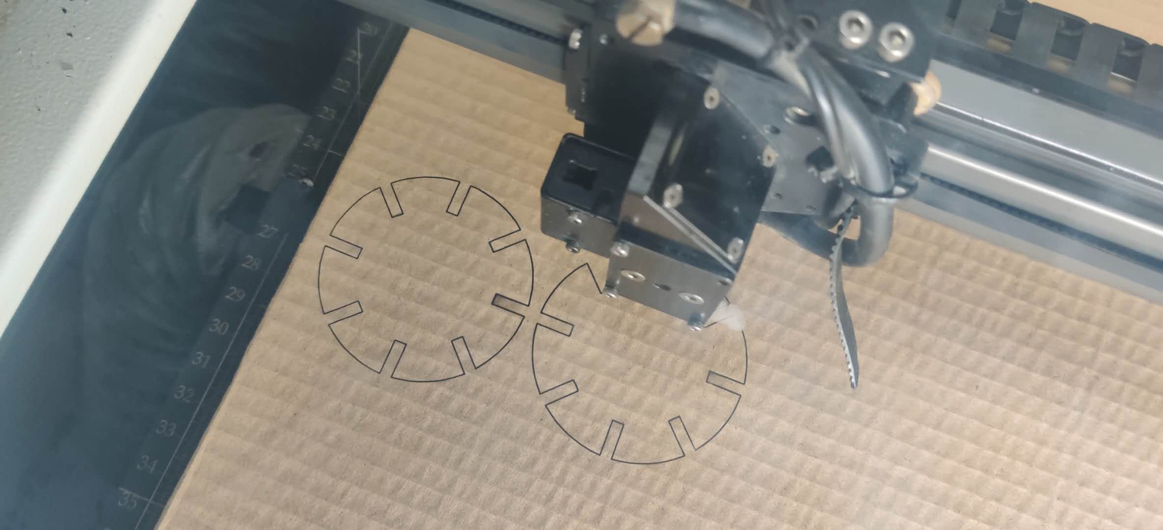
After completing the group assignment, I started the individual assignment of creating a parametric press-fit construction kit. I went back to my design to change the parameters in accordance with the joint clearance testing we had done as a group for the 3mm cardboard. I changed the sizes of the joints, then exported it as a .dxf file from Fusion 360. Error! - When attempting to open the files in Inkscape, all I could see was a single line instead of the shape that I had exported. After evaluating my CAD file, I figured out that my entire sketch was drawn on the wrong axis. My sketch involved the Z-axis, hence the straight line when llooked from the Z perspective. I tried many things to switch the plane on which the sketch was drawn, but to no success. Therefore, I had to redraw the parametic design, this time ensuring that I was using the X- and Y-axis. With the design correct, I again exported the file as a .dxf, and opened it in Inkscape. There, I copied the design and arranged it in the most effective layout to minimize waste. With this file, I started printing the triangle and circle pieces.

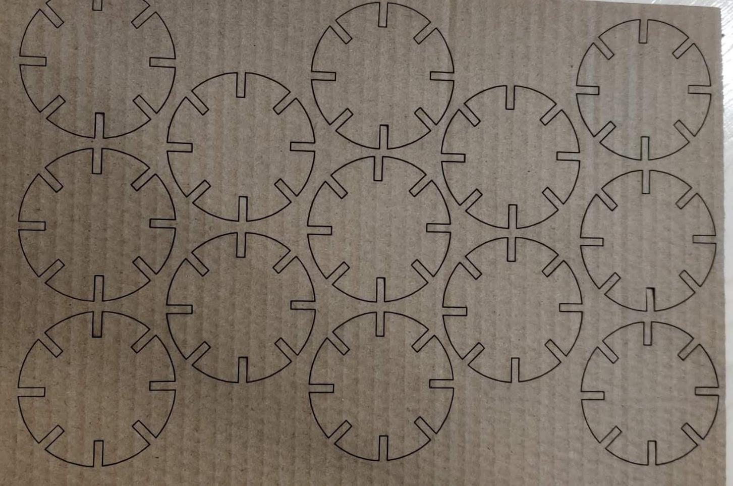
The cutting parameters specified for the job demonstrated above are listed here:
- Speed: 4.0
- Power: 55
- Material Thickness: 3mm
- PPI: 500
I also had to account for kerf compensation, since this laser cutting project is a press-fit construction kit, therefore, it is important that the sizes are accurately calculated, to allow a better fit.
- In the settings listed above, after doing the group assignment, it was determined that the kerf is (3-2.75)/2 = 0.175 mm
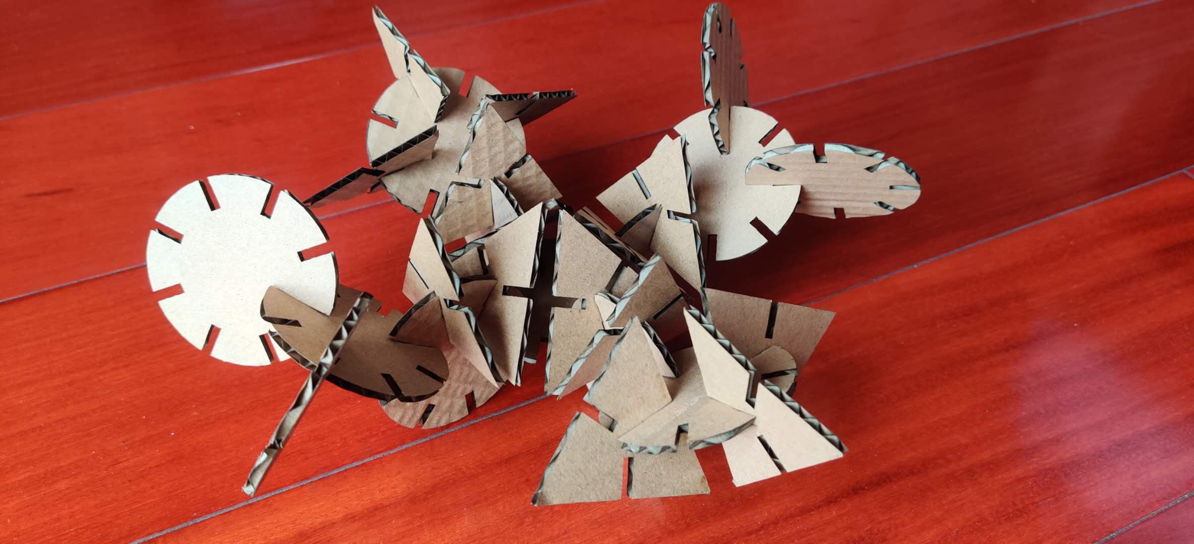
The joints fit well together. But, I could not create any meaningful purpose out of the shape, however, this is a cool design that I made out of the pieces.
After the Regional Review, it was recommended that I should chamfer the edges for a better, more solid press-fit result. Although I could not laser cut the chamfered version, I still designed a chamfer in my design whose shape can be parametrically altered.