Week 3- Computer-Aided Design
Tasks for this week:
- Model (raster, vector, 2D, 3D, render, animate, simulate) a possible final project.
- Compress your images and videos, and post it on your class page.
Part 1- Learning CAD Basics
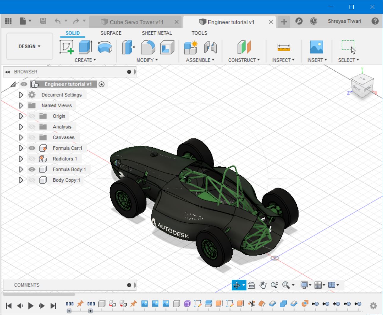
This is going to be my very first attempt at 3D CAD Design. I have always wanted to learn it, and now I finally have the opportunity to do so. I was recommended to start with Fusion 360, and the first thing I did was follow some of their self-paced tutorials. I did the 'Getting Started in Fusion 360' tutorial to get the gist of working with CAD tools, and then I proceeded with 'Fusion 360 for Designers' tutorial. This course is divided into 4 parts, in which I designed a 2-piece carbon fibre Formula SAE car body. Through this course, I will learn how to turn 2D concepts into complex 3D models, modify the form of the structure, work with surfaces, and generate a realistic rendering of the design. Next, I also did the 'Fusion 360 for Engineers' course, which is divided into 3 parts that focus on a Formula SAE car's chassis, mechanical suspension components, as well as validating motion in an assembly, exploring assemblies, animations and drawings and simulation studies. In this week, I have managed to work with 2D design, 3D modelling, Rendering, and Animation. In the future, I plan on continuing with this software, and I will test it's Simulation feature as well.
Part 2- Final Project
The first thing I designed was a logo for my final project. I used Inkscape, which is a powerful 2D Vector tool. I have also never used this software, but a quick search on YouTube for a tutorial was the solution. The software is difficult to initially use, and one of the things that I found challenging was defining the color of the stroke and fill using the color bar at the bottom. Nevertheless, the shortcuts made the entire experience of using the software much more intuitive. The logo I designed portrays a 3D cube, but it is a design that should be easily etched using a laser cutter. The basic shape is quite simple; it is made with 3 squares, with lines offsetting, and some of the lines erased to create the 3D effect. Below it is text that reads 'Rubik's Cubed', which intends to imply that the prototype solves or completes Rubik's puzzle.
Next, I started designing my final project, initially planning to document my work with Windows GameBar Recording. However, for some reason, the start and end of the video was cut, and I was not able to fix it. Also, the files it recorded were massive in size, and no amount of compression would make them small enough to be uploaded onto my repository. It was only after finishing my CAD assignment did I realize that I hadn't taken any photos of the steps in making it. Luckily, Fusion 360 has this feature called 'Timeline', where it captures your design history. With this, I was able to open previous versions of my file.
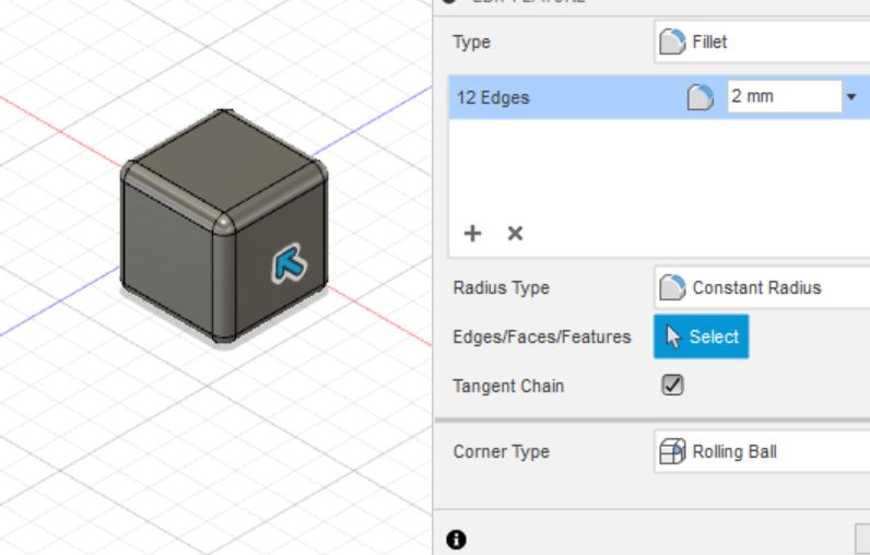
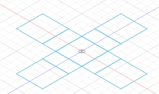
The first thing I modelled was a Rubik's cube to provide reference to the solving machine I will model. Step 1: Sketch a square (19mm*19mm), Extrude it by 19mm, and Fillet the corners by 2mm.
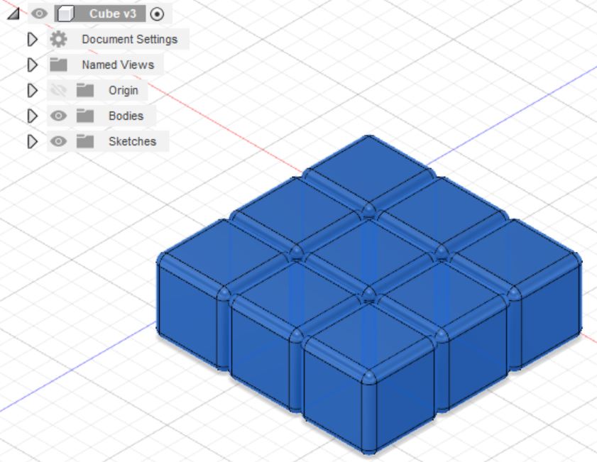
Next, I used the Rectangular Pattern tool to duplicate the cube into 3 cubes, Combined them, then made 3 rows.
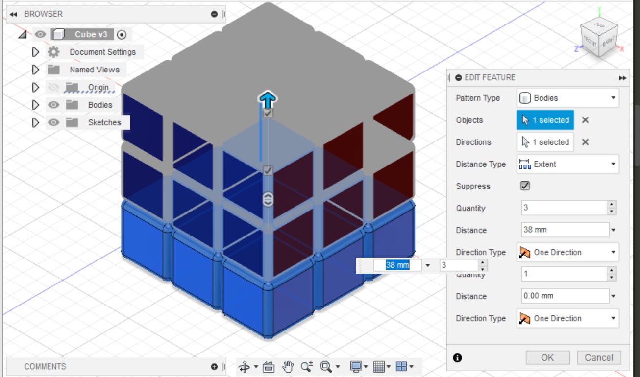
The Rectangular Pattern tool was again used to complete the cube structure.
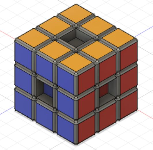
I then selected the Render menu, where I clicked on Appearances, chose the cube's colors and applied them to selected faces.
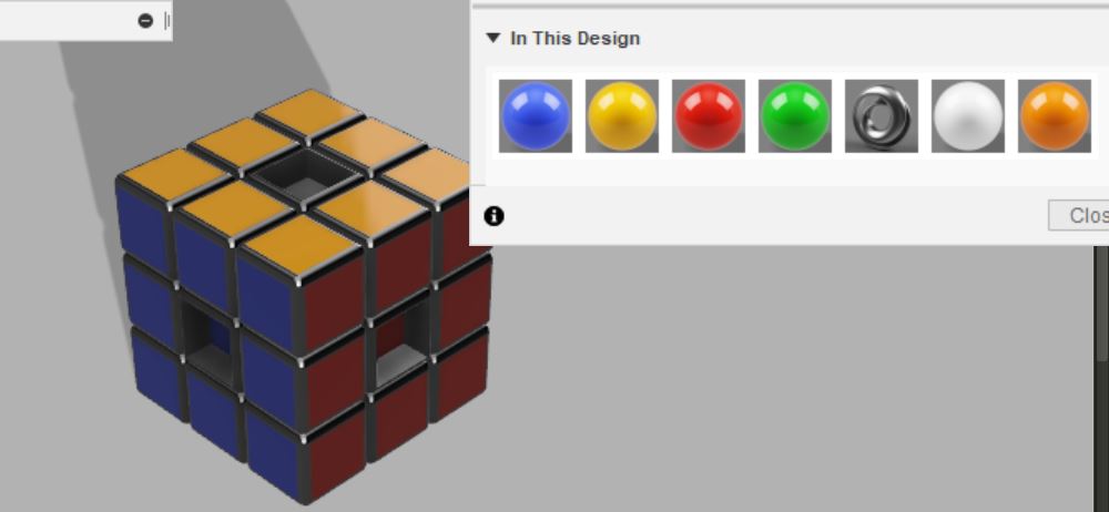 Finally, I negatively extruded all the center caps to represent where the servo motors will mount onto.
 Error!
 After completing the design, my software froze and stopped responding, and Fusion 360 closed. When I restarted the program, I couldn't find my file's latest version! Thankfully, Fusion 360 is a cloud-based software and presented the auto-recovered file. I quickly ensured that the latest version was saved.
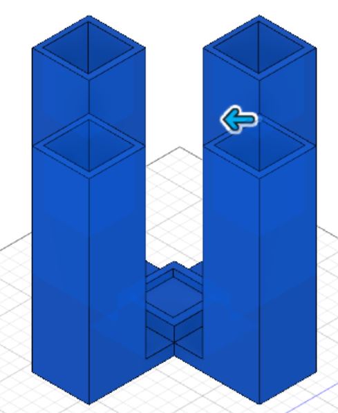
Next, I designed the tower for the servo motors and rubik's cube to mount onto. I searched for images of similar machines online, and used this one as reference. I started by drawing a sketch of the base, then extruding it by varying amounts, and in the 4 main beams of the tower, I created negative extrusion for the servo mounts.
For the motors, I attempted to insert them from the McMaster-Carr components catalogue, but for some reason, I was not able to download it. Therefore, I searched online, and found this model on GrabCAD. I inserted them into the design, then duplicated them and positioned them into their slots.
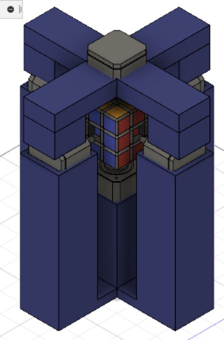
I also designed the dome for the upper servo mount using the bottom half's dimensions, and where the motors were placed. I then inserted it into the current design, along with the rubik's cube. One thing I forgot to do was create a hole for the top motor to mount onto, so I went back and created a negative extrusion into the center by its exact length. The final result looked like this.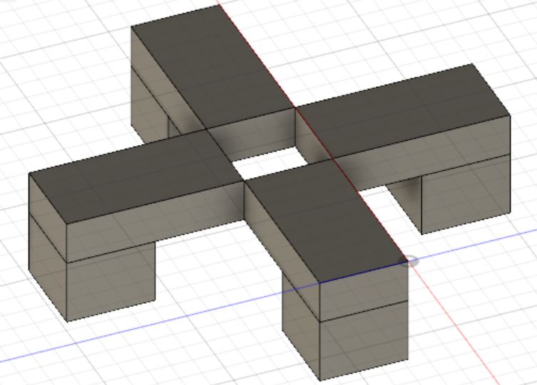
After making adjustments to all the components inserted into the design, I entered Render mode, where I made the tower and dome look like a realistic color if it were 3D-printed. The end result looked like this:
 This is a very basic shape, but it helped me to understand the mechanism and components I will need to think about.
Finally, I decided to try animating my model. Fusion 360 has a basic animation system integrated. It is quite handy when you have complex designs and you need to do an explosion of all the components.
Creating an exploded animation of my prototype was challenging. I could not figure out how the animation was being recorded. Eventually, I realized that every change to the design was recorded individually on the timeline. Fusion 360 offers a feature to automatically explode the drawing, but I decided to manually transform all object. It was time taking, but some components, such as the motor, could be selected and moved together, just like the Mirror tool. An important thing to note is that if one component needs to carry out to transformations, it is important to select the 'split transforms' option in the dialog box. After creating the entire animation, I decided to publish it in the mp4 format. Whilst I was happy with the outcome, I felt that the animation would be better if all the components were reassembled. I found out that clicking on the storyboard reversed all transformations. I then published this as a second mp4, and merged them in a video editing software called Filmora. Finally, I used an online converter to convert it into the .gif format and compress it. The final result looks like this:
 Click here to download the Rubik's Cube Model
 Click here to download the Rubik's Cube Tower Model
Click here to download the Logo 2D Graphics File